
FOXBORO FBM201e Analog Input (0 to 20 mA) Interface Modules
FOXBORO FBM201e Analog Input (0 to 20 mA) Interface Modules
The FBM201e Analog Input Interface Module provides eight dc current input channels.
FEATURES

Key features of the FBM201e module are:
Eight 0 to 20 mA dc channels for input of analog
sensor signals
Each analog input channel is galvanically isolated
from other channels and ground
Compact, rugged design suitable for enclosure in
Class G3 (harsh) environments
Execution of an analog input application program
that provides conversion time and configurable
options for integration time and Rate of Change
Limits
High accuracy achieved by sigma-delta data
conversions for each channel
Termination Assemblies (TAs) for locally or
remotely connecting field wiring to the FBM201e
Termination Assemblies for per channel internally
and/or externally loop powered transmitters.
OVERVIEW
Each FBM201e Analog Input Interface Module
contains eight analog input channels, each channel
accepting a 2-wire, dc input from an analog sensor
such as a 4 to 20 mA transmitter
The modules perform the signal conversion required
to interface the electrical input signals from the field
sensors to the optionally redundant fieldbus.
COMPACT DESIGN
The FBM201e module has a compact design, with a
rugged extruded aluminum exterior for physical
protection of the circuits. Enclosures specially
designed for mounting the FBMs provide various
levels of environmental protection, up to harsh
environments per ISA Standard S71.04.
HIGH ACCURACY
For high accuracy, the module incorporates sigma
delta data conversion on a per-channel basis, which
can provide a new analog input reading every 25 ms,
and a configurable integration period to remove any
process noise and power-line frequency noise.
Each time period, the FBM converts each analog
input to a digital value, averages these values over
the time period, and provides the averaged value to
the controller.
EASY REMOVAL/REPLACEMENT
The module can be removed/replaced without
removing field device termination cabling, power or
communications cabling.
VISUAL INDICATORS
Light-emitting diodes (LEDs) incorporated into the
front of the modules provide visual status indications
of Fieldbus Module (FBM) functions.
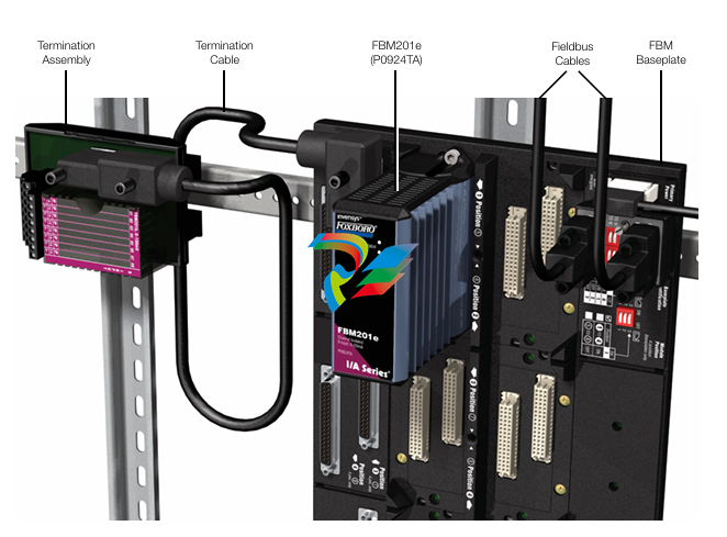
MODULAR BASEPLATE MOUNTING
The module mounts on a modular baseplate (see
Figure 1) which accommodates up to four or eight
FBMs. The modular baseplate is either DIN rail
mounted or rack mounted, and includes signal
connectors for redundant fieldbus, redundant
independent dc power, and termination cables.
FIELDBUS COMMUNICATION
A Fieldbus Communication Module or a Control
Processor interfaces the redundant 2 Mbps module
Fieldbus used by the FBMs. The FBM201e module
accepts communication from either path (A or B) of
the redundant 2 Mbps fieldbus – should one path fail
or be disabled at the system level, the module
continues communication over the active path.
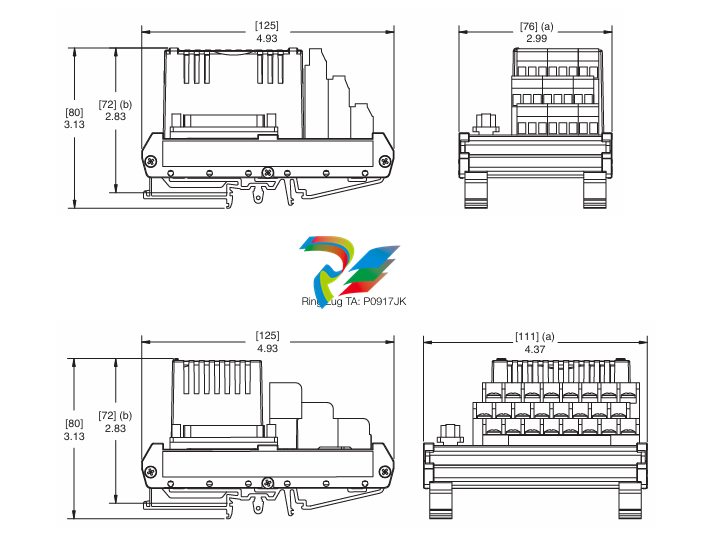
TERMINATION ASSEMBLIES
Field I/O signals connect to the FBM subsystem via
DIN rail mounted TAs (see Figure 1). The TAs used
with the FBM201e module are described in
“TERMINATION ASSEMBLIES AND CABLES” on
page 7
FUNCTIONAL SPECIFICATIONS
Process I/O Communications
Communicates with its associated FCM or FCP via
the redundant 2 Mbps module Fieldbus.
Input Channels
8 isolated and independent channels
Input Range (each channel)
0 to 20 mA dc
Input Channels (8)
ANALOG ACCURACY (INCLUDES LINEARITY)
±0.02% of span
Accuracy temperature coefficient: ±50 ppm/ºC
FIELD DEVICE CABLING DISTANCE
Maximum distance of the field device from the
FBM is a function of compliance voltage @20 mA
(21.4 V dc), wire resistance, and voltage drop at
the field device.
Input Channel Isolation
Each channel is galvanically isolated from all other
channels and earth (ground). The module/TA
withstands, without damage, a potential of 600 V ac
applied for one minute between any channel and
ground, or between a given channel and any other
channel.
WARNING
This does not imply that these channels are
intended for permanent connection to
voltages of these levels. Exceeding the limits
for input voltages, as stated elsewhere in this
specification, violates electrical safety codes
and may expose users to electric shock.
Power Requirements
INPUT VOLTAGE RANGE (REDUNDANT)
INPUT CHANNEL IMPEDANCE
61.5 Ω nominal
INPUT SIGNAL A/D CONVERSION
Each channel performs A/D signal conversion
using an independent Sigma-Delta converter.
INTEGRATION PERIOD
Software configurable.
COMMON MODE REJECTION
>100 db at 50 or 60 Hz
NORMAL MODE REJECTION
>95 db at 50 or 60 Hz
LOOP SUPPLY
24 V dc ±2.5%
OUTPUT IMPEDANCE
68 Ω
LOOP POWER SUPPLY PROTECTION
Each channel is channel-to-channel galvanically
isolated, current limited, and voltage regulated.
All analog inputs are limited by their design to less
than 30 mA. If the current limit circuit shorted out,
the current is limited to about 100mA.
24 V dc +5%, -10%
CONSUMPTION
7 W (maximum)
HEAT DISSIPATION
3 W (maximum)
Calibration Requirements
Calibration of the module and termination assembly is
not required
FUNCTIONAL SPECIFICATIONS (CONTINUED)
Regulatory Compliance
ELECTROMAGNETIC COMPATIBILITY (EMC)
European EMC Directive 89/336/EEC
Meets: EN 50081-2 Emission standard
EN 50082-2 Immunity standard
EN 61326 Annex A (Industrial
Levels)
CISPR 11. Industrial Scientific and Medical
-
 Hirschmann RS20-1600M2T1SDAEHH03.1.02 Rail Switch
 -
 Hirschmann BRS30-24TX Industrial Rail Switch
 -
 Hirschmann RSPM20-4T14T1EV9HHS999.9.99 Managed Ethernet Switch
 -
 Hirschmann BELDEN RS40-0009CCCCSDAPHH09.0.14 / RS400009CCCCSDAPHH09014
 -
Hirschmann RS40 Rail Switch RS40-0009CCCCSDAE
-
 Hirschmann BELDEN RS30-0802T1T1SDAP / RS300802T1T1SDAP Fully Managed Layer 2 Compact Rail Switch
 -
 Hirschmann BELDEN RS20-0800M2M2SDAUHH / RS200800M2M2SDAUHH
 -
 Hirschmann EAGLE30-04022O6TT999SCCY9HSE3F Industrial Firewall Router Switch
 -
 Hirschmann RS20-1600T1T1SDAEHH09.0.14 RS20 Rail Mount Ethernet Switch
 -
 Hirschmann EAGLE0200T1T1TDDY90000HHE05.3.03 Industrial Security Router
 -
Hirschmann - BELDEN MIPP-AD-1L9P
-
 HIRSCHMANN RSPM20-4Z64Z6TV9HHS9 942 106-999 RAIL SAFETY SWITCH
 -
 HIRSCHMANN FIBEROPTIC MODULE FIP P/N: OZDFIPG3T
 -
 HIRSCHMANN RS20-1600M2M2SDAUHH Ethernet rack-mounted switch
 -
 HIRSCHMANN BELDEN RS20-0400T1T1SDAEHH04.0.01 / RS200400T1T1SDAEHH04001
 -
HIRSCHMANN MM2-4FXM3 MICE Media Module
-
HIRSCHMANN RS20-0800M2M2SDAE Industrial Ethernet Rail Switch
-
 Hirschmann RS20-2400T1T1SDAP / RS20-2400T1T1SDAPHH05.0.02
 -
 GE MLJ1005B010H00C MLJ Digital Synchromism Check
 -
 ALSTOM MICROTECH DX21-M2 Digital Excitation Controller
 -
HIRSCHMANN BRS20-1200ZZZZ-STCY99HHSES
-
 HIRSCHMANN MM3-4FXM2 MICE Media Module
 -
Hirschmann RSB20-0800T1T1SAABHH 8Port ENet Rail Switch RSB20
-
 Hirschmann MACH102-8TP Ethernet Switch
 -
 SAACKE DDZ-M marine steam pressure atomizer
 -
 SAACKE SKV-A marine rotary cup atomizer
 -
 SAACKE Seavis HMI05e
 -
 Kollmorgen MMC-SD-2.0-230 Servo Drive 100-240VAC 2KW 10A Output 3PH 100-240VAC
 -
 Kollmorgen Servo drive CR10550
 -
 Kollmorgen AKD-P01207-NACN-0054 Servo Driver
 -
 Kollmorgen S406M-CA-036 Servostar
 -
.png) Kollmorgen AKD-B02407-NAAN-0000 Digital Servo Drive
Kollmorgen AKD-B02407-NAAN-0000 Digital Servo Drive -
 Kollmorgen SERVOSTAR S406AM-CA Digital Servo Drive
 -
 KOLLMORGEN SERVOSTAR 603-AS SERVO AMPLIFIER_SERVOSTAR603AS_S60301
 -
Kollmorgen S700 Servo Controller (S70602-NANANA-NA)
-
 Kollmorgen MPK411 controller
 -
 KOLLMORGEN MMC-SD-1.3-460-D Smart Drive
 -
 KOLLMORGEN AKM21C-CKB2AA-00 / AKM21CCKB2AA00 Servomotor
 -
 BECKHOFF AX5106-0000-0200 | Digital Compact Servo Drives 1-channel
 -
 BECKHOFF C3620-0000 INDUSTRIAL COMPUTER (MOTORSHELVES)
 -
 Beckhoff EK1960-0000 TwinSAFE Compact Controller
 -
 Beckhoff C6930-0050 Control Cabinet Industrial PC
 -
 Beckhoff CP7711-0001-0030 Industrial Computer Detection
 -
 Beckhoff CX1001-0111 Embedded PC CPU Module
 -
 Beckhoff C6017-0020 | Ultra-compact Industrial PC
 -
 Beckhoff EK1322 | 2-port EtherCAT P junction with feed-in
 -
 Beckhoff CP2219-0010 Panel
 -
 BECKHOFF C6015-0020 ULTRA COMPACT INDUSTRIAL PC
 -
 BECKHOFF CX2030-0120/Standard CPU Module Embedded PC Windows PLC controller
 -
 Beckhoff CP7721-1090-0020 Panel PC
 -
 Beckhoff PC CPU Module CX5130-0175
 -
 Beckhoff C6920-0050 Control Cabinet
 -
 Beckhoff EL6631 EtherCAT 2-Port Communication Interface, Profinet RT Controller
 -
 Beckhoff CP6202-0001-0060 touch screen panel PC
 -
 Beckhoff CP3916-1002-0000 Multi-Touch Control Panel
 -
 Beckhoff EP1809-0021 | EtherCAT Box, 16-channel digital input, 24 V DC, 3 ms, M8Preferred type
 -
 Beckhoff CX8190 PLC Embedded Industrial PC Ethernet Controller
 -
 Beckhoff CX2100-0914 Power Supply for External
 -
 Beckhoff Automation CP6906-0001-0000 HMI
 -
 Beckhoff EP7342-0002 Module
 -
 Beckhoff CX1020-0112 / CX1100-0910 / CX1020-N010 / CX1100-0003 Windows CPU
 -
 Beckhoff EP7211-0034 EtherCAT Box 1 Channel Motion Interface
 -
 Beckhoff C6240-0030 Control cabinet Industrial PC
 -
 beckhoff motherboard CB1052-0004 CB1052-0004
 -
 Beckhoff AX2006-AS Servo Drive / Variable Frequency Drive
 -
BECKHOFF CP6207-0001-0020 NSMP
-
 Beckhoff C6930-1142-0060 Industrial Computer
 -
 Beckhoff FC7501-0000 interface card
 -
 Beckhoff CX5140-0175 Embedded PC PLC CPU CX5140 Industrial Controller
 -
 Beckhoff CP7802-1100-0010: High-End IP65 Control Panel with DVI/USB Extended Interface
 -
BECKHOFF CP3716-1058-0010 CONTROL PANEL
-
 Beckhoff AX8108-0000 Single-Axis Module
 -
 Beckhoff CU8851-0000 | USB extension, USB Extended 2.0 receiver box
 -
Beckhoff C6017-0030 | Ultra-compact Industrial PC
-
 Beckhoff CX1001-0120/CX10010120.cx1000-n001.cx1000-n000 System Overview
 -
 Beckhoff CPU Module CX5140-0155/4GB CPU Module
 -
 Beckhoff CP6533-0001-005: Built-in Panel PC with High-Definition Multi-Touch Control
 -
 Beckhoff EL5042 | EtherCAT Terminal, 2-channel encoder interface, BiSS® C
 -
 Beckhoff C6920-1080-0040: Premium Control Cabinet Industrial PC
 -
 Beckhoff C6920-0060 | Control cabinet Industrial PC
 -
 Beckhoff Embedded-PC CX5010-1121
 -
 Beckhoff CB3050-0010 Mainboard Motherboard
 -
 Beckhoff PLC module CX1020-0000 Basic CPU module (service phase)
 -
 Beckhoff CP7812-1056-0010 15" Multitouch Display Control Panel
 -
 Beckhoff CX5120-0115 /2GB Controller Module
 -
 Beckhoff CP7201-1000-0000 Industrial Panel PC
 -
 Beckhoff Servo Motor AM8061-0JH1-0000
 -
 BECKHOFF CP6503-0001-0050 Built-in Panel PC
 -
Beckhoff CP3919-0010 Display G190ETN01.2 19" PCT V04. Multi-touch Control Panel
-
 Beckhoff CX5110-0112-9020/000368201 Embedded PC Intel Atom Processor
 -
 Beckhoff AX8206-0000 Dual-Axis Module
 -
Beckhoff Nail Operating Terminal CP7032-1031-0010
-
Beckhoff AM8042-0EH1-0000 Servomotor 4.10 Nm (M0), F4 (87 mm)
-
 Beckhoff EK9300 Beckhoff CPU Module
 -
Beckhoff CP3224-0020 Multitouch-Panel-PC
-
 Beckhoff CP2712-0000 12.1" 24VDC Touch Screen WMD0
 -
 BECKHOFF CX5240-0195 / 0000289234 Embedded PC 40 GB CFast Card
 -
 Beckhoff CP6932-1000-0000 Control Panel
 -
 BECKHOFF CX5120-0121 PLC Module
 -
 Beckhoff EL3218 | EtherCAT Terminal, 8-channel analog input
 -
Beckhoff C6640-0050 | Control cabinet Industrial PC
-
 Beckhoff Cx5130-0120/4GB Embedded-PC
 -
 BECKHOFF CX2030-0122 PLC PROCESSOR
 -
 BECKHOFF CX5020-0122 Controller Module
 -
 Beckhoff CP3915-0000 Multitouch Panel
 -
 BECKHOFF EL3014 | EtherCAT Terminal
 -
 BECKHOFF Industrial Computer c6920-1057-0030
 -
 Beckhoff CX5130-0141/4GB CX5130-0141 Embedded PC
 -
 Beckhoff C6240-1052-0040 4-086-06-3073 Industrial Computer
 -
 Beckhoff CX5140-0135 /4GB High-Performance Embedded Industrial PC
 -
 Beckhoff C6515-1001-0000 Industrial PC
 -
 Beckhoff AX5103-0000-0200 - Digital Compact Servo Drives
 -
 Beckhoff CX2030-0130-1003/4GB Basic CPU module
 -
 Beckhoff AX8620-0000 Power Supply Module
 -
 Beckhoff CX9020-0111 module with
 -
 Beckhoff EL7332 PLC Module
 -
 BECKHOFF CP7709-0001-0020 HMI
 -
 Beckhoff CX5120-0155/2GB Embedded PC
 -
 BECKHOFF CP7037-1037-0010 OPERATOR INTERFACE TOUCHSCREEN
 -
 Beckhoff EK9000 | ModbusTCP/UDP Bus Coupler
 -
 Beckhoff Touch Panel Screen CP6020 -0000-0000
 -
 Beckhoff CX2020-0121 Module FAST Shipping
 -
 Beckhoff CX2030-0125 Basic CPU Module
 -
 Beckhoff CP3918-0000 Multi-Touch 18.5" Control Panel
 -
 Automotion LC4A00010 DC BL Motor Control, ATS, Sub Assy, SCP, 115VAC,
 -
 500T-115VAC - VAS ENGINEERING - DORIC 500 SERIES DIGITAL TEMP INDICATOR
 -
 Honeywell X-DCS2000/EN Digital Integrated System Manager 50/60Hz 100-240V #4
 -
 Kollmorgen S60600 Servostar600 606-Fan 4 kVA, 6 A, 3 X 230 - 480 V


