
NIOPERATING INSTRUCTIONS AND SPECIFICATIONS NI 9505
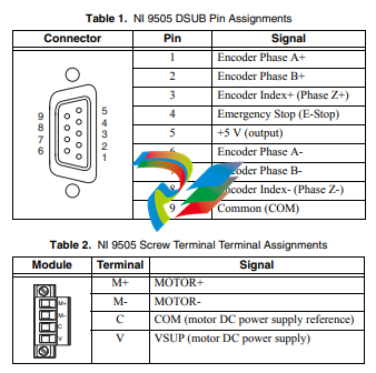
The NI 9505 also has a screw terminal connector that provides
connections to a motor DC power supply and a DC brushed servo
motor. Connect the positive lead of the power supply to terminal 4,
VSUP, and the negative lead to terminal 3, COM. Refer to Table 2
for the terminal assignments.
Note You must use 2-wire ferrules to create a secure
connection when connecting more than one wire to a
single terminal on the NI 9505 screw terminal.
Caution Do not turn on or plug in the motor DC power
supply until the screw terminal connector is fully inserted.
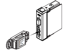
Optional Screw Terminal Accessory
Use the NI 9931 Screw Terminal Accessory instead of the
detachable screw terminal connector to increase the output power
of the module at temperatures below 70 ºC. The NI 9931 is
available from ni.com (NI part number 780571-01) or by calling
your National Instruments sales representative. Refer to the
Specifications section for more information. Refer to Figure 5 for
an illustration.
Figure 5. NI 9505 Module with Optional Screw Terminal Accessory
Wiring for High Vibration Applications
National Instruments recommends using ferrules to terminate
wires to the detachable screw terminal connector or the NI 9931
Screw Terminal Accessory when you use the NI 9505 in high
vibration applications. Refer to Figure 6 for an illustration.
Figure 6. 4-Terminal Screw Terminal Connector or
Accessory with a Ferrule
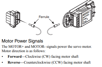
Motor Power Signals
The MOTOR+ and MOTOR- signals power the servo motor.
Motor direction is as follows:
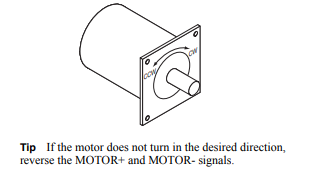
• Forward—Clockwise (CW) facing motor shaft
• Reverse—Counterclockwise (CCW) facing motor shaf
Encoder Signals
The encoder signals consist of a Phase A, Phase B, and Index
(Phase Z) input. The NI 9505 supports differential and
single-ended inputs for Phase A, Phase B, and Index (Phase Z)
signals. Figures 8 and 9 show simplified schematic diagrams of the
encoder input circuit connected to differential and single-ended
inputs. You can also accommodate open-collector output encoders
by using a 1 kΩ pull-up resistor on each line to +5 VDC. Refer to
the Specifications section for more information about the encoder
inputs.
The encoder signals are raw digital input signals. These signals are
used in the LabVIEW FPGA Module for position and/or velocity
feedback. Figures 8 and 9 illustrate the use of the encoder signals
in a position and velocity loop in the LabVIEW FPGA Module.
Refer to the examples installed at labviewexamples
CompactRIOModule SpecificNI 9505 for examples of using
the encoder signals. Refer to the NI 9505 Reference Help book
in the LabVIEW Help, available by selecting Help»Search the
LabVIEW Help, for more information.
If the encoder cable length is greater than 3.05 m (10 ft), use
encoders with differential line driver outputs for your applications.
Power for a +5 V encoder—generated by a power supply inside the
NI 9505—is available on pin 5 of the DSUB connector.
Note The internal power supply is powered through the
Vsup pin.
Closed-loop servo applications require consistent directional
polarity between the motor and encoder for correct operation.
One industry-standard directional polarity is as follows:
• Positive = forward = clockwise (CW) facing motor shaft
• Negative = reverse = counterclockwise (CCW) facing motor
shaft
Refer to Figure 7 for a depiction of clockwise and
counterclockwise rotation. If encoder counting does not behave as
expected, change the encoder polarity in the FPGA or swap the
Phase A and Phase B connections.
When connecting the encoder wiring to the NI 9505, use shielded
wire of at least 24 AWG. You must use cables with twisted pairs
and an overall shield for improved noise immunity. Refer to
Figure 4 for a connection example.
Note Using an unshielded cable may produce noise,
which can corrupt the encoder signals and cause lost
counts, reduced accuracy, or other erroneous encoder and
drive operation.
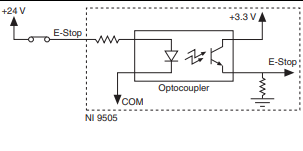
Emergency Stop Signal
The E-Stop signal is an input to the drive from an emergency stop
switch. Figure 10 shows a simplified schematic of the emergency
stop input circuit. When the emergency stop switch is closed,
current flows through the circuit, and the drive is enabled. When
an external event activates the emergency stop switch, the switch
opens and current stops flowing, disabling the drive. The E-Stop
functionality is disabled by default. Refer to the NI 9505 Reference
Help book in the LabVIEW Help, available by selecting Help»
Search the LabVIEW Help, for information about how to enable
this signal using the Enable E-Stop Property.
Figure 10. Emergency Stop Input Circuit
Cable Requirements for EMC Compliance
Use the following guidelines when selecting cables for the
NI 9505:
• Use shielded cables with a low impedance connection to
chassis ground to minimize noise and signal crosstalk.
• Tie the VSUP cable shield to chassis ground at the module side
-
 AMAT 0100-00046 AC Current Sense PWB
 -
 AMAT A0414720 Precision Advanced System Controller
 -
 AMAT 0010-00017 Precision Semiconductor Process Interface
 -
 AMAT 01-82889-00 High-Performance Semiconductor Component
 -
 ABB Sample Gas Cooler SCC-C 23070-0-10232110
 -
 IBA ibaRackline-PCHD Efficient process analysis with ibaHD-Server
 -
IBA ibaRackline-PC CAM Frame-accurate video information with ibaCapture
-
IBA ibaRackline-PC Highly available and reliable
-
 IBA Optical Signal Multiplier ibaBM-FOX-i-3o-D
 -
 IBA Optical Data Distribution System ibaBM-DIS-i-8o
 -
IBA Optical Data Concentrator ibaBM-COL-8i-o
-
 IBA ibaNet750-BM-D Acquisition via FO
 -
 IBA ibaW-750 Acquisition via Ethernet
 -
 IBA ibaPADU-8AI-I Compact Measurement Modules
 -
 IBA ibaPADU-D-8AI-I Compact Measurement Modules
 -
 IBA ibaPADU-8AI-U Compact Measurement Modules
 -
 IBA ibaPADU-D-8AI-U Compact Measurement Modules
 -
 IBA ibaPADU-4-AI-U Compact Measurement Modules
 -
 IBA ibaPADU-C-8AI Self-Supplied Data Logger
 -
 IBA ibaBM-ENetIP Bus monitor for EtherNet/IP
 -
 IBA ibaBM-eCAT Bus monitor for EtherCAT
 -
 IBA ibaBM-DP Bus monitor for PROFIBUS
 -
 IBA ibaBM-PN: Bus monitor for PROFINET IO
 -
 IBA ibaMS3xAI-1A Precision AC Current Measurement Module
 -
 IBA ibaDAQ Intelligent Central Unit
 -
 IBA ibaPQU-S Power Quality Monitoring System
 -
 IBA ibaCMU-S Condition Monitoring Unit (CMU)
 -
 IBA ibaPADU-S-IT-2x16 Modular data acquisition and control system
 -
IBA ibaPADU-S-CM Modular data acquisition system
-
 IBA ibaM-4AI-IEPE Input module
 -
IBA ibaM-4AI-UI Input module
-
IBA ibaM-4AI-150V-AC Input module
-
 IBA ibaM-4AI-600V-AC Input module
 -
 IBA ibaLink-SM-256V: High-Density PLC Data Interface
 -
 IBA ibaLink-SM-64V High-Performance S5/S7 Interface
 -
IBA ibaLink-SM-128V-i-2o Synchronous Fiber Optic (ibaNet)
-
 IBA ibaLink-SM-128V communication module
 -
IBA ibaM-4AI-5A-150A-AC Input module
-
 IBA ibaM-FO-2IO Interface module
 -
 IBA ibaM-COM Communication module
 -
 IBA ibaM-DAQ Intelligent Processor Module
 -
 B&R ECE161-0 MULTI digital input module
 -
 B&R ECCP70-01 MULTI CPU type B 42 KByte SRAM
 -
 B&R ECCP60-01 MULTI CPU type B 42 KByte SRAM
 -
 B&R DI426 digital input module
 -
 B&R 2DS100.60-1 electronic drum sequencer Absolut encoder
 -
 B&R 2CP100.60-1 CPU MODULE
 -
 B&R 2BM100.9 High-performance I/O module
 -
 AMAT 0190-14928 SCR Power Controller (PVD Reverse Zone)
 -
 AMAT 0500-01065 300mm Loadlock Interface Interlock Board
 -
 AMAT 2000-21123 Advanced Vacuum Seal Assembly
 -
 AMAT 0660-00090 High-Performance Industrial Power Filter
 -
 AMAT 0240-34077 Centura Endpoint Controller Kit
 -
 AMAT 0195-10215 High-Precision Pedestal Assembly
 -
 AMAT 0190-76050 VGA Video Controller VME Module
 -
 AMAT 0190-75084 High-Performance Communication & Logic Controller
 -
 AMAT 0190-60287 Precision VME/cPCI Interface Control Module
 -
 AMAT 0190-53752 DI Water I/O Controller PCB
 -
 AMAT 0190-37993 DeviceNet Scanner Pro (3U CompactPCI)
 -
 AMAT 0190-37833 MKS CDN500R-5 EPI 300mm Interface Module
 -
AMAT 0190-37771 MKS CDN500R Interlock Control Module
-
 AMAT 0190-37616 High-Precision Analog Input/Output Interface
 -
 AMAT 0190-36787B ISAC CP I/O Block 2 (Top) - Revision B
 -
 AMAT 0190-36787 ISAC CP I/O Block 2 (Top)
 -
AMAT 0190-36511 DIP294 DeviceNet I/O Control Block
-
 AMAT 0190-35764 & 0190-35765: Precision Control Interface Duo
 -
 AMAT 0190-35763 High-Performance Integrated Power Module
 -
 Applied Materials (AMAT) 0190-34512 4-Channel DeviceNet Scanner Interface
 -
 Applied Materials (AMAT) 0190-34282 High-Stability Process Control Module
 -
Applied Materials (AMAT) 0190-27707 High-Precision DeviceNet I/O Controller
-
 Applied Materials (AMAT) 0190-27072 High-Performance Semiconductor Interface
 -
 AMAT 0190-24007 CPCI-3720CF Single Board Computer
 -
 AMAT 0190-23905 Spellman ESC High Voltage Power Supply
 -
 AMAT 0190-22967 High-Density Analog I/O Control Board
 -
 AMAT 0190-22543 High-Precision Analog Input/Output Module
 -
 AMAT 0190-17964 Etch DPS Interlock Module
 -
 AMAT 0190-17894 Interlock Module Conductor HART
 -
 AMAT 0190-17081 2U CompactPCI System Host Processor
 -
 AMAT 0190-16926 and 0190-16928 Based on Compact PCI
 -
AMAT 0190-15915 Intelligent I/O Control Module
-
 AMAT 0190-15840 4-Port UPA DeviceNet Interface Module
 -
 AMAT 0190-15384 Advanced Digital Signal Interface Module
 -
 AMAT 0190-14027 Wafer Flat Finder PCB
 -
 AMAT 0190-12695 SBS CL7 3U CompactPCI Single Board Computer
 -
 AMAT 0190-11817 CP3-SER16-TTL 16-Port Serial Interface Card
 -
 AMAT 0190-11524 CDN500-25 Interlock Module
 -
 AMAT 0190-07450 CompactPCI 48-Channel Digital I/O Interface Board
 -
 AMAT 0190-05990-001 Maglev Rotation System Controller (300mm)
 -
 AMAT 0190-05647 LK3710 Serial Module Transition Card
 -
 AMAT 0190-04457 High-Performance Integrated Circuit Control Module
 -
 Applied Materials (AMAT) 0190-04098 | 5.X Factory Interface I/O Distribution Board
 -
 Applied Materials (AMAT) 0190-03705 | MF Producer SE/E Interlock Module
 -
 Applied Materials (AMAT) 0190-02748 | Flex Scanner Transition Module
 -
 Applied Materials (AMAT) 0190-02362 | Mainframe Interlock 1 Relay Module
 -
 Applied Materials (AMAT) 0190-01227 | Intelligent Motor Control OMS Board
 -
 Applied Materials (AMAT) 0190-00318 | VME 486 Video Controller
 -
 Applied Materials (AMAT) 0130-14007 | Advanced RF Signal Assembly
 -
 Applied Materials (AMAT) 0130-14005 | RF Cable/Interface Assembly
 -
 Applied Materials (AMAT) 0130-01218 | High-Efficiency RF Interface Controller
 -
 Applied Materials (AMAT) 0110-77040 | Head Pneumatic Controller
 -
 Applied Materials (AMAT) 0110-00077 | Precision Control Module
 -
 AMAT 0101-57015 high-performance Next-Generation Deflection Amplifier Board
 -
 AMAT 0100-77040 critical Head Pneumatic Controller Board
 -
 AMAT 0100-76291 Data Buffer / Memory Expansion Interface
 -
 AMAT 0100-76290 Advanced I/O Interface Board
 -
 AMAT 0100-76269 Control Board / Interface Module
 -
 AMAT 0100-71462-01 high-performance Process Controller PCB
 -
 AMAT 0100-71171 Chamber Interlock Control PCB
 -
 AMAT 0100-71154 Semiconductor Circuit Board / Electronic Group Card
 -
 AMAT 0100-70034 PCB Assembly (PCBA) for Endpoint VGA I/O Interconnect.
 -
 AMAT 0100-38032 ESC (Electrostatic Chuck) Controller PCB
 -
 AMAT 0100-36035 DPS Source Match / Seriplex I/O Distribution PCB
 -
 AMAT 0100-35231 Seriplex I/O Distribution Module
 -
 AMAT 0100-35217 TC Amp Interlock PCB Module
 -
 AMAT 0100-35065 High-Precision Serial Isolator PCB
 -
 AMAT 0100-35054 Advanced Chamber Interface Module
 -
 AMAT 0100-20453 DeviceNet Digital I/O Interface Board
 -
 AMAT 0100-20100 High-Performance Semiconductor Component
 -
 AMAT 0100-20068 Precision CCD Image Control Board
 -
 AMAT 0100-20064 Advanced Semiconductor Control Module
 -
Applied Materials (AMAT) 0100-20018 Advanced Communication Interface Module
-
 Applied Materials (AMAT) 0100-20016 High-Performance Interface and Control Module
 -
 Applied Materials (AMAT) 0100-20003 Digital I/O (DI/DO) Interface Board
 -
 Applied Materials (AMAT) 0100-20001 System Electronics Interface (SEI) / PCB Assembly
 -
 Applied Materials (AMAT) 0100-11030 Chamber Hardware / Gas Distribution Component
 -
 Applied Materials (AMAT) 0100-11022 Semiconductor Board Card
 -
 Applied Materials (AMAT) 0100-11018 Advanced Interface Control Module
 -
 Applied Materials (AMAT) 0100-11001 Precision Analog Output Board


