
WATLOWEZ-ZONE® PMUser’s GuidePID Controller Models
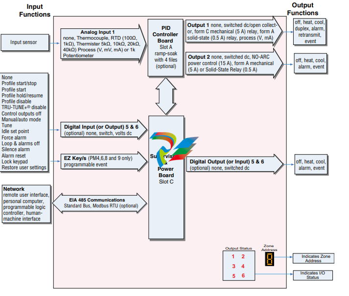
It is useful to think of the controller in three parts: inputs; procedures; and outputs. Information flows from an input to a procedure to an output when the controller is properly
configured. A single PM controller can carry out several procedures at the same time, for
instance closed-loop control, monitoring for several different alarm situations and operating
switched devices, such as lights and motors. Each process needs to be thought out carefully
and the controller’s inputs, procedures and outputs set up properly.
Inputs
The inputs provide the information that any given programmed procedure can act upon. In a
simple form, this information may come from an operator pushing a button or from a sensor
monitoring the temperature of a part being heated or cooled.
Each analog input typically uses a thermocouple or RTD to read the process temperature. It
can also read volts, current or resistance, allowing it to use various devices to read a wide
array of values.
A PM with digital input/output (DIO) hardware includes two sets of terminals where each of
which can be used as either an input or an output. Each pair of terminals must be configured
to function as either an input or output with the direction parameter in the Digital Input/
Output Menu (Setup Page). Each digital input reads whether a device is active or inactive.
The Function or EZ Key/s (PM4/6/8/9 only) on the front panel of the PM also operates as a
digital input by toggling the function assigned to it in the Digital Input Function parameter in
the Function Key Menu (Setup Page).
Internal Functions
The controller will use input signals to calculate a value and then perform an operation. A
sample of some functions may be as simple as:
• Compare an input value to the set point and calculate the optimal power for a heater
• Detect a failure of the primary sensing device and trip a contactor to remove power from
the heating element
• Reading a digital input to set a state to true or false
• Evaluate an incoming temperature to determine an alarm state (on or off)
To set up a function, it’s important to define the source, or instance, to use. For example, if
the control is equipped with DIO they can be configured to respond to an alarm. If configured
as such, the digital output must be tied to the desired alarm instance (1 to 4). Using this as
an example, the Function for the digital output would be defined as an Alarm where the Instance would be selected as 1, 2, 3, or 4 corresponding to the alarm instance that will drive
the output.
Keep in mind that a function is a user-programmed internal process that does not execute
any action outside of the controller. To have any effect outside of the controller, an output
must be configured to respond to a function..
Outputs
Outputs can perform various functions or actions in response to information provided by a
function such as, removal of the control voltage to a contactor; operating a heater, turning a
light on or off, unlocking a door, etc...
Assign a Function to any available output on the Setup Page within the Output Menu or Digital Input/Output Menu. Then select which instance of that function will drive the selected
output. For example, you might assign an output to respond to alarm 4 (instance 4).
You can assign more than one output to respond to a single instance of a function. For example, alarm 2 could be used to trigger a light connected to output 1 and a siren connected
to digital output 5.
Input Events and Output Events
Input and output events are internal states that are used exclusively by profiles. The source
of an event input can come from a real-world digital input or an output from another function. Likewise, event outputs may control a physical output such as an output function block
or be used as an input to another function.
What is a Profile
A profile is a set of instructions consisting of a sequence of steps. When a profile runs, the
controller automatically executes its steps in sequence. The step type determines what action the controller performs. Steps can change temperatures and other process values gradually over time, maintain the temperatures and process values for specific periods, or repeat
a sequence of steps numerous times. At each step the profile can activate or deactivate
outputs that control other equipment. Also a step can have the controller wait for specific
conditions before proceeding such as, waiting for a switch closure and/or a specific process
value to be detected by a sensor.
EZ-ZONE® PM PID Model System Diagram
Universal Sensor Input, Configuration Communications,
Red/Green 7-Segment Display
Chapter 2: Install and Wire
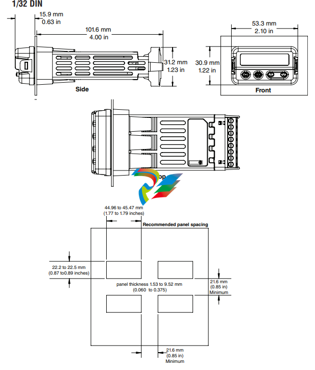
Installation
1. Make the panel cutout using the mounting template dimensions in this chapter. Insert the
case assembly into the panel cutout.
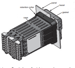
2. While pressing the case assembly firmly
against the panel, slide the mounting collar
over the back of the controller.
Note:
If the installation does not require a NEMA 4X
-
 HIRSCHMANN MSM20-M2M2M2M2SY9HH9E Ethernet media modul
 -
 HIRSCHMANN SPIDER-PL-20-05T1999999TWVHHHH Industrial Ethernet Rail Switch
 -
 Hirschmann SPIDER-PL-20-07T1M2M299TWVHHHH Industrial ETHERNET Rail Switch
 -
.png) Hirschmann (Belden) RS20-1600M2M2SDAEHC09.1.00 DIN-rail managed industrial Fast Ethernet switch
Hirschmann (Belden) RS20-1600M2M2SDAEHC09.1.00 DIN-rail managed industrial Fast Ethernet switch -
 Hirschmann (Belden) RS30-1602O6O6TDAPHC09.1.00 DIN-rail managed industrial Ethernet switch
 -
 Hirschmann (Belden) RS30-2402O6T1SDAPHH09.0.13 DIN-rail industrial Ethernet switch
 -
Hirschmann (Belden) SPIDER-PL-20-04T1S29999TY9HHHH Ethernet DIN-rail switch
-
 HIRSCHMANN RS20-1600T1T1SDAUHX Switch
 -
 HIRSCHMANN BRS42-0012OOOO-SPCZ99HHSES industrial switch
 -
 Hirschmann RS20-0800S2S2TDHPHH09.0.14 Fast Ethernet DIN rail switch.
 -
 HIRSCHMANN MM20-Z6Z6M2M2SAHH Hybrid Fast Ethernet Media Module
 -
 HIRSCHMANN MM20-Z6Z6T1T1SAHH hot-swappable hybrid Fast Ethernet Media Module
 -
 HIRSCHMANN MM20-P9P9T1T1SAHH Hybrid Fast Ethernet Media Module
 -
 HIRSCHMANN MM20-M4T1T1T1SAHH Hybrid Fast Ethernet Media Module
 -
 HIRSCHMANN MM20-M4M4T1T1SAHH Hybrid Fast Ethernet Media Module
 -
 HIRSCHMANN MM20-M2M2M2M2SZHH Ethernet media module
 -
HIRSCHMANN MM20-M2M2M2M2SAHH Ethernet media module
-
 HIRSCHMANN MM20-T1T1T1T1EBH 4-port Fast Ethernet Copper Cable Media Module
 -
HIRSCHMANN MM20-T1T1T1T1SAHH 4-port Fast Ethernet Copper Cable Media Module
-
HIRSCHMANN MM20-T1T1T1T1SAHH 4-port Fast Ethernet Copper Cable Media Module
-
 HIRSCHMANN MM20-Z6Z6EBH Hot-swappable fast Ethernet media module
 -
 HIRSCHMANN MM20-Z6Z6SAHH Ethernet media module
 -
HIRSCHMANN MM20-Z6Z6Z6Z6EBH Industrial Media Module
-
 MSM40-T1T1T1TZ9HH9E99.9.99 HIRSCHMANN Switch
 -
 HIRSCHMANN MS20-0800SAAEHC / MS20-0800SAAEHC0 8-port modular Layer 2 management Ethernet switch
 -
 Hirschmann RSPM20-4T14T1SZ9HHS9 Switch RSPM20-4T14T1SZ9HHS9
 -
 HIRSCHMANN RS20-1600M2M2SDAEHH09.1. RS20/30/40 Managed Switch configurator
 -
HIRSCHMANN RS20-1600M2M2SDAEHX09.0.00 Ethernet switch
-
 HIRSCHMANN BELDEN SPIDER-PL-20-07T1M2M299TY9HHHH / SPIDERPL2007T1M2M299TY9HHHH
 -
HIRSCHMANN MM3-1FXS2/3TX1 Switching Board Module
-
 HIRSCHMANN RSPE30-24044O7T99-ECCP999HHSE2A08.1.00 Industrial-grade fanless management-type Ethernet switch
 -
 HIRSCHMANN RS30-1602OOZZSDAEHC09.1.00 DIN-rail-mounted managed Layer 2 Ethernet switch
 -
 HIRSCHMANN MACH104-20TX-F Managed 24-port Full Gigabit 19" Switch
 -
 HIRSCHMANN Switch RS20-0800M4M4SDAE
 -
Hirschmann RS30-1602O6O6SDAEHH09.1. Management-type Ethernet switch
-
 Hirschmann RS30-1602OOZZSDAEHC09.0.10 Open rack-style Ethernet switch
 -
 HIRSCHMANN RSPE30-24044O7T99-SCCV999HHSI2SXX.X.XX High-Availability Seamless Redundancy
 -
HIRSCHMANN RSPE30-24044O7T99-SCCZ999HHSE2A DIN-rail Ethernet switch
-
HIRSCHMANN MM2-4TX1-EEC switch
-
HIRSCHMANN MSM40-T1T1T1T1TZ9HH9E99.9.99 Module
-
 HIRSCHMANN RS20 Rail Switch RS20-0400S4T1SDAEHC07.1.01
 -
 HIRSCHMANN M4-FAST8-SFP Fast Ethernet media module
 -
 HIRSCHMANN RS20-0400M2T1SDAP Managed Fast-Ethernet-Switch
 -
 HIRSCHMANN BELDEN SPIDER II 8TX/1FX EEC Industrial Ethernet Rail Switch
 -
HIRSCHMANN MM3-2FXS2/2TX1
-
 HIRSCHMANN RS2-4TX/1FX EEC Industrial Ethernet Rail Switch
 -
 RS30-0802O6O6SDAEHC09.0.10 HIRSCHMANN Switch
 -
 HIRSCHMANN m4-8TP-RJ45 Ethernet Media Module
 -
 HIRSCHMANN MSP30-24040SCZ9URHHE3A switch
 -
 Hirschmann rack MS30-1602SAAPHC
 -
 HIRSCHMANN RS2-FX/FX Industrial Switch Module
 -
Rs1txfx - Hirschmann - Rs1-Tx/Fx Rail Switch
-
RS20-0800S2S2SDAEHC09.1.00 HIRSCHMANN Commutator
-
 Hirschmann EAGLE20 TX/TX Industrial Security Router
 -
 Hirschmann SPIDER-SL-20-04T1S29999SY9HHHH Industrial Switch
 -
 HIRSCHMANN MAR1040-4C4C4C4C9999SMMHRHHXX.X. Gigabit Ethernet Switch configurator
 -
 Hirschmann MAR1040 Industrial Switch
 -
 HIRSCHMANN BELDEN RS30-1602O6O6SDAE
 -
Hirschmann RS20-1600M2M2SDAUHC Ethernet DIN rail switch
-
 HIRSCHMANN OCTOPUS 24M industrial switch
 -
 HIRSCHMANN RS20-1600T1T1SDAE Management-type Ethernet switch
 -
 HIRSCHMANN RS20-1600T1T1SDAUHH industrial switch
 -
HIRSCHMANN RS20-0800M2M2SDAPHC09.0.04 switch
-
 Hirschmann MR 8-03 24V DC Industrial Modular Bridge/Router
 -
 HIRSCHMANN RS20-0400M2T1SDAPHC08.0.01 Managed Switch
 -
 MACH1130 Hirschmann Industrial Switch
 -
 HIRSCHMANN 943824-002 SPIDER 5TX Industrial Ethernet Switch
 -
 HIRSCHMANN RS30-0802O6O6SDAEHC09.1.00 Managed Industrial Switch
 -
 HIRSCHMANN RS20-0400M2M2TDAEHC04.0.01 Industrial Switch
 -
 HIRSCHMANN BRS20-0600Z6Z6-STCZ99HHSES Industrial Switch
 -
 HIRSCHMANN MACH104-20TX-FR-L3P Industrial Ethernet Switch
 -
 HIRSCHMANN RS40-0009CCCCEDBPHH06.0.01 Industrial Switch
 -
 HIRSCHMANN RS2-3TX/2FX EEC Industrial Ethernet Switch
 -
 Hirschmann MACH 1020/1030 Fast/Gigabit Rack Mount Switches
 -
HIRSCHMANN RS20-0800M2M2SDAPHC09.0.14 Industrial Switch
-
 HIRSCHMANN RS20-1600T1T1SDAEHC09.0.04 Industrial Switch
 -
 HIRSCHMANN RSB20-0800T1T1EAABHH Industrial Switch
 -
 HIRSCHMANN MACH4002-48+4G-L3E Industrial Backbone Switch
 -
 HIRSCHMANN RS20-0400S2T1SDAE Industrial Managed Switch
 -
HIRSCHMANN RS20-0800S2T1SDAUHC Industrial Switch
-
 HIRSCHMANN RS20-2400S4S4SDAEHC09.0.14 industrial switch
 -
 HIRSCHMANN OS20-001200T5T5T5- TBBZ999HHNE3S 08.1.00 industrial switch
 -
HIRSCHMANN OS20-001200T5T5T5- TBBZ999HHNE3S 08.1.00 industrial switch
-
 HIRSCHMANN RS40-0009CCCCSDAEHH09.0.14 switch
 -
 Hirschmann RS20-1600T1T1SDAUHC Management-type Ethernet Switch
 -
 Hirschmann M1-8SFP Switche
 -
Hirschmann Industrial Ethernet Ruggedized Switch MACH1000 Family
-
 Basler Electric, Solid State Protective Relay, BE1-60
 -
BASLER ELECTRIC SR4A-2B15B3A Static Voltage Regulator
-
.png) BASLER ELECTRIC EXCITER DIODE MONITOR EDM-200
BASLER ELECTRIC EXCITER DIODE MONITOR EDM-200 -
.png) BASLER ELECTRIC DECS125-15-B2C5 DIGITAL EXCITATION CONTROL SYSTEM V 2.0.9
BASLER ELECTRIC DECS125-15-B2C5 DIGITAL EXCITATION CONTROL SYSTEM V 2.0.9 -
 BASLER ELECTRIC BE1-851 OVERCURRENT PROTECTION RELAY MECHANISM
 -
 Basler Electric BE1-51A / BE151A
 -
 Basler Electric BE1-40Q Loss of Excitation Relay
 -
 Basler Electric BE1-87G Variable Percentage Differential Relay
 -
 Basler Electric BE1-11 Protection System I5A3M2P2N0EA00
 -
 BASLER ELECTRIC DECS-200-1C Digital Excitation Control System
 -
 Basler Electric / Kohler BE1-11g Generator Protection Relay G5A3M2J2N0E000
 -
BASLER ELECTRIC DECS125-15 DIGITAL EXCITATION CONTROL SYSTEM
-
 BASLER ELECTRIC BE1-951 OverCurrent Protecton System
 -
Basler Electric DECS-200-1L Digital Excitation Control System
-
 Basler Electric DGC-2020HD-5NS1DNSBA Digital Genset Controller -
 -
 BASLER ELECTRIC BE1-81T1EE1WA0N1F / BE181T1EE1WA0N1F
 -
 BASLER ELECTRIC BE1-25M1EA6PN5R1F / BE125M1EA6PN5R1F
 -
 BASLER ELECTRIC DECS-250-LN1SN1N DIGITAL EXCITATION CONTROL SYSTEM
 -
Basler Electric DECS-250-CN2CN 1N Digital Excitation Control System Unit
-
 BASLER ELECTRIC DECS-300-C0N0 DIGITAL EXCITATION CONTROL SYSTEM
 -
 BASLER ELECTRIC BE1-87T-A1E-A1J-D0S1F / BE187TA1EA1JD0S1F
 -
BASLER ELECTRIC BE1-11-G6D1M0J2P0E000 Protection System
-
 BASLER ELECTRIC BE1-GPS100-E4N1H1N GENERATOR PROTECTION SYSTEM
 -
 Jaquet Relay card (Auxiliary module) FTV 3090 377Z-03985
 -
 Jaquet Trip Chain Control card FTBU 3034 377Z-05030
 -
 Jaquet with input card -E04 FTFU 3024 -E04 377Z-05855
 -
 Jaquet with input card -E03 FTFU 3024- E03 377Z-03983
 -
 Jaquet FTFU 3024- E02 377Z-03982 with input card -E02
 -
 Jaquet FTFU 3024-E01 377Z-03981 with input card -E01
 -
 Hirschmann RS20-2400T1T1SDAE Industrial Managed Ethernet Switch
 -
 Hirschmann BELDEN EAGLE30-04022O6TT999SCCV9HSE3F
 -
 Hirschmann MM3-2FXS2/2TX MICE Media Module
 -
 Hirschmann RS20-1600M2M2SDAPHC08.0.05 Industrial Managed Switch
 -
 Hirschmann OZD Profi 12M G12-1300 PRO Fieldbus Repeater
 -
Hirschmann SPIDER 4TX/1FX-ST EEC Industrial Ethernet Switch
-
 Hirschmann MM2-2FXM3/2TX1 MICE Media Module
 -
 Hirschmann RS20-2400M2M2SDAPHC09.0.14 Industrial Switch
 -
 Hirschmann RS20-0400M2M2SDAEHC07.1.05 OpenRail Switch
 -
 Hirschmann OZD Profi 12M G12-EEC Fieldbus Repeater
 -
HIRSCHMANN MDA422-1/2-3.5c-23/46 sensor
-
Hirschmann RS30-2402T1T1SDAUHC Managed Industrial Switch


