
WATLOWEZ-ZONE® PMUser’s GuidePID Controller Models
Safety Information
We use note, caution and warning symbols throughout this book to draw your attention to
important operational and safety information.
• A “NOTE” marks a short message to alert you to an important detail.
• A “CAUTION” safety alert appears with information that is important for protecting your
equipment and performance. Be especially careful to read and follow all cautions that
apply to your application.
• A “WARNING” safety alert appears with information that is important for protecting you,
others and equipment from damage. Pay very close attention to all warnings that apply
to your application.
• The electrical hazard symbol, Ó (a lightning bolt in a triangle) precedes an electric
shock hazard CAUTION or WARNING safety statement.
Symbol Explanation
CAUTION – Warning or Hazard that needs further explanation than label on
unit can provide. Consult User's Guide for further information.
ESD Sensitive product, use proper grounding and handling techniques
when installing or servicing product.
Unit protected by double/reinforced insulation for shock hazard prevention.
Do not throw in trash, use proper recycling techniques or consult manufacturer for proper disposal.
Enclosure made of Polycarbonate material. Use proper recycling techniques or consult manufacturer for proper disposal.
Unit can be powered with either alternating current (ac) voltage or direct
current (dc) voltage.
Unit is a Listed device per Underwriters Laboratories®. It has been evaluated to United States and Canadian requirements for Process Control
Equipment. UL 61010 and CSA C22.2 No. 61010. File E185611 QUYX,
QUYX7. See: www.ul.com
Unit is a Listed device per Underwriters Laboratories®. It has been evaluated to United States and Canadian requirements for Hazardous Locations
Class 1 Division II Groups A, B, C and D. ANSI/ISA 12.12.01-2007. File
E184390 QUZW, QUZW7. See: www.ul.com
Unit is compliant with European Union directives. See Declaration of
Conformity for further details on Directives and Standards used for
Compliance.
Warranty
The EZ-ZONE® PM is manufactured by ISO 9001-registered processes and is backed by a
three-year warranty to the first purchaser for use, providing that the units have not been
misapplied. Since Watlow has no control over their use, and sometimes misuse, we cannot guarantee against failure. Watlow’s obligations hereunder, at Watlow’s option, are limited to replacement, repair or refund of purchase price, and parts which upon examination
prove to be defective within the warranty period specified. This warranty does not apply to
damage resulting from transportation, alteration, misuse or abuse. The purchaser must use
Watlow parts to maintain all listed ratings.
Technical Assistance
If you encounter a problem with your Watlow controller, review your configuration information to verify that your selections are consistent with your application: inputs, outputs,
alarms, limits, etc. If the problem persists, you can get technical assistance from your local
Watlow representative (see back cover), by e-mailing your questions to wintechsupport@watlow.com or by dialing +1 (507) 494-5656 between 7 a.m. and 5 p.m., Central Standard Time
(CST). Ask for for an Applications Engineer. Please have the following information available
when calling:
• Complete model number
• All configuration information
• User's Guide
• Factory Page
Return Material Authorization (RMA)
1. Call Watlow Customer Service, (507) 454-5300, for a Return Material Authorization (RMA)
number before returning any item for repair. If you do not know why the product failed,
contact an Application Engineer or Product Manager. All RMA’s require:
• Ship-to address
• Bill-to address
• Contact name
• Phone number
• Method of return shipment
• Your P.O. number
• Detailed description of the problem
• Any special instructions
• Name and phone number of person returning the product.
2. Prior approval and an Return Merchandise Authorization number from the Customer
Service Department is required when returning any product for credit, repair or evaluation. Make sure the Return Merchandise Authorization number is on the outside of the
carton and on all paperwork returned. Ship on a Freight Prepaid basis.
3. After we receive your return, we will examine it and try to verify the reason for returning it.
4. In cases of manufacturing defect, we will enter a repair order, replacement order or
issue credit for material returned. In cases of customer misuse, we will provide repair
costs and request a purchase order to proceed with the repair work.
5. To return products that are not defective, goods must be in new condition, in the original boxes and they must be returned within 120 days of receipt. A 20 percent restocking
charge is applied for all returned stock controls and accessories.
6. If the unit cannot be repaired, you will receive a letter of explanation and be given the
option to have the unit returned to you at your expense or to have us scrap the unit.
7. Watlow reserves the right to charge for no trouble found (NTF) returns.
This EZ-ZONE® PM User’s Guide is copyrighted by Watlow Electric, Inc., © August 2016 with
all rights reserved.
EZ-ZONE PM is covered by U.S. Patent Numbers: 6005577; D553095; D553096; D553097;
D560175; D55766; and OTHER PATENTS PENDING
Chapter 1: Overview 1
Available EZ-ZONE PM Literature and Resources
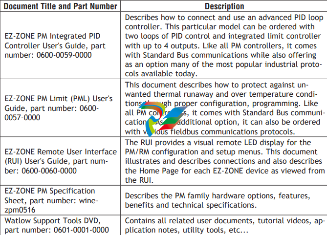
The DVD described above ships with the product and as stated contains all of the literature
above as well as much more. If the DVD is not available one can be acquired by contacting
Watlow Customer Service at 1-507-454-5300.
As an alternative to the DVD, all of the user documentation described above can also be
found on the Watlow website. Click on the following link to find your document of choice:
http://www.watlow.com/literature/index.cfm. Once there, simply type in the desired part
number (or name) into the search box and download free copies. Printed versions of all user
documents can also be purchased here as well.
Your Comments are Appreciated
In an effort to continually improve our technical literature and ensure that we are providing
information that is useful to you, we would very much appreciate your comments and suggestions. Please send any comments you may have to the following e-mail address:
TechlitComments@watlow.com
Introduction
The EZ-ZONE® PM takes the pain out of solving your thermal loop requirements. Watlow’s
EZ-ZONE PM controllers offer options to reduce system complexity and the cost of control
loop ownership. You can order the EZ-ZONE PM as a PID controller or an over-under limit
controller, or you can combine both functions in the PM Integrated Controller. You now have
the option to integrate a high-amperage power controller output, an over-under limit controller and a high-performance PID controller all in space saving, panel-mount packages. You
can also select from a number of industrial serial communications options to help you manage system performance.
Standard Features and Benefits
Advanced PID Control Algorithm
• TRU-TUNE+® Adaptive tune provides tighter control for demanding applications.
• Auto Tune for fast, efficient start ups
High-amperage Power Control Output
• Drives 15 amp resistive loads directly
• Reduces component count
• Saves panel space and simplifies wiring
• Reduces the cost of ownership
EZ-ZONE configuration communications and software
• Saves time and improves the reliability of controller set up
Parameter Save & Restore Memory
• Reduces service calls and down time
Agency approvals: UL Listed, CSA, CE, RoHS, W.E.E.E. FM
• Assures prompt product acceptance
• Reduces end product documentation costs
• Semi F47-0200
P3T Armor Sealing System
• NEMA 4X and IP65 offers water and dust resistance, can be cleaned and washed down (indoor use only)
• Backed up by UL 50 independent certification to NEMA 4X specification
Three-year warranty
• Demonstrates Watlow’s reliability and product support
Touch-safe Package
• IP2X increased safety for installers and operators
Removable cage clamp wiring connectors
• Reliable wiring, reduced service calls
• Simplified installation
EZ-Key/s
• Programmable EZ-Key enables simple one-touch operation of repetitive user activities
Programmable Menu System
• Reduces set up time and increases operator efficiency
Full-featured Alarms
• Improves operator recognition of system faults
• Control of auxiliary devices
Heat-Cool Operation
• Provides application flexibility with accurate temperature and process control
Profile Capability
• Pre-programmed process control
• Ramp and soak programming with four files and 40 total steps
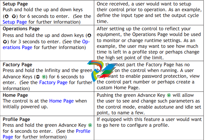
Getting Started Quickly
The PM control has a page and menu structure that is listed below along with a brief description of its purpose.
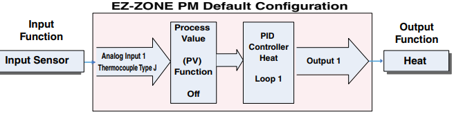
The default PM loop configuration from the factory is shown below:
• Analog Input functions set to thermocouple, type J
• Heat algorithm set for PID, Cool set to off
• Output 1 set to Heat
• Control mode set to Auto
• Set point set to 75 °F
If you are using the input type shown above, simply connect your input and output devices
to the control. Power up the control and push the up arrow ¿ on the face of the control to
change the set point from the default value of 75°F to the desired value. As the Set Point
increases above the Process Value, output 1 will come on and it will now begin driving your
output device. The PV function as shown in the graphic below is only available with PM4/8/9
models.
Note:
The output cycle time will have a bearing on the life of mechanical relay outputs and can
be different based on the type of output ordered. The output cycle time can be changed
in the Setup Page under the Output Menu.
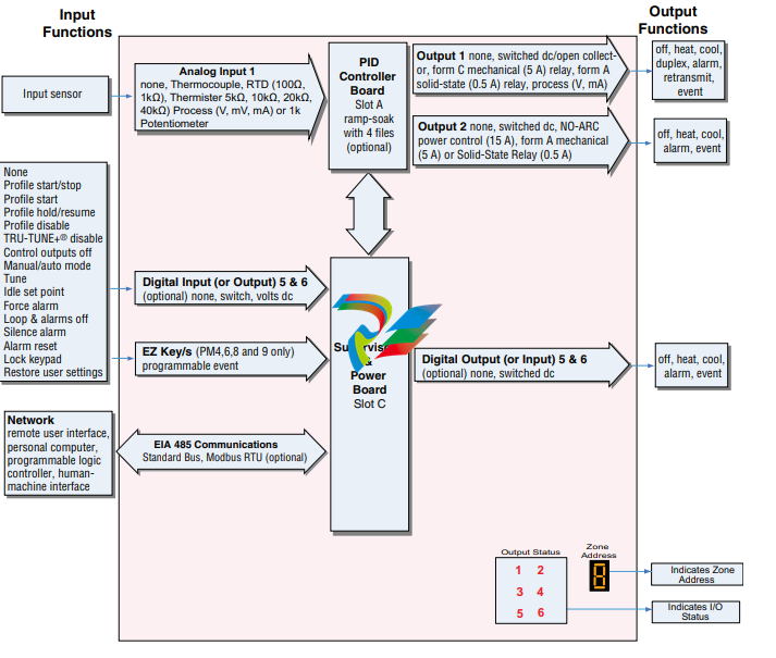
A Conceptual View of the PM
The flexibility of the PM’s software and hardware allows a large range of configurations. Acquiring a better understanding of the controller’s overall functionality and capabilities while
at the same time planning out how the controller can be used will deliver maximum effectiveness in your application.
It is useful to think of the controller in three parts: inputs; procedures; and outputs. Information flows from an input to a procedure to an output when the controller is properly
configured. A single PM controller can carry out several procedures at the same time, for
instance closed-loop control, monitoring for several different alarm situations and operating
switched devices, such as lights and motors. Each process needs to be thought out carefully
and the controller’s inputs, procedures and outputs set up properly.
Inputs
The inputs provide the information that any given programmed procedure can act upon. In a
simple form, this information may come from an operator pushing a button or from a sensor
monitoring the temperature of a part being heated or cooled.
Each analog input typically uses a thermocouple or RTD to read the process temperature. It
can also read volts, current or resistance, allowing it to use various devices to read a wide
array of values.
A PM with digital input/output (DIO) hardware includes two sets of terminals where each of
which can be used as either an input or an output. Each pair of terminals must be configured
to function as either an input or output with the direction parameter in the Digital Input/
Output Menu (Setup Page). Each digital input reads whether a device is active or inactive.
The Function or EZ Key/s (PM4/6/8/9 only) on the front panel of the PM also operates as a
digital input by toggling the function assigned to it in the Digital Input Function parameter in
the Function Key Menu (Setup Page).
Internal Functions
The controller will use input signals to calculate a value and then perform an operation. A
sample of some functions may be as simple as:
• Compare an input value to the set point and calculate the optimal power for a heater
• Detect a failure of the primary sensing device and trip a contactor to remove power from
the heating element
• Reading a digital input to set a state to true or false
• Evaluate an incoming temperature to determine an alarm state (on or off)
To set up a function, it’s important to define the source, or instance, to use. For example, if
the control is equipped with DIO they can be configured to respond to an alarm. If configured
as such, the digital output must be tied to the desired alarm instance (1 to 4). Using this as
an example, the Function for the digital output would be defined as an Alarm where the Instance would be selected as 1, 2, 3, or 4 corresponding to the alarm instance that will drive
the output.
Keep in mind that a function is a user-programmed internal process that does not execute
any action outside of the controller. To have any effect outside of the controller, an output
must be configured to respond to a function..
Outputs
Outputs can perform various functions or actions in response to information provided by a
function such as, removal of the control voltage to a contactor; operating a heater, turning a
light on or off, unlocking a door, etc...
Assign a Function to any available output on the Setup Page within the Output Menu or Digital Input/Output Menu. Then select which instance of that function will drive the selected
output. For example, you might assign an output to respond to alarm 4 (instance 4).
You can assign more than one output to respond to a single instance of a function. For example, alarm 2 could be used to trigger a light connected to output 1 and a siren connected
to digital output 5.
Input Events and Output Events
Input and output events are internal states that are used exclusively by profiles. The source
of an event input can come from a real-world digital input or an output from another function. Likewise, event outputs may control a physical output such as an output function block
or be used as an input to another function.
What is a Profile
A profile is a set of instructions consisting of a sequence of steps. When a profile runs, the
controller automatically executes its steps in sequence. The step type determines what action the controller performs. Steps can change temperatures and other process values gradually over time, maintain the temperatures and process values for specific periods, or repeat
a sequence of steps numerous times. At each step the profile can activate or deactivate
outputs that control other equipment. Also a step can have the controller wait for specific
conditions before proceeding such as, waiting for a switch closure and/or a specific process
value to be detected by a sensor.
EZ-ZONE® PM PID Model System Diagram
Universal Sensor Input, Configuration Communications,
Red/Green 7-Segment Display
Chapter 2: Install and Wire
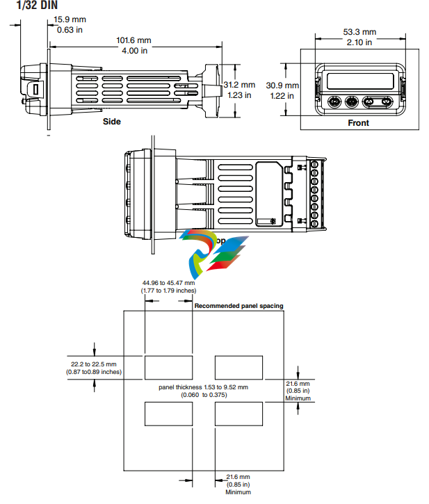
Installation
1. Make the panel cutout using the mounting template dimensions in this chapter. Insert the
case assembly into the panel cutout.
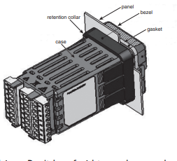
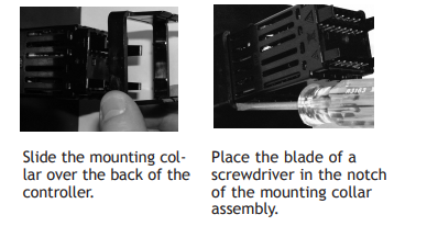
2. While pressing the case assembly firmly
against the panel, slide the mounting collar
over the back of the controller.
Note:
If the installation does not require a NEMA 4X
seal, simply slide together until the gasket is
compressed.
3. For a NEMA 4X (UL50, IP65) seal, alternately
place and push the blade of a screwdriver
against each of the four corners of the mounting collar assembly. Apply pressure to the face
of the controller while pushing with the screwdriver. Don't be afraid to apply enough
pressure to properly install the controller. The seal system is compressed more by mating
the mounting collar tighter to the front panel (see pictures above). If you can move the
case assembly back and forth in the cutout, you do not have a proper seal.
The tabs on each side of the mounting collar have teeth that latch into the ridges on the
sides of the controller. Each tooth is staggered at a different depth from the front so that
only one of the tabs, on each side, is locked onto the ridges at a time.
Note:
There is a graduated measurement difference between the upper and lower half of the
display to the panel. In order to meet the seal requirements mentioned above, ensure
that the distance from the front of the top half of the display to the panel is 16 mm
(0.630 in.) or less, and the distance from the front of the bottom half and the panel is
13.3 mm (0.525 in.) or less.
Removing the Mounted Controller from Its Case
From the controller's face, pull out the tabs on each side until you hear it click
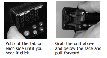
2. On a PM6 control once the sides are released grab the unit above and below the face with
two hands and pull the unit out. On the PM4/8/9 controls slide a screwdriver under the
pry tabs and turn.
WARNING! ç
• This equipment is suitable for use in class 1, div. 2, Groups A, B, C and D or Non-Hazardous
locations only. Temperature Code T4A.
• WARNING – EXPLOSION HAZARD. Substitution of component may impair suitability for class 1,
div. 2.
• WARNING – EXPLOSION HAZARD. Do not disconnect equipment unless power has been
switched off or the area is known to be nonhazardous.
Returning the Controller to its Case
1. Ensure that the orientation of the controller is correct and slide it back into the housing.
Note:
The controller is keyed so if it feels that it will not slide back in do not force it. Check the
orientation again and reinsert after correcting.
2. Using your thumbs push on either side of the controller until both latches click.
Chemical Compatibility
This product is compatible with acids, weak alkalis, alcohols, gamma radiation and ultraviolet radiation. This product is not compatible with strong alkalis, organic solvents, fuels,
aromatic hydrocarbons, chlorinated hydrocarbons, esters and keytones.
WARNING! ç
All electrical power to the controller and controlled circuits must be disconnected before
removing the controller from the front panel or disconnecting other wiring. Failure to follow
these instructions may cause an electrical shock and/or sparks that could cause an explosion
in class 1, div. 2 hazardous locations.
Default Home Page Parameters
Watlow's patented user-defined menu system improves operational efficiency. The userdefined Home Page provides you with a shortcut to monitor or change the parameter values
that you use most often. The default Home Page is shown on the following page. When a parameter normally located in the Setup Page or Operations Page is placed in the Home Page,
it is accessible through both. If you change a parameter in the Home Page, it is automatically
changed in its original page. If you change a parameter in its original page it is automatically
changed in the Home Page.
Use the Advance Key ‰ to step through the other parameters. When not in pairs, the parameter prompt will appear in the lower display, and the parameter value will appear in the
upper display. You can use the Up ¿ and Down ¯ keys to change the value of writable parameters, just as you would in any other menu.
Note:
If a writable value is placed on the upper display and is paired with another read only
parameter on the lower display, the arrow keys affect the setting of the upper display. If
two writable parameters are paired, the arrow keys affect the lower display.
• The Attention attn parameter appears only if there is an active message. An example of
an active message could be a Input Error Er.i1, or it could be for information only like
Autotune tUn1 taking place.
• If Control Mode is set to Auto, the Process Value is in the upper display and the Set Point
(read-write) is in the lower display.
• If a profile is running, the process value is in the upper display and the Target Set Point
(read only) is in the lower display. If Control Mode is set to Manual, the Process Value is in
the upper display and Manual Power (read-write) is in the lower display.
• If Control Mode is set to Off, the Process Value is in the upper display and off (read only)
is in the lower display.
• If a sensor failure has occurred, dashes ---- will be displayed in the upper display and
the Manual Power (read-write) is in the lower display
-
 HIRSCHMANN MSM20-M2M2M2M2SY9HH9E Ethernet media modul
 -
 HIRSCHMANN SPIDER-PL-20-05T1999999TWVHHHH Industrial Ethernet Rail Switch
 -
 Hirschmann SPIDER-PL-20-07T1M2M299TWVHHHH Industrial ETHERNET Rail Switch
 -
.png) Hirschmann (Belden) RS20-1600M2M2SDAEHC09.1.00 DIN-rail managed industrial Fast Ethernet switch
Hirschmann (Belden) RS20-1600M2M2SDAEHC09.1.00 DIN-rail managed industrial Fast Ethernet switch -
 Hirschmann (Belden) RS30-1602O6O6TDAPHC09.1.00 DIN-rail managed industrial Ethernet switch
 -
 Hirschmann (Belden) RS30-2402O6T1SDAPHH09.0.13 DIN-rail industrial Ethernet switch
 -
Hirschmann (Belden) SPIDER-PL-20-04T1S29999TY9HHHH Ethernet DIN-rail switch
-
 HIRSCHMANN RS20-1600T1T1SDAUHX Switch
 -
 HIRSCHMANN BRS42-0012OOOO-SPCZ99HHSES industrial switch
 -
 Hirschmann RS20-0800S2S2TDHPHH09.0.14 Fast Ethernet DIN rail switch.
 -
 HIRSCHMANN MM20-Z6Z6M2M2SAHH Hybrid Fast Ethernet Media Module
 -
 HIRSCHMANN MM20-Z6Z6T1T1SAHH hot-swappable hybrid Fast Ethernet Media Module
 -
 HIRSCHMANN MM20-P9P9T1T1SAHH Hybrid Fast Ethernet Media Module
 -
 HIRSCHMANN MM20-M4T1T1T1SAHH Hybrid Fast Ethernet Media Module
 -
 HIRSCHMANN MM20-M4M4T1T1SAHH Hybrid Fast Ethernet Media Module
 -
 HIRSCHMANN MM20-M2M2M2M2SZHH Ethernet media module
 -
HIRSCHMANN MM20-M2M2M2M2SAHH Ethernet media module
-
 HIRSCHMANN MM20-T1T1T1T1EBH 4-port Fast Ethernet Copper Cable Media Module
 -
HIRSCHMANN MM20-T1T1T1T1SAHH 4-port Fast Ethernet Copper Cable Media Module
-
HIRSCHMANN MM20-T1T1T1T1SAHH 4-port Fast Ethernet Copper Cable Media Module
-
 HIRSCHMANN MM20-Z6Z6EBH Hot-swappable fast Ethernet media module
 -
 HIRSCHMANN MM20-Z6Z6SAHH Ethernet media module
 -
HIRSCHMANN MM20-Z6Z6Z6Z6EBH Industrial Media Module
-
 MSM40-T1T1T1TZ9HH9E99.9.99 HIRSCHMANN Switch
 -
 HIRSCHMANN MS20-0800SAAEHC / MS20-0800SAAEHC0 8-port modular Layer 2 management Ethernet switch
 -
 Hirschmann RSPM20-4T14T1SZ9HHS9 Switch RSPM20-4T14T1SZ9HHS9
 -
 HIRSCHMANN RS20-1600M2M2SDAEHH09.1. RS20/30/40 Managed Switch configurator
 -
HIRSCHMANN RS20-1600M2M2SDAEHX09.0.00 Ethernet switch
-
 HIRSCHMANN BELDEN SPIDER-PL-20-07T1M2M299TY9HHHH / SPIDERPL2007T1M2M299TY9HHHH
 -
HIRSCHMANN MM3-1FXS2/3TX1 Switching Board Module
-
 HIRSCHMANN RSPE30-24044O7T99-ECCP999HHSE2A08.1.00 Industrial-grade fanless management-type Ethernet switch
 -
 HIRSCHMANN RS30-1602OOZZSDAEHC09.1.00 DIN-rail-mounted managed Layer 2 Ethernet switch
 -
 HIRSCHMANN MACH104-20TX-F Managed 24-port Full Gigabit 19" Switch
 -
 HIRSCHMANN Switch RS20-0800M4M4SDAE
 -
Hirschmann RS30-1602O6O6SDAEHH09.1. Management-type Ethernet switch
-
 Hirschmann RS30-1602OOZZSDAEHC09.0.10 Open rack-style Ethernet switch
 -
 HIRSCHMANN RSPE30-24044O7T99-SCCV999HHSI2SXX.X.XX High-Availability Seamless Redundancy
 -
HIRSCHMANN RSPE30-24044O7T99-SCCZ999HHSE2A DIN-rail Ethernet switch
-
HIRSCHMANN MM2-4TX1-EEC switch
-
HIRSCHMANN MSM40-T1T1T1T1TZ9HH9E99.9.99 Module
-
 HIRSCHMANN RS20 Rail Switch RS20-0400S4T1SDAEHC07.1.01
 -
 HIRSCHMANN M4-FAST8-SFP Fast Ethernet media module
 -
 HIRSCHMANN RS20-0400M2T1SDAP Managed Fast-Ethernet-Switch
 -
 HIRSCHMANN BELDEN SPIDER II 8TX/1FX EEC Industrial Ethernet Rail Switch
 -
HIRSCHMANN MM3-2FXS2/2TX1
-
 HIRSCHMANN RS2-4TX/1FX EEC Industrial Ethernet Rail Switch
 -
 RS30-0802O6O6SDAEHC09.0.10 HIRSCHMANN Switch
 -
 HIRSCHMANN m4-8TP-RJ45 Ethernet Media Module
 -
 HIRSCHMANN MSP30-24040SCZ9URHHE3A switch
 -
 Hirschmann rack MS30-1602SAAPHC
 -
 HIRSCHMANN RS2-FX/FX Industrial Switch Module
 -
Rs1txfx - Hirschmann - Rs1-Tx/Fx Rail Switch
-
RS20-0800S2S2SDAEHC09.1.00 HIRSCHMANN Commutator
-
 Hirschmann EAGLE20 TX/TX Industrial Security Router
 -
 Hirschmann SPIDER-SL-20-04T1S29999SY9HHHH Industrial Switch
 -
 HIRSCHMANN MAR1040-4C4C4C4C9999SMMHRHHXX.X. Gigabit Ethernet Switch configurator
 -
 Hirschmann MAR1040 Industrial Switch
 -
 HIRSCHMANN BELDEN RS30-1602O6O6SDAE
 -
Hirschmann RS20-1600M2M2SDAUHC Ethernet DIN rail switch
-
 HIRSCHMANN OCTOPUS 24M industrial switch
 -
 HIRSCHMANN RS20-1600T1T1SDAE Management-type Ethernet switch
 -
 HIRSCHMANN RS20-1600T1T1SDAUHH industrial switch
 -
HIRSCHMANN RS20-0800M2M2SDAPHC09.0.04 switch
-
 Hirschmann MR 8-03 24V DC Industrial Modular Bridge/Router
 -
 HIRSCHMANN RS20-0400M2T1SDAPHC08.0.01 Managed Switch
 -
 MACH1130 Hirschmann Industrial Switch
 -
 HIRSCHMANN 943824-002 SPIDER 5TX Industrial Ethernet Switch
 -
 HIRSCHMANN RS30-0802O6O6SDAEHC09.1.00 Managed Industrial Switch
 -
 HIRSCHMANN RS20-0400M2M2TDAEHC04.0.01 Industrial Switch
 -
 HIRSCHMANN BRS20-0600Z6Z6-STCZ99HHSES Industrial Switch
 -
 HIRSCHMANN MACH104-20TX-FR-L3P Industrial Ethernet Switch
 -
 HIRSCHMANN RS40-0009CCCCEDBPHH06.0.01 Industrial Switch
 -
 HIRSCHMANN RS2-3TX/2FX EEC Industrial Ethernet Switch
 -
 Hirschmann MACH 1020/1030 Fast/Gigabit Rack Mount Switches
 -
HIRSCHMANN RS20-0800M2M2SDAPHC09.0.14 Industrial Switch
-
 HIRSCHMANN RS20-1600T1T1SDAEHC09.0.04 Industrial Switch
 -
 HIRSCHMANN RSB20-0800T1T1EAABHH Industrial Switch
 -
 HIRSCHMANN MACH4002-48+4G-L3E Industrial Backbone Switch
 -
 HIRSCHMANN RS20-0400S2T1SDAE Industrial Managed Switch
 -
HIRSCHMANN RS20-0800S2T1SDAUHC Industrial Switch
-
 HIRSCHMANN RS20-2400S4S4SDAEHC09.0.14 industrial switch
 -
 HIRSCHMANN OS20-001200T5T5T5- TBBZ999HHNE3S 08.1.00 industrial switch
 -
HIRSCHMANN OS20-001200T5T5T5- TBBZ999HHNE3S 08.1.00 industrial switch
-
 HIRSCHMANN RS40-0009CCCCSDAEHH09.0.14 switch
 -
 Hirschmann RS20-1600T1T1SDAUHC Management-type Ethernet Switch
 -
 Hirschmann M1-8SFP Switche
 -
Hirschmann Industrial Ethernet Ruggedized Switch MACH1000 Family
-
 Basler Electric, Solid State Protective Relay, BE1-60
 -
BASLER ELECTRIC SR4A-2B15B3A Static Voltage Regulator
-
.png) BASLER ELECTRIC EXCITER DIODE MONITOR EDM-200
BASLER ELECTRIC EXCITER DIODE MONITOR EDM-200 -
.png) BASLER ELECTRIC DECS125-15-B2C5 DIGITAL EXCITATION CONTROL SYSTEM V 2.0.9
BASLER ELECTRIC DECS125-15-B2C5 DIGITAL EXCITATION CONTROL SYSTEM V 2.0.9 -
 BASLER ELECTRIC BE1-851 OVERCURRENT PROTECTION RELAY MECHANISM
 -
 Basler Electric BE1-51A / BE151A
 -
 Basler Electric BE1-40Q Loss of Excitation Relay
 -
 Basler Electric BE1-87G Variable Percentage Differential Relay
 -
 Basler Electric BE1-11 Protection System I5A3M2P2N0EA00
 -
 BASLER ELECTRIC DECS-200-1C Digital Excitation Control System
 -
 Basler Electric / Kohler BE1-11g Generator Protection Relay G5A3M2J2N0E000
 -
BASLER ELECTRIC DECS125-15 DIGITAL EXCITATION CONTROL SYSTEM
-
 BASLER ELECTRIC BE1-951 OverCurrent Protecton System
 -
Basler Electric DECS-200-1L Digital Excitation Control System
-
 Basler Electric DGC-2020HD-5NS1DNSBA Digital Genset Controller -
 -
 BASLER ELECTRIC BE1-81T1EE1WA0N1F / BE181T1EE1WA0N1F
 -
 BASLER ELECTRIC BE1-25M1EA6PN5R1F / BE125M1EA6PN5R1F
 -
 BASLER ELECTRIC DECS-250-LN1SN1N DIGITAL EXCITATION CONTROL SYSTEM
 -
Basler Electric DECS-250-CN2CN 1N Digital Excitation Control System Unit
-
 BASLER ELECTRIC DECS-300-C0N0 DIGITAL EXCITATION CONTROL SYSTEM
 -
 BASLER ELECTRIC BE1-87T-A1E-A1J-D0S1F / BE187TA1EA1JD0S1F
 -
BASLER ELECTRIC BE1-11-G6D1M0J2P0E000 Protection System
-
 BASLER ELECTRIC BE1-GPS100-E4N1H1N GENERATOR PROTECTION SYSTEM
 -
 Jaquet Relay card (Auxiliary module) FTV 3090 377Z-03985
 -
 Jaquet Trip Chain Control card FTBU 3034 377Z-05030
 -
 Jaquet with input card -E04 FTFU 3024 -E04 377Z-05855
 -
 Jaquet with input card -E03 FTFU 3024- E03 377Z-03983
 -
 Jaquet FTFU 3024- E02 377Z-03982 with input card -E02
 -
 Jaquet FTFU 3024-E01 377Z-03981 with input card -E01
 -
 Hirschmann RS20-2400T1T1SDAE Industrial Managed Ethernet Switch
 -
 Hirschmann BELDEN EAGLE30-04022O6TT999SCCV9HSE3F
 -
 Hirschmann MM3-2FXS2/2TX MICE Media Module
 -
 Hirschmann RS20-1600M2M2SDAPHC08.0.05 Industrial Managed Switch
 -
 Hirschmann OZD Profi 12M G12-1300 PRO Fieldbus Repeater
 -
Hirschmann SPIDER 4TX/1FX-ST EEC Industrial Ethernet Switch
-
 Hirschmann MM2-2FXM3/2TX1 MICE Media Module
 -
 Hirschmann RS20-2400M2M2SDAPHC09.0.14 Industrial Switch
 -
 Hirschmann RS20-0400M2M2SDAEHC07.1.05 OpenRail Switch
 -
 Hirschmann OZD Profi 12M G12-EEC Fieldbus Repeater
 -
HIRSCHMANN MDA422-1/2-3.5c-23/46 sensor
-
Hirschmann RS30-2402T1T1SDAUHC Managed Industrial Switch


