
ABBAC 800M PROFIBUS DP Configuration
NOTICE
This document contains information about one or more ABB products and may include a
description of or a reference to one or more standards that may be generally relevant to
the ABB products. The presence of any such description of a standard or reference to a
standard is not a representation that all of the ABB products referenced in this document
support all of the features of the described or referenced standard. In order to determine
the specific features supported by a particular ABB product, the reader should consult the
product specifications for the particular ABB product.
ABB may have one or more patents or pending patent applications protecting the intellectual property in the ABB products described in this document.
The information in this document is subject to change without notice and should not be
construed as a commitment by ABB. ABB assumes no responsibility for any errors that
may appear in this document.
In no event shall ABB be liable for direct, indirect, special, incidental or consequential
damages of any nature or kind arising from the use of this document, nor shall ABB be
liable for incidental or consequential damages arising from use of any software or hardware described in this document.
This document and parts thereof must not be reproduced or copied without written permission from ABB, and the contents thereof must not be imparted to a third party nor used
for any unauthorized purpose.
The software or hardware described in this document is furnished under a license and
may be used, copied, or disclosed only in accordance with the terms of such license. This
product meets the requirements specified in EMC Directive 2004/108/EC and in Low Voltage Directive 2006/95/EC.
TRADEMARKS
All rights to copyrights, registered trademarks, and trademarks reside with their respective owners.
Copyright © 2003-2013 by ABB.
All rights reserved.
Release: December 2013
Document number: 3BDS009030-510 A
This user manual describes the configuration of the PROFIBUS DP-V1 in the
800xA control system using the communication interface CI854/CI854A.
The main areas covered in this user manual are:
• PROFIBUS functionalities available with CI854/CI854A,
• Hardware configuration with the Control Builder M,
• Supervision and status visualization of the PROFIBUS.
The reader of this manual is expected to have good knowledge of the 800xA control
system and the PROFIBUS in general.
This user manual is not the only source of instruction for PROFIBUS. ABB offers
training courses for those who use ABB control systems.
Any security measures described in this User Manual, for example, for user
access, password security, network security, firewalls, virus protection, etc.,
represent possible steps that a user of an 800xA System may want to consider
based on a risk assessment for a particular application and installation. This risk
assessment, as well as the proper implementation, configuration, installation,
operation, administration, and maintenance of all relevant security related
equipment, software, and procedures, are the responsibility of the user of the
800xA System.
This manual does not provide any information on the use and configuration of the
PROFIBUS bus communication interface module CI851. This information is
found in the online help of Control Builder M.
It also does not provide any information about installing the PROFIBUS network.
This information is provided in the AC 800M PROFIBUS DP Installation manual
(3BDS009029*) for PROFIBUS DP-V1.
Intended User
This manual is intended for application engineers and for engineers who are
planning the design of a PROFIBUS system. The reader should be familiar with
Control IT for AC 800M products and the programming tool, Control Builder M.
Also the reader should be familiar with the hardware and software functionality of
the 800xA system products. Apart from this, the user should have a good
PROFIBUS knowledge.
How to Use this User Manual
Section 1, Introduction gives a brief overview of PROFIBUS and how it is
integrated in the controllers.
Section 2, Functional Description provides detailed information on the PROFIBUS
implementation.
Section 3, Configuration describes the configuration of PROFIBUS with the Control
Builder M.
Section 4, Download and Online Mode describes the download procedure and the
system behavior in case of an error.
Section 5, Web Interface describes how to get detailed diagnostic information from
the system in case of a serious PROFIBUS error and how to set the slave address for
PA devices.
For a list of documentation related to the products described in this user manual, see
Released User Manuals and Release Notes on page 17.
User Manual Conventions
Microsoft Windows conventions are normally used for the standard presentation of
material when entering text, key sequences, prompts, messages, menu items, screen
elements, etc.
Warning, Caution, Information, and Tip Icons
This User Manual includes Warning, Caution, and Information where appropriate to
point out safety related or other important information. It also includes Tip to point
out useful hints to the reader. The corresponding symbols should be interpreted as
follows:
Although Warning hazards are related to personal injury, and Caution hazards are
associated with equipment or property damage, it should be understood that
operation of damaged equipment could, under certain operational conditions, result
in degraded process performance leading to personal injury or death. Therefore,
fully comply with all Warning and Caution notices.
Terminology
A complete and comprehensive list of Terms is included in the IndustrialIT
Extended Automation System 800xA, Engineering Concepts instruction
(3BDS100972*). The listing includes terms and definitions that apply to the 800xA
System where the usage is different from commonly accepted industry standard
definitions and definitions given in standard dictionaries such as Webster’s
Electrical warning icon indicates the presence of a hazard that could result in
electrical shock.
Warning icon indicates the presence of a hazard that could result in personal
injury.
Caution icon indicates important information or warning related to the concept
discussed in the text. It might indicate the presence of a hazard that could result
in corruption of software or damage to equipment/property.
Information icon alerts the reader to pertinent facts and conditions.
Tip icon indicates advice on, for example, how to design your project or how to
use a certain function
Released User Manuals and Release Notes
A complete list of all User Manuals and Release Notes applicable to System 800xA
is provided in System 800xA Released User Manuals and Release Notes
(3BUA000263*).
System 800xA Released User Manuals and Release Notes (3BUA000263*) is
updated each time a document is updated or a new document is released. It is in pdf
format and is provided in the following ways:
• Included on the documentation media provided with the system and published
to ABB SolutionsBank when released as part of a major or minor release,
Service Pack, Feature Pack, or System Revision.
• Published to ABB SolutionsBank when a User Manual or Release Note is
updated in between any of the release cycles listed in the first bullet.
For standards and commercially available PROFIBUS documentation please visit
the PROFIBUS Web Site (http://www.profibus.com).
A product bulletin is published each time System 800xA Released User Manuals
and Release Notes (3BUA000263*) is updated and published to ABB
SolutionsBank.
General Overview
PROFIBUS is a manufacturer-independent fieldbus standard for applications in
manufacturing, process and building automation. PROFIBUS technology is
described in fixed terms in DIN 19245 as a German standard and in EN 50170 / IEC
61158 as an international standard. The PROFIBUS standard is thus available to
every provider of automation product.
The PROFIBUS family is composed of three types of protocol, each of which is
used for different tasks. Of course, devices with all three protocols can communicate
with each other in a complex system by means of a PROFIBUS network.
The three types of protocols are: PROFIBUS FMS, DP and PA.
Only the two protocol types DP and PA are important for process automation.
PROFIBUS DP: the bus for the decentralized periphery
The PROFIBUS DP (RS 485) is responsible for communication between the
Controller level of a process automation system and the decentralized periphery in
the field, also intrinsic safety (RS485-IS) via DP-Ex barriers into hazardous area.
One feature of PROFIBUS DP is its high speed of transmission up to 12 Mbit/s.
PROFIBUS PA: extension for process automation
This PROFIBUS variant was developed for the process industry. Communication
and power supply to Transmitter and Positioners are handled direct via one 2-line
cable and correspond to IEC Standard 61158-2 (named also as MBP, MBP-LP).
Intrinsic safety (EEx i) (MBP-IS) installations in Zone 1 / Div.1 are possible.
Coupling components (Linking Devices) are used to integrate PA bus lines into the
PROFIBUS DP network. This ensures that all information is available in a
continuously connected network through the complete PROFIBUS system (DP and
PA).
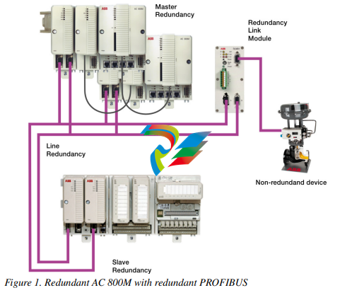
The PROFIBUS DP is interfaced to the IEC61131 controller AC 800M using the
PROFIBUS DP-V1 module CI854/CI854A in the AC800M. For high availability
redundancy is supported.
The configuration for the PROFIBUS is done with the Control Builder M. The
configuration covers the planning of the HW units in the HW tree and the device
specific configuration for the master and slave units as well. The device specific
configuration data is described within the device specific GSD File provided by the
manufacturer of the device. To allow the configuration of the device within the
Control Builder M the GSD File has to be converted to a HWD File and inserted to
the project. The conversion is done with the GSD Import Tool.
The following figure shows the redundant PROFIBUS connected to the redundant
AC 800M controller
Section 2 Functional Description
PROFIBUS Basics
Basic Functions DP-V0
Cyclic Data Communication
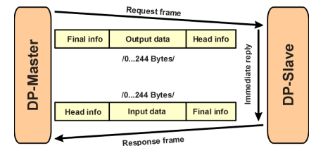
The data communication between the DPM1 (DP Master Class 1) and its assigned
slaves is automatically handled by the DPM1 in a defined, recurring sequence. With
each user data transfer, the master can write up to 244 bytes of output data to the
slave and read up to 244 bytes of input data from the slave. The Data is read and
written synchronously in one procedure
The assignment of the slaves to the DPM1, CI854/CI854A in this case, is done via
the HW configuration in Control Builder M.
The data communication between the DPM1 and the slaves is divided into three
phases: parameterization, configuration and data transfer. Before the master
includes a DP slave in the data transfer phase, a check is run during the
parameterization and configuration phase to ensure that the configured setpoint
configuration matches the actual device configuration. During this check, the device
type, format and length information and the number of inputs and outputs must also
correspond. This provides you with reliable protection against parameterization
errors.
Diagnostics
In addition to the cyclic data the PROFIBUS slave unit provides diagnostic data.
With this diagnostic data the slave can indicate errors or warnings on the slave unit,
the I/O-units or the I/O-channels. Some diagnostic data is generic and defined by the
PNO. But most of the diagnostic data is manufacturer specific.
The following errors/warnings are examples for PROFIBUS diagnostics:
Channel related:
– Wire break
– Short circuit
Module related:
– Wrong module type
– Module missing
Slave related:
– Power supply 2 error
– Internal bus error
The CI854/CI854A supports the operation of PROFIBUS DP-V0 diagnostics. The
diagnostic data transferred from the slave to the master is mapped by the
CI854/CI854A to the unit status of the PROFIBUS slave unit or the related I/O-unit
and is indicated as error or warning in the UnitStatus in Control Builder M for the
specific unit.
Only that diagnostic data configured within the hardware definition file is operated
by the system. The configuration includes
– Selection of diagnostic to be operated by the system.
– Mapping of the diagnostic information within the diagnostic frame on
PROFIBUS to the specific HW unit (slave or I/O unit).
– Definition of the corresponding bit in the unit status for the specific
diagnostic information. Use of device specific codes in
ErrorsAndWarnings and ExtendedStatus.
– Definition if the diagnostic information shall be indicated as error or
warning.
– Definition of the presented text within unit status and alarm/event for the
specific diagnostic information.
– Definition if in addition an alarm or event shall be generated for the
specific diagnostic information. If yes also the severity has to be defined.
For S800 I/O and S900 I/O the configuration for the diagnostics is already specified
in the hardware definition files that are provided with the system. For other slaves
the configuration for PROFIBUS diagnostics can be done via the DeviceImport
Wizard. The Device Import Wizard provides a dialog to pick up the diagnostic data
from the GSD-file and map it to the DeviceSpecific and ExtendedStatus bits of the
HwStatus for the related slave unit or I/O-unit. The dialog also supports the
configuration of alarms/events based on the diagnostic data. For more information
please refer to the online help for the GSD Import Tool.
DP Master Class 1 (DPM1) and Class 2 (DPM2)
TheDP master class 1 is the master that is in cyclic data transmission with the
assigned slaves. To get into the cyclic communication the DPM1 has to configure
the slave before.
The DP master class 2 is used for engineering and configuration. It does not have
cyclic data transmission with the slave devices. Normally a DPM2 is only connected
temporarily to the bus. A DPM2 can have class 2 communication to the slave
devices before the slaves are configured via DPM1 and cyclic communication is
active.
System Behavior
For a DPM1 master the following operating states are defined:
Stop
No data communication between the DPM1 and the slaves.
The CI854/CI854A is of type DP master class 1 (DPM1) and class 2 (DPM2).
Clear
The DPM1 reads the input information of the slaves and keeps the outputs of the
slavs in a fail-safe state (“0” output).
Operate
The DPM1 is in the data transfer phase. In cyclic data communication, inputs are
red from the slaves and output information written to the slaves.
The reaction of the system to a fault during the data transfer phase of the DPM1, for
example a failure of a slave, is determined by the “Auto Clear Modus” defined via
the BP flag configuration in the settings tab for CI854/CI854A. If this parameter is
enabled, the DPM1 switches the outputs of all assigned slaves to a fail-safe state the
moment a slave is no longer ready for user data transmission. The DPM1
subsequently switches to the clear state. If this parameter is disabled, the DPM1
retains in the operate state even in the event of a fault and the user can control the
reaction of the system. Please refer also to Settings Tab on page 49.
Sync and Freeze Mode
In addition to the normal cyclic communication between the DPM1 (DP Master
Class 1) and the assigned slaves, a master can send the control commands sync and
freeze via multicast to a group of slaves.
With the sync-command the addressed slaves will freeze the outputs in their current
state. New output values received by the master will be stored while the output
states remain unchanged. The stored output data are not sent to the outputs until the
next sync command is received. The Sync mode is terminated with the “unsync”
command.
In the same way, a freeze command causes the addressed slaves to enter freeze
mode. In this mode, the states of the inputs are frozen at their current value. The
input data are not updated again until the master sends the next freeze command.
Freeze mode is terminated with the “unfreeze” command.
The CI854/CI854A does not support sync and freeze mode
Monitoring the DP-V0 Communication
The cyclic communication between the DPM1 and the slaves is monitored by the
master and the slaves itself.
If the CI854/CI854A master unit detects a failure in the communication with a
slave, it will indicate the corresponding slave as disturbed. If enabled, Auto Clear
Modus will be activated. On CI854/CI854A a special handling is implemented to
support also redundancy for master and slave. In both cases the monitoring timings
consider the failovers of master and slave.
On slave side the communication with the master is controlled via the watchdog. If
no data communication with the master occurs within the watchdog control interval,
the slave automatically switches its outputs to the fail-safe state.
Please refer also to Connection Error on page 70
Multi Master Systems
In a multi master system several masters are connected to one bus. They represent
either independent subsystems, comprising one DPM1 (DP Master Class 1) and its
assigned slaves, or additional configuration and diagnosis devices. The
CI854/CI854A master unit supports multi master systems.
The Control Builder M with the integrated PROFIBUS master calculation does not
support multi master configurations. The calculation only covers one
CI854/CI854A with its assigned slaves. If you connect several CI854/CI854A or
additional configuration devices to the same bus you have to adapt the bus settings
manually. But only the TTR has to be adapted. An overall TTR has to be calculated
as the sum of all individual TTR for the CI854/CI854A master units connected to
the same PROFIBUS. The resulting TTR has to be manually configured for all
connected CI854/CI854A master units.
Example: you have three CI854/CI854A master units having the automatically
calculated TTR times 20.000, 30.000 and 40.000, then you have to manually
configure the TTR time 90.000 for all three units.
If a standalone tool is directly connected to the PROFIBUS as DPM2 (DP Master
Class 2) master for some acyclic communication, then the TTR time of this
master also has to be taken into account. Otherwise the standalone tool might get
communication problems
Acyclic Data Communication
The key feature of version DP-V1 is the extended function for acyclic data
communication. The acyclic data communication is mainly used for configuration
and parameterization purpose. With the acyclic DP-V1 read and write services the
master can read or write any desired data to and from the slave. The data is
addressed by slot, index and length. Each data block can be up to 244 bytes.
Figure 3. Acyclic Communication in DP-V1: Read Service
The transmission of acyclic data is executed in parallel to the cyclic data
communication, but with lower priority. Acyclic services are operated in the
remaining time at the end of the DP-V0 cycle.
The automatic master calculation for CI854/CI854A ensures that the gap on
PROFIBUS is big enough for some acyclic communication. If there is a need to
increase the gap for some additional acyclic communication this can be done via the
TTR time. Please refer also to Settings Tab on page 47.
Alarms and Status Messages
As a further function in DP-V1, the device specific diagnosis of the DP-V0 have
been enhanced and divided into the categories alarms and status messages. As the
major difference to the DP-V0 diagnosis, the alarms from the slave to the master are
transferred via confirmed services.
Redundancy
Overview
With PROFIBUS and CI854/CI854A you have a high scalability for redundancy.
You have the options to configure redundancy for:
• PROFIBUS master unit CI854A
• PROFIBUS slave unit
• PROFIBUS line.
Depending on your needs each type of redundancy can be configured independent
of each other. Also mixed configurations are supported. You can configure for
example a redundant PROFIBUS installation consisting of a redundant CI854A
master unit and redundant PROFIBUS lines and have connected redundant and nonredundant slave units in parallel.
A special mixture of redundancy is the so called combined slave and line
redundancy. A slave provides two slave units supporting the PNO slave redundancy
and each slave unit only provides one PROFIBUS interface. This is a one error
tolerant solution. The slave unit will only have communication on one PROFIBUS
line at a time and a single error on the PROFIBUS line will lead to a switchover of
the slave units. But the big advantage of this solution are the reduced cost. Therefore
it is a very popular solution. It is used for example for S800 I/O with CI840 and
S900 I/O with CI920.
Master Redundancy
The CI854A supports PROFIBUS master redundancy. Two CI854A connected to
one controller can be configured to work in a redundant configuration. The
configuration for redundancy is done via configuring the CI854A in the hardware
tree of the Project Explorer. For configuration of redundancy please refer to Add
Redundancy for Master Unit on page 41.
Primary and backup CI854A need different node addresses on PROFIBUS. While
the primary node address is configured via the settings in the HW Configuration
Editor the node address for the backup module is defined by the fixed offset -1 to the
node address of the primary module. Therefore you cannot configure the node
address 0 on PROFIBUS with CI854/CI854A. This is reserved for redundancy.
During normal operation only the primary CI854A has communication with the
slave units. The backup unit is in hotstandby mode. It is configured by the controller
and synchronized by the primary unit. If there is a failover because of for example a
disturbed PROFIBUS communication, primary and backup module change the node
addresses. During failover the former primary module will get reset.
After download and successful configuration the availability of the backup unit is
monitored. This includes the balancing of current data and the communication links
via PROFIBUS and CEX-Bus as well. In case of no error the DUAL LEDs on
primary and backup unit will be lit. If the backup unit is not ready to takeover the
DUAL LEDs will get off on both units. The error will be indicated in the unit status
and a potential redundancy switchover will be inhibited in this case.
Reasons to perform a switchover are for example that the primary unit has lost the
communication to all connected slaves “All slaves failed” because of for example a
cabling problems or a “Fatal error” on the primary CI854A itself was detected.
Slave Redundancy
The CI854/CI854A supports the PROFIBUS slave redundancy like specified by the
PROFIBUS User Organization (PNO). The specification can be found at
http://www.profibus.com.
A redundant slave has two PROFIBUS interfaces, one for the primary and one for
the backup slave. If line redundancy is used, one of the interfaces is connected to
line A and the other to line B. If not, both interfaces are connected to the same
PROFIBUS cable. The PROFIBUS address of the backup slave is always the
address of the primary slave plus 64. The configuration in the Control Builder
ensures, that both addresses are available when the slave is set redundant. If a
redundancy switchover of a slave occurs, also the PROFIBUS addresses are
switched. That means, the primary slave always has the assigned address and the
backup slave always has the address + 64 regardless of who is the primary and who
is the backup. This kind of redundancy is called "flying redundancy".
Only the primary slave can transfer process data and diagnostic information on the
PROFIBUS. Therefore the status of the primary slave also contains the information
of the backup slave. Please refer to the slave documentation for the details.
Although the backup slave has no active data transmission with the master the
CI854/CI854A is able to monitor the backup slave. The backup slave is available in
the Livelist and if redundancy is configured the monitoring will be activated. If the
backup slave fails, the information "Redundant slave does not exist" will be set in
the ExtendedStatus of the primary slave.
To allow the slave a failover in case of an error the CI854/CI854A has a special
monitoring function. If the redundant slave gets disturbed the CI854/CI854A waits
for (2* watchdog time + 1) before connection down will be indicated for the slave.
During this time the slave can perform a switchover and proceed with the normal
data exchange without interrupting the communication.
Line Redundancy
The CI854/CI854A supports line redundancy for PROFIBUS DP. Therefore the two
interfaces "PROFIBUS A" and "PROFIBUS B" are available on the baseplates
TP854 of the modules. There is a Redundancy Link Module functionality
implemented on the CI854/CI854A that handles the sending and receiving of data
on the PROFIBUS. Independent of any configuration the RLM sends data on both
lines and receives data only via one line. Regarding the receiving of data the RLM
checks if the slave sent data on both lines and if the data is valid. The first received
valid data on line A or B will be picked up and operated. It is possible that the slave
sends data on both lines in parallel or only on one line.
The monitoring of the line redundancy can be enabled or disabled. The default is
disabled. The enabling is done via the parameter "Line redundancy" in the settings
If the non-redundant slave gets disturbed the CI854/CI854A waits for watchdog
time before connection down will be indicated for the slave
for CI854/CI854A. If the line redundancy is enabled the warning "No activity on
PROFIBUS" will be indicated for the specific line in the case of a failure, for
example if there is a fault on the PROFIBUS cable.
Please enable the monitoring of line redundancy, if
– redundant slaves according to the PNO redundancy specification are used
and/or
– non-redundant slaves provide a line redundant interface and/or
– non-redundant slaves with only one PROFIBUS interface are connected to
the CI854/CI854A with a RLM01.
Status Handling
Status Handling for DP-V1 Master Unit
Every status information for CI854/CI854A in terms of hardware and software
errors is indicated via the unit status. The unit status is used to present the status of
the HW unit in Control Builder M while CBM is in online mode. In addition
alarms/events are generated based on the unit status (please refer also to Alarms and
Events on page 36). For special reasons also the access to the unit status via the
controller application is supported.
-
 Hirschmann RS20-1600M2T1SDAEHH03.1.02 Rail Switch
 -
 Hirschmann BRS30-24TX Industrial Rail Switch
 -
 Hirschmann RSPM20-4T14T1EV9HHS999.9.99 Managed Ethernet Switch
 -
 Hirschmann BELDEN RS40-0009CCCCSDAPHH09.0.14 / RS400009CCCCSDAPHH09014
 -
Hirschmann RS40 Rail Switch RS40-0009CCCCSDAE
-
 Hirschmann BELDEN RS30-0802T1T1SDAP / RS300802T1T1SDAP Fully Managed Layer 2 Compact Rail Switch
 -
 Hirschmann BELDEN RS20-0800M2M2SDAUHH / RS200800M2M2SDAUHH
 -
 Hirschmann EAGLE30-04022O6TT999SCCY9HSE3F Industrial Firewall Router Switch
 -
 Hirschmann RS20-1600T1T1SDAEHH09.0.14 RS20 Rail Mount Ethernet Switch
 -
 Hirschmann EAGLE0200T1T1TDDY90000HHE05.3.03 Industrial Security Router
 -
Hirschmann - BELDEN MIPP-AD-1L9P
-
 HIRSCHMANN RSPM20-4Z64Z6TV9HHS9 942 106-999 RAIL SAFETY SWITCH
 -
 HIRSCHMANN FIBEROPTIC MODULE FIP P/N: OZDFIPG3T
 -
 HIRSCHMANN RS20-1600M2M2SDAUHH Ethernet rack-mounted switch
 -
 HIRSCHMANN BELDEN RS20-0400T1T1SDAEHH04.0.01 / RS200400T1T1SDAEHH04001
 -
HIRSCHMANN MM2-4FXM3 MICE Media Module
-
HIRSCHMANN RS20-0800M2M2SDAE Industrial Ethernet Rail Switch
-
 Hirschmann RS20-2400T1T1SDAP / RS20-2400T1T1SDAPHH05.0.02
 -
 GE MLJ1005B010H00C MLJ Digital Synchromism Check
 -
 ALSTOM MICROTECH DX21-M2 Digital Excitation Controller
 -
HIRSCHMANN BRS20-1200ZZZZ-STCY99HHSES
-
 HIRSCHMANN MM3-4FXM2 MICE Media Module
 -
Hirschmann RSB20-0800T1T1SAABHH 8Port ENet Rail Switch RSB20
-
 Hirschmann MACH102-8TP Ethernet Switch
 -
 SAACKE DDZ-M marine steam pressure atomizer
 -
 SAACKE SKV-A marine rotary cup atomizer
 -
 SAACKE Seavis HMI05e
 -
 Kollmorgen MMC-SD-2.0-230 Servo Drive 100-240VAC 2KW 10A Output 3PH 100-240VAC
 -
 Kollmorgen Servo drive CR10550
 -
 Kollmorgen AKD-P01207-NACN-0054 Servo Driver
 -
 Kollmorgen S406M-CA-036 Servostar
 -
.png) Kollmorgen AKD-B02407-NAAN-0000 Digital Servo Drive
Kollmorgen AKD-B02407-NAAN-0000 Digital Servo Drive -
 Kollmorgen SERVOSTAR S406AM-CA Digital Servo Drive
 -
 KOLLMORGEN SERVOSTAR 603-AS SERVO AMPLIFIER_SERVOSTAR603AS_S60301
 -
Kollmorgen S700 Servo Controller (S70602-NANANA-NA)
-
 Kollmorgen MPK411 controller
 -
 KOLLMORGEN MMC-SD-1.3-460-D Smart Drive
 -
 KOLLMORGEN AKM21C-CKB2AA-00 / AKM21CCKB2AA00 Servomotor
 -
 BECKHOFF AX5106-0000-0200 | Digital Compact Servo Drives 1-channel
 -
 BECKHOFF C3620-0000 INDUSTRIAL COMPUTER (MOTORSHELVES)
 -
 Beckhoff EK1960-0000 TwinSAFE Compact Controller
 -
 Beckhoff C6930-0050 Control Cabinet Industrial PC
 -
 Beckhoff CP7711-0001-0030 Industrial Computer Detection
 -
 Beckhoff CX1001-0111 Embedded PC CPU Module
 -
 Beckhoff C6017-0020 | Ultra-compact Industrial PC
 -
 Beckhoff EK1322 | 2-port EtherCAT P junction with feed-in
 -
 Beckhoff CP2219-0010 Panel
 -
 BECKHOFF C6015-0020 ULTRA COMPACT INDUSTRIAL PC
 -
 BECKHOFF CX2030-0120/Standard CPU Module Embedded PC Windows PLC controller
 -
 Beckhoff CP7721-1090-0020 Panel PC
 -
 Beckhoff PC CPU Module CX5130-0175
 -
 Beckhoff C6920-0050 Control Cabinet
 -
 Beckhoff EL6631 EtherCAT 2-Port Communication Interface, Profinet RT Controller
 -
 Beckhoff CP6202-0001-0060 touch screen panel PC
 -
 Beckhoff CP3916-1002-0000 Multi-Touch Control Panel
 -
 Beckhoff EP1809-0021 | EtherCAT Box, 16-channel digital input, 24 V DC, 3 ms, M8Preferred type
 -
 Beckhoff CX8190 PLC Embedded Industrial PC Ethernet Controller
 -
 Beckhoff CX2100-0914 Power Supply for External
 -
 Beckhoff Automation CP6906-0001-0000 HMI
 -
 Beckhoff EP7342-0002 Module
 -
 Beckhoff CX1020-0112 / CX1100-0910 / CX1020-N010 / CX1100-0003 Windows CPU
 -
 Beckhoff EP7211-0034 EtherCAT Box 1 Channel Motion Interface
 -
 Beckhoff C6240-0030 Control cabinet Industrial PC
 -
 beckhoff motherboard CB1052-0004 CB1052-0004
 -
 Beckhoff AX2006-AS Servo Drive / Variable Frequency Drive
 -
BECKHOFF CP6207-0001-0020 NSMP
-
 Beckhoff C6930-1142-0060 Industrial Computer
 -
 Beckhoff FC7501-0000 interface card
 -
 Beckhoff CX5140-0175 Embedded PC PLC CPU CX5140 Industrial Controller
 -
 Beckhoff CP7802-1100-0010: High-End IP65 Control Panel with DVI/USB Extended Interface
 -
BECKHOFF CP3716-1058-0010 CONTROL PANEL
-
 Beckhoff AX8108-0000 Single-Axis Module
 -
 Beckhoff CU8851-0000 | USB extension, USB Extended 2.0 receiver box
 -
Beckhoff C6017-0030 | Ultra-compact Industrial PC
-
 Beckhoff CX1001-0120/CX10010120.cx1000-n001.cx1000-n000 System Overview
 -
 Beckhoff CPU Module CX5140-0155/4GB CPU Module
 -
 Beckhoff CP6533-0001-005: Built-in Panel PC with High-Definition Multi-Touch Control
 -
 Beckhoff EL5042 | EtherCAT Terminal, 2-channel encoder interface, BiSS® C
 -
 Beckhoff C6920-1080-0040: Premium Control Cabinet Industrial PC
 -
 Beckhoff C6920-0060 | Control cabinet Industrial PC
 -
 Beckhoff Embedded-PC CX5010-1121
 -
 Beckhoff CB3050-0010 Mainboard Motherboard
 -
 Beckhoff PLC module CX1020-0000 Basic CPU module (service phase)
 -
 Beckhoff CP7812-1056-0010 15" Multitouch Display Control Panel
 -
 Beckhoff CX5120-0115 /2GB Controller Module
 -
 Beckhoff CP7201-1000-0000 Industrial Panel PC
 -
 Beckhoff Servo Motor AM8061-0JH1-0000
 -
 BECKHOFF CP6503-0001-0050 Built-in Panel PC
 -
Beckhoff CP3919-0010 Display G190ETN01.2 19" PCT V04. Multi-touch Control Panel
-
 Beckhoff CX5110-0112-9020/000368201 Embedded PC Intel Atom Processor
 -
 Beckhoff AX8206-0000 Dual-Axis Module
 -
Beckhoff Nail Operating Terminal CP7032-1031-0010
-
Beckhoff AM8042-0EH1-0000 Servomotor 4.10 Nm (M0), F4 (87 mm)
-
 Beckhoff EK9300 Beckhoff CPU Module
 -
Beckhoff CP3224-0020 Multitouch-Panel-PC
-
 Beckhoff CP2712-0000 12.1" 24VDC Touch Screen WMD0
 -
 BECKHOFF CX5240-0195 / 0000289234 Embedded PC 40 GB CFast Card
 -
 Beckhoff CP6932-1000-0000 Control Panel
 -
 BECKHOFF CX5120-0121 PLC Module
 -
 Beckhoff EL3218 | EtherCAT Terminal, 8-channel analog input
 -
Beckhoff C6640-0050 | Control cabinet Industrial PC
-
 Beckhoff Cx5130-0120/4GB Embedded-PC
 -
 BECKHOFF CX2030-0122 PLC PROCESSOR
 -
 BECKHOFF CX5020-0122 Controller Module
 -
 Beckhoff CP3915-0000 Multitouch Panel
 -
 BECKHOFF EL3014 | EtherCAT Terminal
 -
 BECKHOFF Industrial Computer c6920-1057-0030
 -
 Beckhoff CX5130-0141/4GB CX5130-0141 Embedded PC
 -
 Beckhoff C6240-1052-0040 4-086-06-3073 Industrial Computer
 -
 Beckhoff CX5140-0135 /4GB High-Performance Embedded Industrial PC
 -
 Beckhoff C6515-1001-0000 Industrial PC
 -
 Beckhoff AX5103-0000-0200 - Digital Compact Servo Drives
 -
 Beckhoff CX2030-0130-1003/4GB Basic CPU module
 -
 Beckhoff AX8620-0000 Power Supply Module
 -
 Beckhoff CX9020-0111 module with
 -
 Beckhoff EL7332 PLC Module
 -
 BECKHOFF CP7709-0001-0020 HMI
 -
 Beckhoff CX5120-0155/2GB Embedded PC
 -
 BECKHOFF CP7037-1037-0010 OPERATOR INTERFACE TOUCHSCREEN
 -
 Beckhoff EK9000 | ModbusTCP/UDP Bus Coupler
 -
 Beckhoff Touch Panel Screen CP6020 -0000-0000
 -
 Beckhoff CX2020-0121 Module FAST Shipping
 -
 Beckhoff CX2030-0125 Basic CPU Module
 -
 Beckhoff CP3918-0000 Multi-Touch 18.5" Control Panel
 -
 Automotion LC4A00010 DC BL Motor Control, ATS, Sub Assy, SCP, 115VAC,
 -
 500T-115VAC - VAS ENGINEERING - DORIC 500 SERIES DIGITAL TEMP INDICATOR
 -
 Honeywell X-DCS2000/EN Digital Integrated System Manager 50/60Hz 100-240V #4
 -
 Kollmorgen S60600 Servostar600 606-Fan 4 kVA, 6 A, 3 X 230 - 480 V


