HoneywellUDC1200 & UDC1700 Universal Digital Controllers Series Micro-Pro Specifications 51-52-03-35 June 2011
Overview
The UDC1200 & UDC1700 are microprocessor-based
1/16 DIN and 1/8 DIN controllers, which combine a
high degree of functionality and reliability at low cost.
They are fully dedicated to monitor and control
temperatures, pressures and levels in a wide range of
applications such as environmental chambers,
furnaces, ovens, packaging machines and other
applications in plastics and the food and beverage
industries. The large and easy-to-read dual 4-digit
display and tactile keypad make the UDC1200 and
UDC1700 easy to configure and use. Their
outstanding flexibility enables you to configure any unit
for any application and change it if required.
For the thousands of satisfied UDC1000/1500 users,
the UDC1200/ 1700 controllers are downward
compatible to existing UDC1000/1500 applications
and installations.
Features
Dual display
Two 4-digit displays with 7 LED segments, each
configurable for:
PV and SP (non adjustable)
PV and SP (adjustable)
PV and Ramping SP
PV only
Easier to configure
Two different configuration levels (Configuration mode
and set-up mode) provide easy access to parameters.
A 4-digit security code prevents unauthorized changes.
Moisture resistant front-face
Meets NEMA 3 / IP65 front-face protection against
dust and water.
Universal input
Accept seven different types of thermocouples, RTDs,
current and voltage linear inputs. All inputs are configurable
as standard.
Universal power supply
The UDC1200 and UDC1700 can operate on any line
voltage from 90 Vac to 264 Vac at 50/60 Hz. A 24/48 Vac/dc
model is available as an option.
Easy upgrade
All the option boards are jumper free and detected
automatically by the instrument.
Easy output selection
All the outputs (including the control output) of the
instrument can be changed to meet the exact
customer’s needs.
Alarm strategy
Two soft alarms for PV, deviation high/low/absolute. A
special loop alarm is also provided to detect faults in
the control loop by continuously analyzing the PV
response to the control output. Alarm inhibit is
available on power up and setpoint switching.
Manual/Automatic mode
Manual control (via bumpless transfer) is enabled by
simply pressing the front-face AUTO/MAN key. The
“SET” LED flashes and the output power is displayed
on the lower display. Output can be adjusted with the
upper and lower keys.
Pre-tuning and self-tuning strategy
Pre-tuning is used to set up the PID parameters close
to the optimum values, which the self-tuning algorithm
uses to subsequently optimize the tuning parameters.
Limit controller
Packaged in 1/16 DIN, the UDC1200 limit controller is
designed to provide a safety shut-off and optional
alarm for use in a wide variety of applications.
Up to three outputs
The UDC1200 and UDC1700 provide up to three
outputs for time and current proportioning, duplex
mode (heat/cool), PV or SP retransmission, and
alarms.
Setpoint ramp
The current setpoint can ramp to a new-targeted
setpoint by way of a user defined ramp rate.
Dual setpoint
Dual setpoint option is available on the UDC1200 and
UDC1700. The current setpoint is selected by a digital
input. This option is exclusive with UDC1200 limit
model remote alarm reset.
Communication
An optional RS485 communications interface is
available on the UDC1200 and UDC1700. It provides a
link for up to 32 units and a host computer through
ASCII or Modbus RTU protocol at up to 19200 baud.
Highly secure
A non-volatile memory based on EEPROM technology
ensures data integrity during loss of power supply, with
retention of more than 100 years. A 4-digit security code
prevents unauthorized or accidental change.
UDC1700 UDC1200
Upper display: 4 characters
dedicated to show the PV.
In configuration mode, it shows
the parameter value or selection
Lower display: 4 characters
dedicated in normal operation
mode to display the SP. In
configuration mode, it displays
the parameter name.
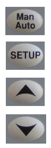
Selects manual or automatic mode. Becomes
« Reset » on UDC1200 Limit model.
Allows operator mode parameters to be scrolled.
In combination with the «Upper» key, allows
configuration mode or Setup mode to be entered.
Increases setpoint, output or configuration
parameter values.
Decreases setpoint, output or configuration
parameter values.
Optional Features
The following can be selected via the Model selection
Guide (see page 8):
RS485 ASCII communication
RS485 Modbus RTU communication
Digital Input
Output 2
Output 3
Power Supply 24/48 Vac/dc
Physical Description
The UDC1200 controller is housed in a 110 mm (4.33
inches) deep case with a standard UDC gray bezel. It
can be mounted in a 1/16 DIN panel cutout.
The UDC1700 controller is housed in a 100 mm (3.94
inches) deep case and can be mounted in a 1/8 DIN
panel cutout. By using the pre-assembled mounting
fixture delivered with the unit, you can easily and
securely install the controller into the panel cutout.
Modular plug-in construction allows rapid access and
saves time. All inputs and outputs are connected on
the rear terminal block by screws.
Operator Interface
Four display combinations are offered to the operator.
The upper 4-digit 7-segment display is always
dedicated to monitor the PV. The lower display can
show:
SETPOINT (read only)
SETPOINT (adjustable)
RAMPING setpoint (ramp mode)
BLANK
Universal Inputs
All input types are available on any unit. Selection
among the various types of inputs is made by prompt
configuration. As soon as the Process Variable
reaches the value of the input range limit, the controller
displays a message. A sensor break indication is also
provided. A configurable digital filter is available from
0.5 seconds to 100.0 seconds.
Outputs
Three types of outputs (RELAY, SSR driver or DC linear)
are selectable for three outputs, through the model selection
guide or by adding a plug-in module for outputs 1, 2 and 3.
Outputs Algorithm
The UDC1200 and UDC1700 are available with the
following output algorithms:
Time proportional:
ON/OFF or time proportional with
electromechanical relay SPDT 2 A or SSR driver
(open collector).
Current proportional:
Supply directly proportional current or voltage
signal to the final control elements which require 0-
20 mA, 4 20 mA, 0-10 V or 0-5 V.
Time proportional duplex:
Three duplex modes can be selected, either
ON/OFF duplex, time proportional duplex
(heat/cool with two proportional bands, two cycle
times and deadband) or TPSC.
Current proportional duplex:
In addition to the first current/voltage output, a
second similar output with its own proportional
band is provided.
Current/Time or Time/Current duplex:
Provides a variation of traditional time or current
duplex mode by mixing current and time
proportioning together.
Control Algorithms
Four control algorithms can be set up through the
configuration menu:
On/Off PID
PD + MR TPSC
The TPSC (Three Position Step Control) control algorithm is
dedicated to control valve positioning without slidewire
feedback from the motor shaft.
Configuration
There are two levels of configuration. The SET-UP
mode allows modification of current parameters such
as tuning parameters, alarm values, setpoint limit,
ramp enable, auto-manual mode enable and autopretune enable.
The CONFIGURATION mode is more oriented to unit
personality: input selection, output 2 and 3 usage,
alarm type, communication address and lockout code.
The operator mode screens are only selectable via the
configuration software only. For instance, the alarm
value screen can be moved from setup mode to
normal operator mode if desired.
Control Mode
Manual or automatic mode with bumpless transfer is
standard feature. In manual mode, the operator can
directly control the output through the two front face
keys (raise and lower keys). The output value is
monitored on the lower display.
Alarms
Outputs 1, 2 and 3 can be used as alarms. Two
electromechanical single pole double throw relays can
activate external equipment when alarm setpoints are
reached. An LED is also activated on the front-face. A
direct or reverse acting alarm output can be
configured. A logical combination of the two alarms:
OR, AND or hysteresis (active when both alarms are
active and inactive when both alarms are inactive) can
be set which associates the two alarms status before
energizing the relay. In order to detect a defective
control loop, the controller can supply special loop
alarm control by continually monitoring the PV
response to output demand. A timer is automatically
set up when any output is on saturation mode. When
the timer reaches twice the reset time with no PV
response, the loop alarm is activated. With this soft
alarm there is no need for a heater circuit breaker,
saving wiring time and costs.
Display
Dual, four-digit LED display with decimal point location
configurable up to three places for linear ranges only.
Limit Controller
The UDC1200 1/16 DIN limit controller provides a latched
relay output which is activated when the process parameters
either exceed or fall bellow the desired value, providing a
failsafe cut-off which has to be manually reset before the
process can continue.
The UDC1200 limit controller can be configured to be either
a “high limit” unit where the delay will de-energize when the
PV is above the limit setpoint, or a “low limit”, where the
relay will drop out when the PV falls below the setpoint.
A LED indicator shows when limits have been exceeded,
and when the relay is latched out.
The optional digital input allows a remote reset function.
Remote Setpoint Model
The UDC1700 1/8 DIN "R" model controller has a second
input available that accepts either a linear or potentiometer
input signal as a remote setpoint. The input signals
accepted are field-configurable and are: 0-5 V, 1-5 V, 0-10
V, 2-10 V, 0-20 mA, 4-20 mA (factory set), 0-50 mV, 10-50
mV, 0 100 mV, or 0-2000 ohms. This allows the controller
to act as a "slave" controller accepting a setpoint value from
a 'master' device such as a PLC or setpoint-programming
controller (such as the DCP50, DCP100, DCP300, or
DCP550 series).
The UDC1700R also includes a standard digital input
allowing remote switching between the local setpoint and
the remote setpoint value. Also standard in this model is
"fuzzy" autotune software that minimizes process variable
overshoot when responding to a setpoint change.
PC Software
The UDC1200 & 1700 are supported with PC software
allowing you to quickly configure your device using
configuration wizards, or to perform diagnostics
Warranty/Remedy
Honeywell warrants goods of its manufacture as being free of defective materials and faulty workmanship. Contact your local
sales office for warranty information. If warranted goods are returned to Honeywell during the period of coverage, Honeywell
will repair or replace without charge those items it finds defective. The foregoing is Buyer's sole remedy and is in lieu of all
other warranties, expressed or implied, including those of merchantability and fitness for a particular purpose.
Specifications may change without notice. The information we supply is believed to be accurate and reliable as of this
printing. However, we assume no responsibility for its use.
While we provide application assistance personally, through our literature and the Honeywell web site, it is up to the
customer to determine the suitability of the product in the application
-
 Beckhoff CX5620-0225 CPU module
-
 Beckhoff CX5620-0220 CPU module
-
Beckhoff CX5620-0215 CPU module, Beckhoff RT Linux®
-
 Beckhoff CX5620-0210 CPU module, Beckhoff RT Linux®
-
 Beckhoff CX5620-0195 CPU module
-
Beckhoff CX5620-0190 CPU module
-
Beckhoff CX5620-0185 CPU module
-
Beckhoff CX5620-0175 CPU module
-
 Beckhoff CX5620-0170 CPU module
-
Beckhoff CX5620-0163 CPU module
-
Beckhoff CX5620-0161 CPU module
-
Beckhoff CX5620-0160 CPU module
-
Beckhoff CX5620-0100 CPU module
-
 Beckhoff CX5120-0195 CPU module
-
 Beckhoff CX5120-0190 CPU module
-
Beckhoff CX5120-0185 CPU module
-
Beckhoff CX5120-0175 CPU module
-
 Beckhoff CX5120-0170 CPU module
-
Beckhoff CX5120-0163 CPU module
-
Beckhoff CX5120-0162 CPU module,
-
Beckhoff CX5120-0161 CPU module
-
Beckhoff CX5120-0150 CPU module
-
Beckhoff CX5120-0143 CPU module
-
Beckhoff CX5120-0142 CPU module
-
Beckhoff CX5120-0141 CPU module
-
Beckhoff CX5120-0140 CPU module
-
Beckhoff CX5120-0130 CPU module
-
Beckhoff CX5120-0123 CPU module
-
 Beckhoff CX5120-0122 CPU module
-
Beckhoff CX5120-0120 CPU module, Microsoft Windows Embedded Standard 7 P
-
 Beckhoff CX5120-0113 CPU module
-
Beckhoff CX5120-0112 CPU module
-
Beckhoff CX5120-0111 CPU module
-
 Beckhoff CX5120-0110 CPU module, Microsoft Windows Embedded Compact 7
-
Beckhoff CX5120-0100 CPU module, no operating system
-
Beckhoff C6017-0040 | Fanless ultra-compact Industrial PC
-
Beckhoff C6017 | Fanless ultra-compact Industrial PC
-
 Beckhoff C6015-0030 | Fanless ultra-compact Industrial PC
-
Beckhoff C6015-0040 | Fanless ultra-compact Industrial PC
-
Beckhoff C6015 | Fanless ultra-compact Industrial PC
-
Beckhoff C6015 | Fanless ultra-compact Industrial PC
-
 Beckhoff CX2500-M510 | Fieldbus master module
-
 Beckhoff CX2500-M310 | Fieldbus master module
-
 Beckhoff CX2500-B510 | Fieldbus slave module
-
 Beckhoff CX2500-B310 | Fieldbus slave module PROFIBUS for CX20xx, CX52x0. CX53x0. CX56x0
-
 Beckhoff CX2500-0070 | USB 3.0 module for CX20xx, CX52xx, CX53x0. CX56x0
-
 Beckhoff CX2500-0062 | 2.5 Gbit Ethernet module for CX20xx, CX52x0. CX53x0. CX56x0
-
 Beckhoff CX2500-1061 | Power over Ethernet module for CX20xx, CX52x0. CX53x0. CX56x0
-
 Beckhoff CX2500-1060 | Ethernet module for CX20xx, CX52x0. CX53x0. CX56x0
-
 Beckhoff CX2500-0031 | Serial Interface RS485/RS422 for CX20xx, CX52x0. CX53x0. CX56x0
-
 Beckhoff CX2500-0030 | Serial Interface RS232 for CX20xx, CX52x0. CX53x0. CX56x0
-
 Beckhoff CX5230-0195 CPU module
-
Beckhoff CX5230-0190 CPU module
-
Beckhoff CX5230-0175 CPU module,
-
Beckhoff CX5230-0170 CPU module
-
Beckhoff CX5230-0100 CPU module, no operating system, no TwinCAT
-
 Beckhoff CU8130-0240 | UPS modul, battery-backed
-
 Beckhoff CU8130-0120 | UPS module, battery-backed
-
 Beckhoff CU8110-0120 | UPS module, capacitive
-
 Beckhoff CU8110-0060 | UPS module, capacitive
-
 Beckhoff CX5130-0195 CPU module
-
 Beckhoff CX5130-0190 CPU module
-
Beckhoff CX5130-0185 CPU module
-
Beckhoff CX5130-0170 CPU module, Microsoft Windows 10 IoT Enterprise 2019 LTSC
-
Beckhoff CX5130-0163 CPU module
-
Beckhoff CX5130-0162 CPU module
-
 Beckhoff CX5130-0161 CPU module
-
Beckhoff CX5130-0160 CPU module
-
Beckhoff CX5130-0155 CPU module
-
Beckhoff CX5130-0150 CPU module
-
Beckhoff CX5130-0143 CPU module
-
Beckhoff CX5130-0142 CPU module
-
Beckhoff CX5130-0140 CPU module
-
Beckhoff CX5130-0135 CPU module
-
Beckhoff CX5130-0130 CPU module
-
Beckhoff CX5130-0125 CPU module
-
 Beckhoff CX5130-0123 CPU module
-
Beckhoff CX5130-0122 CPU module
-
Beckhoff CX5130-0121 CPU module
-
 Beckhoff CX5130-0115 CPU module
-
Beckhoff CX5130-0113 CPU module
-
Beckhoff CX5130-0112 CPU module
-
Beckhoff CX5130-0111 CPU module
-
Beckhoff CX5130-0110 CPU module, Microsoft Windows Embedded Compact 7. no TwinCAT
-
Beckhoff CX5130-0100 CPU module, no operating system, no TwinCAT
-
 DEIF FAS-113DG Synchronisation & circuit breaker closing
-
 DEIF FAS-115DG Synchronisation & circuit breaker closing
-
 DEIF HAS-111DG Synchronisation & circuit breaker closing
-
 DEIF LSU-122DG Load sharing, paralleling & operation
-
 DEIF LSU-114DG Load sharing, paralleling & operation
-
 DEIF LSU-113DG Load sharing, paralleling & operation
-
 DEIF LSU-112DG Load sharing, paralleling & operation
-
 DEIF RMF-112D Frequency relay
-
 DEIF RMC-142D Current relay
-
 DEIF RMC-132D Current relay
-
 DEIF RMC-131D Current relay
-
 DEIF RMC-122D Current relay
-
 DEIF RMC-121D Current relay
-
 DEIF RMC-111D Current relay
-
 DEIF MVR-V211 Busbar Protection
-
 DEIF MVR-T257 Transformer Differential Protection
-
 DEIF MVR-T256 Transformer Differential Protection
-
 DEIF MVR-T216 Transformer Differential Protection
-
DEIF MVR-T215 Transformer Protection
-
 DEIF MVR-M257 Motor Differential Protection
-
 DEIF MVR-M255 Motor Protection
-
 DEIF MVR-M215 Motor Protection
-
 DEIF MVR-M210 Motor Protection
-
 DEIF MVR-G257 Generator Differential Protection
-
 DEIF MVR-G215 Generator Protection
-
 DEIF MVR-F255 Directional Feeder Protection
-
 DEIF MVR-F215 Directional Feeder Protection
-
DEIF MVR-F210 Feeder Protection
-
 DEIF MVR-F205 Directional Feeder Protection
-
 DEIF MVR-F201 Basic Feeder Protection
-
DEIF MVR-200 series Medium Voltage Relay
-
 DEIF MDR-2 Multi-differential relay
-
 DEIF LMR-122D Loss of mains relay
-
 DEIF LMR-111D Loss of mains relay
-
 DEIF APU-4 Advanced G59 and G99 protection unit
-
 DEIF iE 650 PLC - The most robust programmable automation controller available
-
 DEIF iE 350 PLC - Programmable Automation PLC Controller
-
 DEIF iE 250 PLC Versatile and modular intelligent energy PLC controller
-
 DEIF PPM-3 EDG Protection and Power Management
-
 DEIF AGC 3X 4198000234E AUTOMATIC GENSET CONTROLLER
-
 SAUTER ASF123 Damper actuator with spring return
-
SAUTER ASF122 Damper actuator with spring return
-
SAUTER ASF113F122 Damper actuator with spring return