
HoneywellControlEdge HC900 Controller Specifications 51-52-03-31, January 2022
Overview
The Honeywell ControlEdge HC900 Controller is an
advanced loop and logic controller offering a modular
design sized to satisfy the control and data management
needs of a wide range of process equipment. When
combined with the optional 900 Control Station operator
Interface that is highly integrated with the controller’s
database, configuration and setup time is minimized. This
powerful combination together with Honeywell’s
performance proven control technology provides users an
ideal solution for process control. Open Ethernet
connectivity with Modbus TCP Protocol also allows network
access using a variety of HMI/SCADA software. Program
execution environment is protected using an independent
watchdog timer.
Easy-to-use Windows-based Designer software, operable
over Ethernet or RS485 port (isolated) simplifies controller
configuration. The software is available in English, Chinese,
Russian, and German language version. It provides
advanced monitoring functions for debug, allows run-mode
process configuration changes while maintaining process
control, uploads the complete, annotated graphic controller
configuration, plus supplies an array of reports for
enhanced documentation. The ControlEdge HC900
Controller provides superior PID loop control and more
robust analog processing than most logic controllers without
compromising logic performance. A separate, fast scan
cycle executes a rich assortment of logic and calculation
function blocks. Logic blocks may also execute in the same
scan with analog function blocks for time critical events.
These function blocks may be fully integrated into a
combined analog and logic control strategy for
uncompromising control performance.
For more information see specification sheets:
• ControlEdge 900 Platform Modules
Specs 51-52-03-41
• Designer Software Specs 51-52-03-43
Applications
Mining & Metals Furnaces, Kilns, Boilers
Chemicals, Extruders Autoclaves
Pharmaceuticals Sterilizers, Dryers
Rail/ Infrastructure Burner Management,
HVAC/ DataCenters Combustion Control
Pulp & Paper Emergency Shutdown
Cement & Glass Pipeline Monitoring,
Power Spill Prevention
Features Summary
• Supports Split Rack Redundancy
• Supports Honeywell FDM (Field Device Manager)
using HART IP
• Supports HART function blocks (Command 3 and 48)
Note: UIO Module is required for HART support
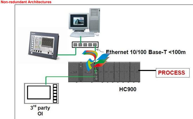
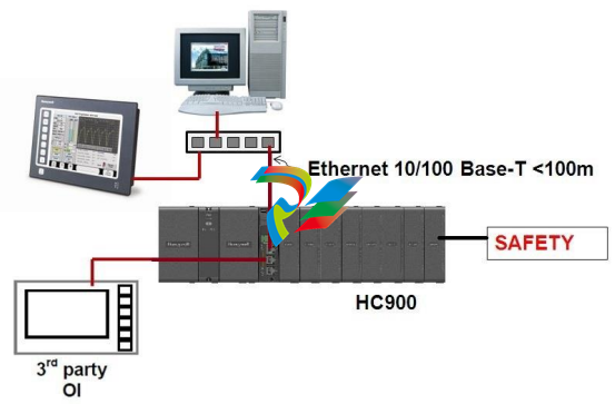
• Non-redundant and Redundant Architectures
• Sequence of events support (SOE)
Note: Supported only in non-redundant UIO
configuration.
• Redundant and Non-redundant Safety Universal IO
• PID Control with advanced Accutune III auto-tuning
• Safety peer communication between ControlEdge
HC900 controllers
• External watchdog timer with independent clocks
that detect spurious CPU lockups
• Adjustable recipe pool memory lets you allocate
memory for recipes, SP Profiles, sequences and
schedules to meet your needs
• Up to 4608 points with remote I/O
• Boolean Logic programming. Robust assortment of
over 100 algorithms
Features Summary, continued ..
• Advanced Floating Point Math Functions.
• Extensive alarm and event monitoring
• Up to 2304 galvanically Isolated, Analog Inputs
• Up to 1008 redundant UIO points
• New I/O voting and output validation function
blocks.
• Remote I/O Racks with wire for extended
distance.
• Star or Ring topology on IO network using
recommended switches
• Scanner and I/O Insert/Remove under power
• LED on/off indicators on digital I/O
• Graphic Function Block Configuration
• Open 10MB or 10/100MB Ethernet interface using
Modbus/TCP. Peer-to-peer communications via
Ethernet
• E-mail alarm/event messaging on priority
• Ramp/Soak Setpoint Programmers
• Setpoint Schedulers with multiple outputs
• Sequencers with 16 Outputs each
• Modbus read/write parameters assignable to either
fixed or custom addresses for access by HMI or
supervisory software.
• Modbus TCP Initiator
• Gas flow function blocks per American Gas
Association specs. (non-Safety configurations
only).
• Calendar block for triggering events
• Non-interfering process/safety worksheets capable
of handling process and safety configurations.
• Built in Version Control
• Fast updates - 10 ms digital and UIO (900U02-
xxxx) 100ms analog capable
Note: Low Level AI updates @ 0.5 sec.
ControlEdge HC900 Controller
• The rack based ControlEdge HC900 Controller is
available in 4 rack sizes with 1, 4, 8 or 12 I/O slots
each to support a wide range of requirements.
• Redundant C75 controllers use a separate controller
rack for CPUs without local I/O. Two power supplies
provide separate CPU power.
A redundant controller switch module provides status
and performs mode changes.
CPU Modules
• The CPU options available for the ControlEdge
HC900 Controller include:
▪ C30 and C50 for non-redundant applications.
▪ C70 for dual networking.
▪ C75 for redundant CPU applications and dual
networking.
▪ All ControlEdge HC900 CPU modules are based on the
e300 32 Bit RISC based PowerPC Architecture. The
controller operates out of a battery-backed DDR2 64MB
memory for C30 and C50 modules, 128MB for C70 and
C75 modules. DDR2 memory on all modules is
supported with ECC circuitry to enhance reliability and
error detection.
Program execution environment is protected using an
independent watchdog timer.
• All ControlEdge HC900 CPU modules offer open Ethernet
communications for access by a variety of HMI and
SCADA software applications and peer to peer
communications for control data exchanges between
controllers. The C70 and C75 provide dual Ethernet ports
for high network availability installations.
• ControlEdge HC900 CPU modules use a dual scan
method to handle fast digital scanning and normal analog
input scanning in the same integrated control
environment. Both scans support a wide range of
computational function block algorithms and a user
adjustable execution sequence order.
ControlEdge HC900 CPUs use Flash memory for
permanent user configuration program storage
and battery-backed memory for dynamic data
storage allowing for graceful recovery following a
power interruption or other discontinuous
operations. Using proven TL5903 primary
batteries to support up to 24 days of continuous
power outages
• 5000 SOE event buffering capability
I/O Scanners
ControlEdge HC900 Remote I/O is processed and
communicated to the main CPU module through a
remote I/O Scanner module. Two I/O scanner modules
are available: a single port model for non-redundant
CPU systems and a dual port model for redundant
CPU systems. Scanner addressing in multi-rack
systems is selectable via DIP switch setting.
Program execution environment is protected using an
independent watchdog timer.
Inputs and Outputs - A variety of I/O modules are
available for selection in creating a custom control
solution. These include:
• 8-point universal analog input modules: Inputs
may be mixed on a module and may include
multiple thermocouple types, RTDs, ohms,
voltage, current or millivoltage types – all easily
assigned using the Designer configuration tool.
High point-to-point isolation simplifies installation
and saves the expense of external isolation
hardware.
• 16-point high level analog input module: each
point is configurable for V or mA. Point-to-point
isolation.
• 4-point galvanically isolated analog output
module: Supports from 0 to 20mA each.
• 8-point analog output module. Galvanically
isolated in two groups of 4. Supports 0 to 20mA.
• 16-point (14-point for redundant configuration)
Universal I/O module galvanically isolated Input/
Output to chassis. Each point can configured as
DI, DO, AI or AO.
• 16-point digital galvanically isolated AC/DC input
module.
• 16-point analog output module. Galvanically isolated in
four groups of 4. Supports 0 to 20mA.
• 16-point digital galvanically isolated input modules:
Contact closure type, DC voltage and AC voltage types.
• 32-point galvanically isolated digital input (sink) module:
DC voltage
• 8-point AC or 16 point galvanically isolated DC digital
output (sink) modules
• 32-point galvanically isolated digital output (source): DC
voltage
• 8-point galvanically isolated high voltage
• 8-point galvanically isolated relay output module: four
form C type and four forms A type relays.
• 4 channel Pulse/ Frequency/Quadrature I/O module
See Module Specifucation sheet 51-52-03-41 for details.
Insert & removal of I/O under power - For ease of
maintenance, the ControlEdge HC900 controller supports
removing and inserting modules from the card rack without
removing power from the controller. Each card is sensed for
validity by the controller and auto-configured on insertion.
Hardware can be replaced without shutting down operations
for replacement of CPU or Scanner modules thus reducing
downtime and total cost of ownership.
I/O Terminal Blocks – 20-screw Terminal Blocks
are available with either barrier style or Euro style screw
connections. A module label area is provided for field wiring
identification. An available 36-screw Euro Terminal block is
required for certain high capacity modules.
Remote I/O - I/O racks may be remotely mounted
from the controller via a dedicated Ethernet 10/100Base-T
connection at up to 300 meters (984 feet) between the
controller and the most remote rack using two Ethernet
switches. Use of fiber optic cable extends distance to 40
Kilometers.
Remote Terminal Panels - Optional DIN rail mounted
Remote Terminal Panels (RTPs) are available for use
with pre-wired cables to reduce installation time and
labor expense. RTP types available: analog input,
relay output, discrete input, discrete output, analog
output.
Three cable lengths are also available to match
hardware to installation variations. See Module
Specification sheet 51-52-03-41 for more details.
Redundant Power - A second (backup) power module may
be added to each ControlEdge HC900 controller rack. An
extended rack is available that expands the standard 8 and
12 I/O rack to accommodate a second (redundant) power
supply and power status module.
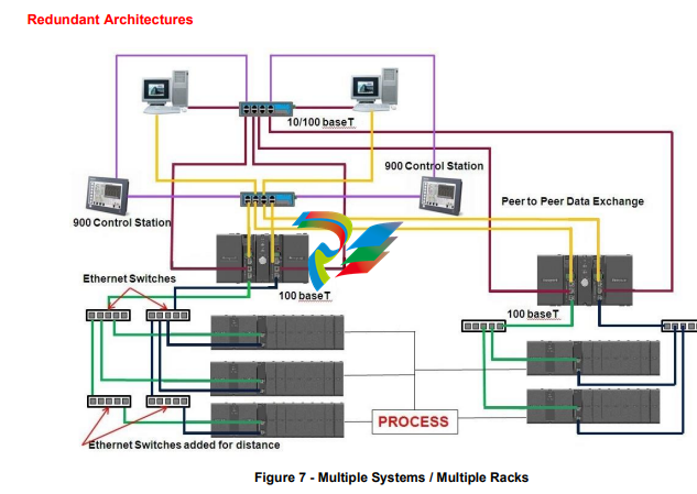
Redundant Architectures
Redundant Controller
Two redundant C75 CPUs operate in a separately
mounted controller rack, each with an independent
900PS1 model power supply. A Redundant Switch
Module (RSM) is located in the rack between the two
C75 CPUs. A key switch on the RSM allows the user
to change the operating mode of the Lead CPU. There
is no I/O in the controller rack; the CPUs communicate
with up to 12 racks of I/O over a 100 base-T Ethernet
physical communication link or fiber optics with an
external media converter for greater distance. When
more than one I/O rack is used in the system, Ethernet
switches are required, one port for each Scanner
connection. In operation, all control functions and host
communication exchanges are handled by the Lead
controller, including configuration and operator
changes. The Lead controller updates the Reserve
controller every scan cycle with all the information
needed to assume control in the event of a fault
condition.
After power-up of the C75 CPUs, the first available
CPU assumes the Lead function. The Lead may be
transferred to the Reserve controller by:
• Failure of the Lead controller,
• Manually changing a keyed switch located on
the Redundant Switch Module,
• Input pin on Redundancy Status function block, or
• Instruction from host communication.
Dual Networks for Host communications are provided on the
C75 CPU. Both network ports are continuously active on the
Lead controller. Matrikon OPC server is available from
Honeywell Matrikon to support dual Ethernet
communications and automatically transfer communications.
The C75 network ports may otherwise be used in nonredundant mode where only one of the communication ports
is used.
Remote I/O - To extend the distance between the CPU rack
and the most distant I/O rack to 300m (984 ft.) up to two
Ethernet switches may be used in each I/O connection.
Distances up to 40km are possible with fiber optic cable.
Operator Interface – The 900 Control Station Operator
Interfaces (900CR series) is supported with the C75 CPU.
An Ethernet connection is made to a switch connected to
the Ethernet port of each CPU. The operator interface
communication to the controller follows the Lead controller
assignment.
Status/Diagnostics - An output parameter of the system
monitor function block of C75 CPUs provides a digital status
of the Reserve controller to allow integration of this
information into the control strategy. C75 CPUs also provide
diagnostic status on redundancy operation that may be
observed using Designer configuration software. A
Redundancy status function block is also available to
monitor redundant controller operation.
Function Blocks
A large assortment of analog and digital function
blocks are available to solve the most demanding
control requirements. Function blocks are grouped by
scan rate, fast or normal, and by function, Principal or
Standard.
Function Block Execution - All function blocks
operate synchronously with I/O processing. Inputs are
measured at the start of every scan and outputs are
updated at the end of every scan. Function blocks
such as Time Proportioning Outputs (TPO) and
Position Proportioning outputs (PPO) require higher
output resolution and are updated when the function
blocks are executing. Micro-controllers on digital I/O
modules can maintain TPO duty cycle operation during
failsafe conditions. Micro-controllers on all I/O modules
allow outputs to be configured to assume a default
state in the event of a fault condition.
Normal Scan: Function blocks that execute during the
Normal Scan are synchronized to the analog input
measurements. The fastest update rate is 500ms.
100ms analog capable from version v6.300 and above.
Note: Low Level AI updates @ 0.5 sec.
Fast Scan: The fastest update rate for fast scan
function blocks in a single controller rack is 10ms. The
update rate starts at 25ms when remote racks are
used and for redundant systems.
Principal Function Blocks – These function blocks
are supported by dedicated Widget objects in Station
Designer software for configuring 900 Control Station
operator interfaces. They have Tag names and other
attributes to support on-line user interaction. Principal
function blocks can be used any number of times in a
configuration.
Typical Principal function blocks include PID, Set Point
Programming, Sequencers, Alternators, Stage, etc
Standard Function Blocks – The number of standard
function blocks that may be used in a configuration is
virtually unlimited. Typical Standard blocks include
totalizer, free-form math, average, mass flow, function
generator, periodic timers based on real-time, carbon
potential, RH, Dew Point, signal selection, comparison,
gas flow, real time clock, and many others. These
blocks may be configured to create control schemes
that precisely address the needs of your process.
Digital status outputs are also provided on many of the
analog function blocks to facilitate intelligent signal
alarming and default operation strategies.
Typical logic function blocks include AND, OR, XOR, NOT,
Latch, Flip-flop, On/Off Delay and Resettable timers,
Counters, Free-form Boolean logic and more. The execution
of analog and digital functions is seamlessly integrated into
a single control strategy in the controller.
AI-V – The new AI-V function blocks will allow 1oo2 and
2oo3 voting for inputs and compares its values with one
another and reports any deviation if validation between one
another fails. Output value is calculated by comparing all
inputs channels and selecting best of three.
DI-V - The new DI-V function blocks will allow 1oo2 and
2oo3 voting for inputs voting for inputs and compares its
values with one another and reports any deviation if
validation between one another fails. Output value is
calculated by comparing all inputs channels and selecting
best of three.
AO-V – The AO-V block is similar to the AO block but it
provides additional functionality which allows users to
validate the status of the output using a feedback input
channel. The primary function of this block is to validate the
feedback signal and provides indication when input fails to
match the output due to possible reasons such as field
power failure, cable failure, fuse etc. The function block will
also check the feedback input signal for input module error,
failed input channel and loss of feedback module
communications.
DO-V - The DO-V block is similar to the DO block but it
provides additional functionality which allows users to
validate the status of the output using a feedback input
channel. The primary function of this block is to validate the
feedback signal and provides indication when input fails to
match the output due to possible reasons such as field
power failure, cable failure, fuse etc. The function block will
also check the feedback input signal for input module error,
failed input channel and loss of feedback module
communications.
Alarms/Events
Alarms and events represent changes in digital status that
require user notification. The ControlEdge HC900 controller
supports an internal alarm annunciation system that may be
setup to operate via e-mail to a remote computer (see
Communications, E-mail Alarming). Up to 360 alarm points
per controller may be grouped in 30 groups of 12.
Events are digital status changes that cause messages to
be presented on the 900 Control Station operator interface.
Controller events may prompt e-mail messages,
do not require acknowledgement, and are reported and
logged in a separate group. Up to 64 event points are
supported in a controller.
Alarms and events are time stamped in the controller to a
one second resolution.
Sequence of Event (SOE)
SOE is a mechanism for recording and determining the
order (sequence) of digital state changes (on DI
channel). High-resolution SOE uses 1 msec time
stamping. SOE display tool (historian or control station)
shall map the SOE event properties from signal
number in configuration file.
Note:
• SOE is supported only in non-redundant UIO
configuration.
• As of now SOE events across controllers may not be
correlated properly as there is no time sync across
controllers
Configuration
Controller configuration is performed using Designer
Configuration software on a PC operating with
Windows™ 7 (32-bit and 64-bit), Windows™ 8.1 (32-bit
and 64-bit), Windows™ 10 (32-bit and 64-bit), Windows
Server 2016, and Windows Server 2019. Configuration
files are built independently on the PC and downloaded to
the controller in a separate operation.
Validation of proper physical I/O to support the
configuration is provided along with appropriate warnings.
Configuration Back-build - In the event a PC
configuration file is lost or misplaced, it can be easily
reconstructed using the upload function of the Designer
configuration software. Simply read the configuration
from the controller to exactly duplicate the original
configuration, including all text descriptions.
Configuration edit - In the event edits to a controller’s
configuration are required after the unit is in operation, an
uploaded file may be monitored during process operation,
edited, and downloaded with the on-line download function
of the Designer. The software allows configuration changes
while in the Run mode, limiting process disturbances.
Note: Forcing and downloads cannot be made on Safety
controllers unless they are switched to the RUN/PROGRAM mode.
I/O Redundancy
CAUTION: For I/O redundancy, prefabricated cable length
from RTP to Redundant UIO modules must be same.
• Flexibility in configuration
• I/O Redundancy RTP (Model No – 900RTI-0100)
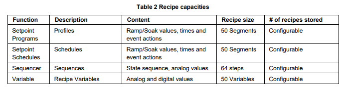
Recipes
Recipes are groups of data defined by the user that are
used to make multiple value changes in the controller
through a single action. Function block types that accept
recipe data and the quantity of recipes stored in the
controller are listed in Table 2.
Recipes may also include Variables, which are dynamic
analog and digital values used as inputs to standard and
principal function blocks. Recipes may be loaded through
the 900 Control Station operator interface by name or
number, or via a dedicated recipe load function block and
user configured logic.
Operator Interfaces
A ControlEdge HC900 controller can support up to three
900 Control Station operator interfaces via Ethernet or
Serial communications. The interface is configured with
Station Designer software using a database
import function to simplify the setup. See specification
sheet 51-52-03-102 for more information on this
interface.
Note: The old phased-out Control Stations (900CS10-
00/ 900CS15-00) will not support import of HC900
software configuration file (*.cde) v7.1 and above. For
HC Designer v7.1 and above please migrate to new
900CR series Control Stations with Station Designer
v3.1.7100 and above.
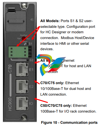
Communications
HART IP – The HC900 controller supports industry
standard HART (Highway Addressable Remote
Transducer) protocol to integrate with asset manager
(Currently it is qualified with Honeywell FDM).
HART supports two functionalities:
• HART IP client (FDM) communication
• HART Function Block communication
The controller enables the HART IP client to exchange
information with HART field devices connected to the
Al/AO channels in the controller via a HART-IP Server.
Multiple HART IP clients can be served by the
controller at the same time. When the HART IP client
builds a HART command request and sends it to the
TCP/IP port of the HART-IP server, the HART-IP
server responds to the HART IP client with information
from the field device. Since it takes time for the
controller to communicate with the field devices
through onboard or remote I/O cards, a delayed
response mechanism is implemented. The TCP /IP
port of the HART-IP server is user-configurable and
the default port number is 5094. The end user may
change the port number if firewall configuration is
required.
The controller enables HART function blocks to access
to the HART field devices through HART-enabled
Al/AO channels. Currently HART command 3,
command 48 and command X are implemented.
Remote I/O Rack Port (C50, C70, C75) – An Ethernet
port is dedicated to supporting remote I/O racks. This
10/100Base-T Connection on the C50 and C70 CPU
supports a single direct connected remote rack or up
to 11 remote racks when connected through an
external Ethernet switch. The C75 CPU supports a
single direct connected rack or up to 12 remote racks
using external switches.
User Interface Support – The 900 Control Station interface
may be connected via Ethernet or serial communications. Up
to three interfaces may be connected to a controller for
distances up to 328 feet (100Meters) via Ethernet or 2000
feet (609 meters) between the controller and operator
interface. 3rd party user Interface support is provided through
an isolated RS485 port connection using Modbus/RTU
protocol, or Ethernet with Modbus/TCP protocol.
Ethernet Modbus/TCP Communications –
ControlEdge HC900 controllers communicate with their host
PC interfaces over an Ethernet 10/100Base-T communication
network using the Modbus/TCP protocol, an open protocol
interface available for most popular HMI software packages.
The controllers Ethernet ports are MDIX and configured to
auto negotiate and will default to half duplex if host fails to
negotiate. The C30 supports up to 5 host connections while
the C50/C70/C75 support up to 10 concurrent host
connections over an Ethernet network for control supervision
and data acquisition. The Designer software can also address
any of the controllers concurrently over Ethernet for
configuration monitoring, diagnostic interrogation, upload/
download, or on-line configuration changes. As a result, a
ControlEdge HC900 network of controllers and operator
interfaces can be partitioned into process segments to assure
proper control performance. Each of these process segments,
in turn, can be accessed via common HMI software within the
plant environment using an Ethernet LAN.
Ethernet Peer to Peer Communications - Peer data
communications between one ControlEdge HC900 controller
and up to 32 other ControlEdge HC900 controllers is
supported over Ethernet via UDP protocol for safety/process
data sharing. Both digital and analog data exchange are
supported using peer data exchange function blocks, up to
2240 (max 44 peer writes per modbus device) parameters
between peer controllers. For SIL variants the safety peer
function blocks can be used for Safety peer communication
along with peer data exchange function blocks. No
specialized software is required. Peer data can be given
signal tag references for use in a control or data acquisition
strategy. Peer to peer data interchange does not consume
one of the host connections.
Serial Modbus RTU Communications - Serial Modbus
RTU communications is available on the isolated RS485 (2
wire) ports of the ControlEdge HC900 Controller CPU
assembly in a Modbus Host or Device mode. The protocol of
these ports is user selectable between ELN protocol for use
with HC Designer software or Serial Modbus to interface
with other compatible devices.
Modbus RTU Device - Isolated RS485 ports
may be configured for simultaneous operation as a
Modbus device port to allow each to communicate with
a single Modbus host.
The Modbus protocol supports read and write access
to a default address map of certain function blocks and
parameters.
In configurations 4.0 and later, a map of customized
addresses, blocks and parameters can be created
either by editing the default map or from scratch.
In the default map (fixed), a 4000 register array is
available to allow the user to specify the address
locations of specific controller data to optimize
controller communications.
The data in the array may also be accessed in user
specified formats (data types) such as analog data in
Float 32, unsigned 16, signed 16, unsigned 32, signed
32, and digital data in signed 16 or unsigned 16.
The data type selections in the 4000 register array
provide compatibility with devices such as 3rd party
touch panels. In the custom map, all data formats are
adjustable.
Modbus RTU Host - Either of the ports may be
configured as a Modbus RTU host, one per controller.
Up to 32 devices may be multi-dropped on the isolated
RS485 port. Function blocks are available in the
ControlEdge HC900 controller to allow the user to
specify read and write operations to up to 32 external
Modbus compatible modus device devices and up to
1024 data points.
Modbus TCP Initiator – The Ethernet ports may be
configured as a Modbus TCP initiator. Function blocks
are available in the ControlEdge HC900 controller to
allow the user to specify read and write operations to
compatible modbus device devices for up to 1024 data
points.
Profibus – The ControlEdge HC900 can access data from
Profibus modbus device devices using a Modbus-toProfibus gateway device attached to the serial port of the
controller. The gateway device is a Profibus Host on the
fieldbus network and a Modbus device to the ControlEdge
HC900. The Profibus data is connected into the control
strategy using Modbus function blocks. This application has
been validated with a ProLinx 5104-MCM-PDPM gateway
(from ProSoft® Technology).
E-mail Alarms/Events--ControlEdge HC900 alarms or
events can be individually configured to send an e-mail
alarm (or event) message to e-mail addresses with the
assigned alarm priority.
• Number of e-mail addresses: 3 based on alarm
priority
• From: Controller name (up to 16 characters)
• Subject: text (up to 32 characters)
• Content: date and time of alarm/event, alarm/event
tag name, alarm/event state
• Message: 48 character text (for alarms only)
• Priority Levels: 4 for alarms, 1 for events
Controller Configuration Access –Designer software
supports communicating with ControlEdge HC900
controllers using an Ethernet or serial connection using ELN
protocol to support direct PC connection for configuration
upload, download, debug and maintenance. Modbus RTU
protocol is also supported through the serial port interface.
Once the ControlEdge HC900 controller has been
configured using Designer Software, on-line configuration
changes
may be made while maintaining process control.
Configurations may also be loaded into the controller via the
Ethernet TCP/IP network from a host PC. On-line monitoring
for program debug and on-line program edit functions are
also supported via the Ethernet port.
Modem Access – Communications to the
ControlEdge HC900 controller may be via an external
modem connected to the controller’s using an
RS485/RS232 converter. HC Designer software
supports configuration upload, download and on-line
edits via modem. When modem communication is
selected, Modbus RTU communication timeouts are
extended.
Experion Supervisory Software – Honeywell’s
Windows 10 version is available when PC-based
supervisory control and data acquisition is required.
Ethernet network interface to an Experion server is via
the controller host Ethernet 100 Base-T port using
Modbus/TCP protocol. Client Stations over Ethernet
allow multiple user access to a ControlEdge HC900
network. Using the large selection of standard
operating display templates in Experion saves
development time. When further customization is
needed, the full graphic display development
environment of Experion may be used to fully animate
your process supervisory displays.
A batch reporting option is offered in Release 500 and
430 which enables batch reports to be created using a
standard template. User-entered lot data is supported
and up to 50 parameters can be defined for batch
logging. The file can be exported in .csv format using a
lot number-encoded filename.
SpecView32 Supervisory Software – SpecView32
software can be used as a supervisory interface for
thermal-based applications, offering historical trending,
batch reporting, recipe development involving setpoint
programs and simplified graphics configuration.
ControlEdge HC900 parameters are simply selected
from categorized lists for placement on userconfigured displays or onto display objects.
Network connection is via the controller host Ethernet
10/100Base-T port using Modbus/TCP protocol. A
variety of Windows operating environments are
supported.
OPC Server – Network communication access to
ControlEdge HC900 controllers through third party PC
interfaces is simplified with Honeywell’s Matrikon OPC
server software program. This software supports the
Modbus/TCP interface to either redundant or non-redundant
ControlEdge HC900 controllers. In redundant applications,
Matrikon OPC Server software supports dual Ethernet
connections to both C75 CPUs. Communications to the
controller is maintained during a single network failure
and/or following the transfer of the Lead function from one
CPU to another. Compatible OPC client programs can use
the Ethernet connection to the ControlEdge HC900 via
Honeywell’s OPC Server for remote supervision, data
collection or other supervisory functions.
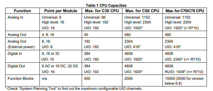
Capacity
The capacity of the ControlEdge HC900 system is
determined by the type of CPU selected, the quantity
of I/O racks, the quantity’s type of I/O modules, the
update rate (scan rate) required, and CPU memory. In
most applications, the CPU memory limit has a low
probability of limiting capacity.
How many I/O channels?
Number of I/O is limited only by physical space.
Namely, the number of racks, the number of modules
per rack, and the number of channels in the modules.
In general,
Maximum I/O channels = (max. number of I/O racks) x
(max. number of modules in each rack) x
(max. number of channels per module)
Examples
Maximum C30 I/O = 1 rack x 12 modules x 32
channels per module = 384 I/O channels
Maximum C50, C70, C75 I/O = 12 racks x 12 modules
per rack x 32 channels per module = 4608 I/O channels.
Maximum C75 Redundant UIO = 6 Redundant racks
(12 racks) x 12 modules per rack x 14 channels per
module = 1008 I/O channels.
How many function blocks (loops, programmers,
etc.)?
Fixed limits are not imposed on function block types.
Your configuration can probably contain as many of
each function block as needed. The limit is reached
when either
a) Dynamic memory is full or
b) Maximum function block quantity is reached or
c) Configuration memory is full or
d) Over 65,535 block configuration parameters or
block inputs used (but not Block Outputs).
These limits are explained below.
a) Dynamic Memory
The rule of thumb is: Max. number of function blocks =
Dynamic memory ÷ memory per function block
The smaller the function block, the more of them can fit
in your configuration.
b) Quantity
Memory limitation is not for function blocks.
Complex blocks such as PID, Programmer, and
Scheduler Sequencer use more memory than simpler
blocks like On/Off, Device Control, Auto/Manual Bias.
For example, several thousand Auto/Manual Bias
blocks would fit in the C30’s memory if not for the quantity
limit of 400.
Conversely, about 300 Scheduler blocks will consume all
the C30’s memory despite the higher quantity limit of 400.
Scan Time Consideration
Another consideration when configuring function blocks is
scan time and the potential for CPU scan time to become
insufficient for the application.
The scan time of a controller increases in fixed increments.
As function blocks are added to a configuration, the time
needed to execute the total configuration is recalculated. If
additional time is needed, the scan time will be increased to
the next increment in sequence. (See Specification section
for scan time increments)
How many recipes in my pool?
Unlike with function blocks, there is no quantity limit to
recipes. The only limiting factor to recipe pool size is
available memory. Whatever memory is unused by the rest
of your configuration (that is, function blocks) can be
allocated for recipes. As long as memory is available,
allocate as many recipes as needed.
The rule of thumb is
Max. number of recipes = Recipe memory allocation ÷
memory per recipe
Configuration memory allocation
The configuration memory comprises one allocation for the
function block configuration and one allocation for recipes.
In general,
Total configuration memory =
Configuration + Recipe allocation
Whatever memory has not been allocated to recipes is
available for your configuration. By changing the size of the
recipe pool allocation, you control the amount of memory
available for recipes and therefore configuration. Need a
small configuration but many recipes? Allocate more recipe
space. Need a large configuration but few recipes?
Allocate less recipe space
Where are usage/capacities presented?
File Properties in Designer displays statistics on
usage/availability of:
• configuration memory (recipes + function
block configuration),
• dynamic memory (function block configuration
only)
• fast scan time,
• Normal scan time,
• Normal CPU% used,
• Fast CPU% used,
• Each component of a configuration (variables,
constants, etc.).
Controller Data Storage
The controller may log process data values in the available
memory that is not used by the configuration. Up to 250
signal values may be logged in a rotating buffer using three
different sample rates with oldest data being replaced with
new data after the buffer is full.
Data is extracted from the controller using HC Historian data
harvesting software via Ethernet or Serial connection.
-
 HIRSCHMANN MSM20-M2M2M2M2SY9HH9E Ethernet media modul
 -
 HIRSCHMANN SPIDER-PL-20-05T1999999TWVHHHH Industrial Ethernet Rail Switch
 -
 Hirschmann SPIDER-PL-20-07T1M2M299TWVHHHH Industrial ETHERNET Rail Switch
 -
.png) Hirschmann (Belden) RS20-1600M2M2SDAEHC09.1.00 DIN-rail managed industrial Fast Ethernet switch
Hirschmann (Belden) RS20-1600M2M2SDAEHC09.1.00 DIN-rail managed industrial Fast Ethernet switch -
 Hirschmann (Belden) RS30-1602O6O6TDAPHC09.1.00 DIN-rail managed industrial Ethernet switch
 -
 Hirschmann (Belden) RS30-2402O6T1SDAPHH09.0.13 DIN-rail industrial Ethernet switch
 -
Hirschmann (Belden) SPIDER-PL-20-04T1S29999TY9HHHH Ethernet DIN-rail switch
-
 HIRSCHMANN RS20-1600T1T1SDAUHX Switch
 -
 HIRSCHMANN BRS42-0012OOOO-SPCZ99HHSES industrial switch
 -
 Hirschmann RS20-0800S2S2TDHPHH09.0.14 Fast Ethernet DIN rail switch.
 -
 HIRSCHMANN MM20-Z6Z6M2M2SAHH Hybrid Fast Ethernet Media Module
 -
 HIRSCHMANN MM20-Z6Z6T1T1SAHH hot-swappable hybrid Fast Ethernet Media Module
 -
 HIRSCHMANN MM20-P9P9T1T1SAHH Hybrid Fast Ethernet Media Module
 -
 HIRSCHMANN MM20-M4T1T1T1SAHH Hybrid Fast Ethernet Media Module
 -
 HIRSCHMANN MM20-M4M4T1T1SAHH Hybrid Fast Ethernet Media Module
 -
 HIRSCHMANN MM20-M2M2M2M2SZHH Ethernet media module
 -
HIRSCHMANN MM20-M2M2M2M2SAHH Ethernet media module
-
 HIRSCHMANN MM20-T1T1T1T1EBH 4-port Fast Ethernet Copper Cable Media Module
 -
HIRSCHMANN MM20-T1T1T1T1SAHH 4-port Fast Ethernet Copper Cable Media Module
-
HIRSCHMANN MM20-T1T1T1T1SAHH 4-port Fast Ethernet Copper Cable Media Module
-
 HIRSCHMANN MM20-Z6Z6EBH Hot-swappable fast Ethernet media module
 -
 HIRSCHMANN MM20-Z6Z6SAHH Ethernet media module
 -
HIRSCHMANN MM20-Z6Z6Z6Z6EBH Industrial Media Module
-
 MSM40-T1T1T1TZ9HH9E99.9.99 HIRSCHMANN Switch
 -
 HIRSCHMANN MS20-0800SAAEHC / MS20-0800SAAEHC0 8-port modular Layer 2 management Ethernet switch
 -
 Hirschmann RSPM20-4T14T1SZ9HHS9 Switch RSPM20-4T14T1SZ9HHS9
 -
 HIRSCHMANN RS20-1600M2M2SDAEHH09.1. RS20/30/40 Managed Switch configurator
 -
HIRSCHMANN RS20-1600M2M2SDAEHX09.0.00 Ethernet switch
-
 HIRSCHMANN BELDEN SPIDER-PL-20-07T1M2M299TY9HHHH / SPIDERPL2007T1M2M299TY9HHHH
 -
HIRSCHMANN MM3-1FXS2/3TX1 Switching Board Module
-
 HIRSCHMANN RSPE30-24044O7T99-ECCP999HHSE2A08.1.00 Industrial-grade fanless management-type Ethernet switch
 -
 HIRSCHMANN RS30-1602OOZZSDAEHC09.1.00 DIN-rail-mounted managed Layer 2 Ethernet switch
 -
 HIRSCHMANN MACH104-20TX-F Managed 24-port Full Gigabit 19" Switch
 -
 HIRSCHMANN Switch RS20-0800M4M4SDAE
 -
Hirschmann RS30-1602O6O6SDAEHH09.1. Management-type Ethernet switch
-
 Hirschmann RS30-1602OOZZSDAEHC09.0.10 Open rack-style Ethernet switch
 -
 HIRSCHMANN RSPE30-24044O7T99-SCCV999HHSI2SXX.X.XX High-Availability Seamless Redundancy
 -
HIRSCHMANN RSPE30-24044O7T99-SCCZ999HHSE2A DIN-rail Ethernet switch
-
HIRSCHMANN MM2-4TX1-EEC switch
-
HIRSCHMANN MSM40-T1T1T1T1TZ9HH9E99.9.99 Module
-
 HIRSCHMANN RS20 Rail Switch RS20-0400S4T1SDAEHC07.1.01
 -
 HIRSCHMANN M4-FAST8-SFP Fast Ethernet media module
 -
 HIRSCHMANN RS20-0400M2T1SDAP Managed Fast-Ethernet-Switch
 -
 HIRSCHMANN BELDEN SPIDER II 8TX/1FX EEC Industrial Ethernet Rail Switch
 -
HIRSCHMANN MM3-2FXS2/2TX1
-
 HIRSCHMANN RS2-4TX/1FX EEC Industrial Ethernet Rail Switch
 -
 RS30-0802O6O6SDAEHC09.0.10 HIRSCHMANN Switch
 -
 HIRSCHMANN m4-8TP-RJ45 Ethernet Media Module
 -
 HIRSCHMANN MSP30-24040SCZ9URHHE3A switch
 -
 Hirschmann rack MS30-1602SAAPHC
 -
 HIRSCHMANN RS2-FX/FX Industrial Switch Module
 -
Rs1txfx - Hirschmann - Rs1-Tx/Fx Rail Switch
-
RS20-0800S2S2SDAEHC09.1.00 HIRSCHMANN Commutator
-
 Hirschmann EAGLE20 TX/TX Industrial Security Router
 -
 Hirschmann SPIDER-SL-20-04T1S29999SY9HHHH Industrial Switch
 -
 HIRSCHMANN MAR1040-4C4C4C4C9999SMMHRHHXX.X. Gigabit Ethernet Switch configurator
 -
 Hirschmann MAR1040 Industrial Switch
 -
 HIRSCHMANN BELDEN RS30-1602O6O6SDAE
 -
Hirschmann RS20-1600M2M2SDAUHC Ethernet DIN rail switch
-
 HIRSCHMANN OCTOPUS 24M industrial switch
 -
 HIRSCHMANN RS20-1600T1T1SDAE Management-type Ethernet switch
 -
 HIRSCHMANN RS20-1600T1T1SDAUHH industrial switch
 -
HIRSCHMANN RS20-0800M2M2SDAPHC09.0.04 switch
-
 Hirschmann MR 8-03 24V DC Industrial Modular Bridge/Router
 -
 HIRSCHMANN RS20-0400M2T1SDAPHC08.0.01 Managed Switch
 -
 MACH1130 Hirschmann Industrial Switch
 -
 HIRSCHMANN 943824-002 SPIDER 5TX Industrial Ethernet Switch
 -
 HIRSCHMANN RS30-0802O6O6SDAEHC09.1.00 Managed Industrial Switch
 -
 HIRSCHMANN RS20-0400M2M2TDAEHC04.0.01 Industrial Switch
 -
 HIRSCHMANN BRS20-0600Z6Z6-STCZ99HHSES Industrial Switch
 -
 HIRSCHMANN MACH104-20TX-FR-L3P Industrial Ethernet Switch
 -
 HIRSCHMANN RS40-0009CCCCEDBPHH06.0.01 Industrial Switch
 -
 HIRSCHMANN RS2-3TX/2FX EEC Industrial Ethernet Switch
 -
 Hirschmann MACH 1020/1030 Fast/Gigabit Rack Mount Switches
 -
HIRSCHMANN RS20-0800M2M2SDAPHC09.0.14 Industrial Switch
-
 HIRSCHMANN RS20-1600T1T1SDAEHC09.0.04 Industrial Switch
 -
 HIRSCHMANN RSB20-0800T1T1EAABHH Industrial Switch
 -
 HIRSCHMANN MACH4002-48+4G-L3E Industrial Backbone Switch
 -
 HIRSCHMANN RS20-0400S2T1SDAE Industrial Managed Switch
 -
HIRSCHMANN RS20-0800S2T1SDAUHC Industrial Switch
-
 HIRSCHMANN RS20-2400S4S4SDAEHC09.0.14 industrial switch
 -
 HIRSCHMANN OS20-001200T5T5T5- TBBZ999HHNE3S 08.1.00 industrial switch
 -
HIRSCHMANN OS20-001200T5T5T5- TBBZ999HHNE3S 08.1.00 industrial switch
-
 HIRSCHMANN RS40-0009CCCCSDAEHH09.0.14 switch
 -
 Hirschmann RS20-1600T1T1SDAUHC Management-type Ethernet Switch
 -
 Hirschmann M1-8SFP Switche
 -
Hirschmann Industrial Ethernet Ruggedized Switch MACH1000 Family
-
 Basler Electric, Solid State Protective Relay, BE1-60
 -
BASLER ELECTRIC SR4A-2B15B3A Static Voltage Regulator
-
.png) BASLER ELECTRIC EXCITER DIODE MONITOR EDM-200
BASLER ELECTRIC EXCITER DIODE MONITOR EDM-200 -
.png) BASLER ELECTRIC DECS125-15-B2C5 DIGITAL EXCITATION CONTROL SYSTEM V 2.0.9
BASLER ELECTRIC DECS125-15-B2C5 DIGITAL EXCITATION CONTROL SYSTEM V 2.0.9 -
 BASLER ELECTRIC BE1-851 OVERCURRENT PROTECTION RELAY MECHANISM
 -
 Basler Electric BE1-51A / BE151A
 -
 Basler Electric BE1-40Q Loss of Excitation Relay
 -
 Basler Electric BE1-87G Variable Percentage Differential Relay
 -
 Basler Electric BE1-11 Protection System I5A3M2P2N0EA00
 -
 BASLER ELECTRIC DECS-200-1C Digital Excitation Control System
 -
 Basler Electric / Kohler BE1-11g Generator Protection Relay G5A3M2J2N0E000
 -
BASLER ELECTRIC DECS125-15 DIGITAL EXCITATION CONTROL SYSTEM
-
 BASLER ELECTRIC BE1-951 OverCurrent Protecton System
 -
Basler Electric DECS-200-1L Digital Excitation Control System
-
 Basler Electric DGC-2020HD-5NS1DNSBA Digital Genset Controller -
 -
 BASLER ELECTRIC BE1-81T1EE1WA0N1F / BE181T1EE1WA0N1F
 -
 BASLER ELECTRIC BE1-25M1EA6PN5R1F / BE125M1EA6PN5R1F
 -
 BASLER ELECTRIC DECS-250-LN1SN1N DIGITAL EXCITATION CONTROL SYSTEM
 -
Basler Electric DECS-250-CN2CN 1N Digital Excitation Control System Unit
-
 BASLER ELECTRIC DECS-300-C0N0 DIGITAL EXCITATION CONTROL SYSTEM
 -
 BASLER ELECTRIC BE1-87T-A1E-A1J-D0S1F / BE187TA1EA1JD0S1F
 -
BASLER ELECTRIC BE1-11-G6D1M0J2P0E000 Protection System
-
 BASLER ELECTRIC BE1-GPS100-E4N1H1N GENERATOR PROTECTION SYSTEM
 -
 Jaquet Relay card (Auxiliary module) FTV 3090 377Z-03985
 -
 Jaquet Trip Chain Control card FTBU 3034 377Z-05030
 -
 Jaquet with input card -E04 FTFU 3024 -E04 377Z-05855
 -
 Jaquet with input card -E03 FTFU 3024- E03 377Z-03983
 -
 Jaquet FTFU 3024- E02 377Z-03982 with input card -E02
 -
 Jaquet FTFU 3024-E01 377Z-03981 with input card -E01
 -
 Hirschmann RS20-2400T1T1SDAE Industrial Managed Ethernet Switch
 -
 Hirschmann BELDEN EAGLE30-04022O6TT999SCCV9HSE3F
 -
 Hirschmann MM3-2FXS2/2TX MICE Media Module
 -
 Hirschmann RS20-1600M2M2SDAPHC08.0.05 Industrial Managed Switch
 -
 Hirschmann OZD Profi 12M G12-1300 PRO Fieldbus Repeater
 -
Hirschmann SPIDER 4TX/1FX-ST EEC Industrial Ethernet Switch
-
 Hirschmann MM2-2FXM3/2TX1 MICE Media Module
 -
 Hirschmann RS20-2400M2M2SDAPHC09.0.14 Industrial Switch
 -
 Hirschmann RS20-0400M2M2SDAEHC07.1.05 OpenRail Switch
 -
 Hirschmann OZD Profi 12M G12-EEC Fieldbus Repeater
 -
HIRSCHMANN MDA422-1/2-3.5c-23/46 sensor
-
Hirschmann RS30-2402T1T1SDAUHC Managed Industrial Switch


