
HoneywellHC900 Process & Safety Controller User and Installation Manual
Notices and Trademarks
Copyright 2017 by Honeywell
Revision 6, 21 April 2017
Warranty/Remedy
Honeywell warrants goods of its manufacture as being free of defective materials and faulty workmanship. Contact
your local sales office for warranty information. If warranted goods are returned to Honeywell during the period of
coverage, Honeywell will repair or replace without charge those items it finds defective. The foregoing is Buyer's sole
remedy and is in lieu of all other warranties, expressed or implied, including those of merchantability and
fitness for a particular purpose. Specifications may change without notice. The information we supply is believed
to be accurate and reliable as of this printing. However, we assume no responsibility for its use.
While we provide application assistance personally, through our literature and the Honeywell web site, it is up to the
customer to determine the suitability of the product in the application.
Honeywell Process Solutions
1250 W Sam Houston Pkwy S
Houston, TX 77042
This DANGER symbol indicates an imminently hazardous situation, which,
if not avoided, will result in death or serious injury.
This WARNING symbol indicates a potentially hazardous situation, which, if
not avoided, could result in death or serious injury.
This CAUTION symbol may be present on Control Product instrumentation
and literature. If present on a product, the user must consult the
appropriate part of the accompanying product literature for more
information.
This CAUTION symbol indicates a potentially hazardous situation, which, if
not avoided, may result in property damage.
WARNING
PERSONAL INJURY: Risk of electrical shock. This symbol warns the user of a
potential shock hazard where HAZARDOUS LIVE voltages greater than 30 Vrms,
42.4 Vpeak, or 60 Vdc may be accessible. Failure to comply with these
instructions could result in death or serious injury.
ATTENTION, Electrostatic Discharge (ESD) hazards. Observe precautions for
handling electrostatic sensitive devices
CAUTION, HOT SURFACE: This symbol warns the user of potential hot surfaces
which should be handled with appropriate caution.
Protective Earth (PE) terminal. Provided for connection of the protective earth
(green or green/yellow) supply system conductor.
Functional earth terminal. Used for non-safety purposes such as noise immunity
improvement. NOTE: This connection shall be bonded to protective earth at the
source of supply in accordance with national and local electrical code requirements.
Earth Ground. Functional earth connection. NOTE: This connection shall be bonded
to Protective earth at the source of supply in accordance with national and local
electrical code requirements.
Chassis Ground. Identifies a connection to the chassis or frame of the equipment
shall be bonded to Protective Earth at the source of supply in accordance with
national and local electrical code requirements.
Functional Description
All Controllers
The Honeywell HC900 Process Controller is an integrated loop and logic controller that is designed specifically for
small-and medium-scale unit operations
It comprises a set of hardware and software modules that can be assembled to satisfy any of a broad range of process
control applications. The HC900 Process Controller can consist of a single rack, as indicated in Figure 1, or can be
can be networked with other controllers via Ethernet links to expand the dimensions of control over a wider range of
unit processes, as indicated in Figure 2.
Although the HC900 E1/E2 ports provide protection against Cyber-security/DOS type attacks, additional protection
is required for safety applications using a firewall device configured to prevent uncontrolled messages into the
controller. Please refer to Ethernet Devices/Considerations Section in this manual for further information. The
figures in this manual assume the firewall is installed properly above the controller's Ethernet connection(s) E1 and
E2.
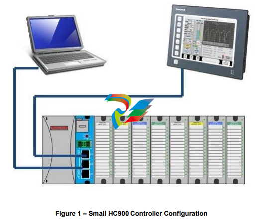
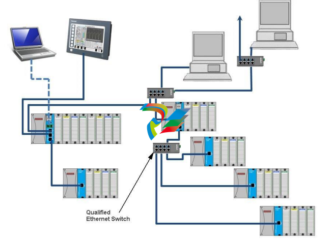
Figure 2 – Expanded HC900 Controller Configuration (C50/C70 CPU only)
The HC900 Controller design enables users and OEMs who are adept in system integration to assemble a system
that fits a broad range of requirements. Any configuration can be readily modified or expanded as requirements
dictate. In initial configuration and in subsequent modifications, the HC900 Controller affords an optimum balance
of performance and economy.
Configurations such as those shown in Figure 1 and in Figure 2, as well as many variations, can be assembled from
modular components. Many of the components are available from Honeywell, and some are available from thirdparty suppliers. These modular components are available in any quantity and mix that make the most sense for a
given application.
As indicated in Figure 3, the HC900 Controller includes provisions for communication via Ethernet with host
systems such as the Honeywell Experion HMI and other HMI software that supports Ethernet Modbus/TCP
protocol. Also, the communication structure of the HC900 Controller enables remote placement of input/output
components, allowing significant economies in cabling and wiring.
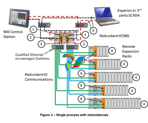
Redundant CPUs - Redundancy is provided by two C75 CPUs operating in a controller rack; this rack has no
I/O. A Redundancy switch module (RSM) sits between the CPUs.
Redundant CPU Power - Two power supplies, P01 and P02 one for each C75 CPU. Model numbers are 900P01-
0101, 900P01-0201, 900P02-0101, 900P02-0201
Redundant CPU-I/O connection – Each CPU has its own 100 base-T Ethernet physical communication link with
one or more racks of I/O. Multiple I/O racks require Ethernet switches.
I/O racks – 5 racks shown, top to bottom: 4-slot w/1 power supply, 8-slot w/1 power supply, 12-slot w/1 power
supply, 8-slot w/redundant power supplies, 12-slot w/redundant power supplies. A Power Status Module (PSM) is
required with redundant power supplies. High and low capacity power supplies are available.
Dual Networks for Host communications - Dual Networks for Host communications are provided on the C75 CPU.
Both network ports are continuously active on the Lead controller. The network ports on the Reserve CPU are not
available for external communications. Experion HS and the 900 Control Station (15 inch model) support Dual
Ethernet communications and automatically transfer communications to the opposite E1/E2 port during a network
failure. Connections to these ports are to be considered part of the control network layer and as such care must be
taken to reduce exposure to uncontrolled/ unknown network communications. A properly configured firewall such as
the MOXA EDR-810 is recommended to help mitigate the exposure.
Scanner 2 module – has 2 ports, one for each CPU connection to I/O. This IO network between the controllers
and scanners is considered proprietary with no other Ethernet traffic.
Feature Summary
Hardware
Modular rack structure; components are ordered individually as needed
CPU with Ethernet and isolated RS485 communications
Easy to assemble, modify, and expand
C30 and C30S controllers provide local I/O connections while C50/C70 and C50S/C70S Controllers provide for
remote input/output rack connections over a private Ethernet-linked network
Parallel processing - a microprocessor in each I/O module performs signal processing, to preserve update rates
Power supplies - provide power to CPU rack and Scanner I/O racks
Redundancy
Redundant C75 CPU
Redundancy Switch Module (RSM) – required between redundant CPUs
Redundant Power Supply – provides redundant power to any CPU rack or Scanner2 I/O rack
Power Status Module (PSM) – required when using a second power supply in Scanner2 I/O rack
Communications
All CPUs (except where noted):
Serial Ports:
Legacy
Two serial ports, configurable for RS-232 or galvanically isolated RS-485 communications.
RS232 port can be used for link to PC for 900 Designer configuration tool (up to 50ft/12.7 Meters)
or via modem. Also can be configured for Modbus RTU, master or slave.
RS 485 port used for 2 wire link to legacy operator interface (ELN protocol) or can be configured
for Modbus RTU, master or slave communications (up to 2000 Ft /600 Meters).
New Controllers
Two isolated RS 485 communications ports
USB to RS485 cable must be obtained to support link to PC for 900 Designer configuration tool
Can be configured for Modbus RTU, master or slave communications (up to 2000 Ft /600 Meters)
Ethernet 10/100 Base-T connection:
Port(s) configured to Auto Negotiate - default to half duplex
C30/C30S controller up to 5 PC hosts via Modbus/TCP protocol. C50/C50S, C70/C70S and
C70R Legacy and C75/C75S (new model) support up to 10 PC hosts via Modbus/TCP protocol.
Peer-to Peer (UDP) communication with up to 32 other HC900 Controllers.
C70/C70S and C70R Legacy and C75/C75S (new model) have 2 Ethernet ports for connection to
up to 10 PC hosts. They also support Modbus/TCP Initiator function over both ports and
automatically switch between ports to maintain Peer to Peer communications with other
C70/C70S or C70R/C75/C75S redundant CPUs.
Private Ethernet 100 base T connection to I/O expansion racks: (except C30 and C30S CPU)
Direct connection to each C70R Legacy and C75/C75S (new model) CPU.
For more information
For complete feature summary and specifications see Specifications on page 206.
Components and Architecture
Overview
This section provides a description of each of the major components that can be included in an HC900 Controller
physical configuration, and indicates some of the methods by which they can be combined.
Components
The Honeywell HC900 Process Controller includes a set of hardware modules that can be combined and configured
as required for a wide range of small to medium process control applications.
Some of the modules are required in all configurations. Others are optional; they are selected as appropriate to
provide optional functions and/or to "size" the system, either in initial planning, or in modifying and/or expanding
the system to meet changing requirements.
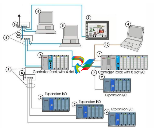
An HC900 Controller configuration with multiple controllers is illustrated in Figure 4.
This illustration includes key-numbers that identify components that are described in Table 2
CAUTION
Communications lockout is possible in high network traffic conditions.
Extraneous traffic is possible when sharing bandwidth with other devices. We recommend putting the
controller on a private network segment. Failure to do so could, in high traffic cases, result in
communications lockout requiring the controller to be power-cycled.
Note: The HC900 is equipped with an Ethernet port as a standard feature (two Ethernet ports on the C70
& C75 CPU). These ports can function simultaneously as slave and master communications ports.
The dual Ethernet ports (C70 & C75 CPU’s) can be configured for redundant operation to a host.
If the host device does not have the inherent capability to recognize a network failover, the
Honeywell HWIOPC Server would be used to perform this functionality.
The dual Ethernet ports will not operate in a redundant configuration through a gateway to a
Host / server on another subnet. While both the E1 & E2 Ethernet can be configured with a default
Gateway address, only the E1 port will actually communicate across a gateway to another subnet
Hardware Components
This section contains general descriptions of each of the major components of the HC900 system.
For environmental specifications, refer to the section on Pre-Installation Planning.
HC900 Controller Rack
An HC900 Controller ("local rack") is shown in the following figure. As indicated in this figure, the Controller Rack
includes:
1. Rack, available in 4- 8-, or 12-slot versions
2. Power Supply
3. Controller Module
4. Grounding bars (for I/O wiring; optional)
5. Input/Output modules.
6. I/O Terminal Blocks

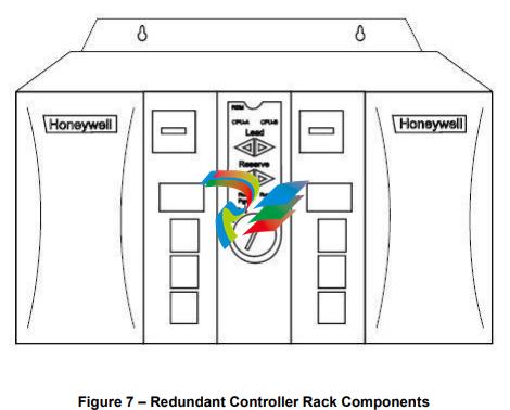
HC900 Redundant Controller Rack
A HC900 Redundant Controller is shown in the following figure.
1. Rack
2. Redundancy Switch Module (RSM) . Interface between Lead/Reserve controllers.
3. Lead/Reserve controllers. Two C75 CPUs, designated “CPU-A” (left), “CPU-B” (right).
4. Two 900P01-xxxx or 900P02-xxxx Power Supplies.
-
 HIRSCHMANN MSM20-M2M2M2M2SY9HH9E Ethernet media modul
 -
 HIRSCHMANN SPIDER-PL-20-05T1999999TWVHHHH Industrial Ethernet Rail Switch
 -
 Hirschmann SPIDER-PL-20-07T1M2M299TWVHHHH Industrial ETHERNET Rail Switch
 -
.png) Hirschmann (Belden) RS20-1600M2M2SDAEHC09.1.00 DIN-rail managed industrial Fast Ethernet switch
Hirschmann (Belden) RS20-1600M2M2SDAEHC09.1.00 DIN-rail managed industrial Fast Ethernet switch -
 Hirschmann (Belden) RS30-1602O6O6TDAPHC09.1.00 DIN-rail managed industrial Ethernet switch
 -
 Hirschmann (Belden) RS30-2402O6T1SDAPHH09.0.13 DIN-rail industrial Ethernet switch
 -
Hirschmann (Belden) SPIDER-PL-20-04T1S29999TY9HHHH Ethernet DIN-rail switch
-
 HIRSCHMANN RS20-1600T1T1SDAUHX Switch
 -
 HIRSCHMANN BRS42-0012OOOO-SPCZ99HHSES industrial switch
 -
 Hirschmann RS20-0800S2S2TDHPHH09.0.14 Fast Ethernet DIN rail switch.
 -
 HIRSCHMANN MM20-Z6Z6M2M2SAHH Hybrid Fast Ethernet Media Module
 -
 HIRSCHMANN MM20-Z6Z6T1T1SAHH hot-swappable hybrid Fast Ethernet Media Module
 -
 HIRSCHMANN MM20-P9P9T1T1SAHH Hybrid Fast Ethernet Media Module
 -
 HIRSCHMANN MM20-M4T1T1T1SAHH Hybrid Fast Ethernet Media Module
 -
 HIRSCHMANN MM20-M4M4T1T1SAHH Hybrid Fast Ethernet Media Module
 -
 HIRSCHMANN MM20-M2M2M2M2SZHH Ethernet media module
 -
HIRSCHMANN MM20-M2M2M2M2SAHH Ethernet media module
-
 HIRSCHMANN MM20-T1T1T1T1EBH 4-port Fast Ethernet Copper Cable Media Module
 -
HIRSCHMANN MM20-T1T1T1T1SAHH 4-port Fast Ethernet Copper Cable Media Module
-
HIRSCHMANN MM20-T1T1T1T1SAHH 4-port Fast Ethernet Copper Cable Media Module
-
 HIRSCHMANN MM20-Z6Z6EBH Hot-swappable fast Ethernet media module
 -
 HIRSCHMANN MM20-Z6Z6SAHH Ethernet media module
 -
HIRSCHMANN MM20-Z6Z6Z6Z6EBH Industrial Media Module
-
 MSM40-T1T1T1TZ9HH9E99.9.99 HIRSCHMANN Switch
 -
 HIRSCHMANN MS20-0800SAAEHC / MS20-0800SAAEHC0 8-port modular Layer 2 management Ethernet switch
 -
 Hirschmann RSPM20-4T14T1SZ9HHS9 Switch RSPM20-4T14T1SZ9HHS9
 -
 HIRSCHMANN RS20-1600M2M2SDAEHH09.1. RS20/30/40 Managed Switch configurator
 -
HIRSCHMANN RS20-1600M2M2SDAEHX09.0.00 Ethernet switch
-
 HIRSCHMANN BELDEN SPIDER-PL-20-07T1M2M299TY9HHHH / SPIDERPL2007T1M2M299TY9HHHH
 -
HIRSCHMANN MM3-1FXS2/3TX1 Switching Board Module
-
 HIRSCHMANN RSPE30-24044O7T99-ECCP999HHSE2A08.1.00 Industrial-grade fanless management-type Ethernet switch
 -
 HIRSCHMANN RS30-1602OOZZSDAEHC09.1.00 DIN-rail-mounted managed Layer 2 Ethernet switch
 -
 HIRSCHMANN MACH104-20TX-F Managed 24-port Full Gigabit 19" Switch
 -
 HIRSCHMANN Switch RS20-0800M4M4SDAE
 -
Hirschmann RS30-1602O6O6SDAEHH09.1. Management-type Ethernet switch
-
 Hirschmann RS30-1602OOZZSDAEHC09.0.10 Open rack-style Ethernet switch
 -
 HIRSCHMANN RSPE30-24044O7T99-SCCV999HHSI2SXX.X.XX High-Availability Seamless Redundancy
 -
HIRSCHMANN RSPE30-24044O7T99-SCCZ999HHSE2A DIN-rail Ethernet switch
-
HIRSCHMANN MM2-4TX1-EEC switch
-
HIRSCHMANN MSM40-T1T1T1T1TZ9HH9E99.9.99 Module
-
 HIRSCHMANN RS20 Rail Switch RS20-0400S4T1SDAEHC07.1.01
 -
 HIRSCHMANN M4-FAST8-SFP Fast Ethernet media module
 -
 HIRSCHMANN RS20-0400M2T1SDAP Managed Fast-Ethernet-Switch
 -
 HIRSCHMANN BELDEN SPIDER II 8TX/1FX EEC Industrial Ethernet Rail Switch
 -
HIRSCHMANN MM3-2FXS2/2TX1
-
 HIRSCHMANN RS2-4TX/1FX EEC Industrial Ethernet Rail Switch
 -
 RS30-0802O6O6SDAEHC09.0.10 HIRSCHMANN Switch
 -
 HIRSCHMANN m4-8TP-RJ45 Ethernet Media Module
 -
 HIRSCHMANN MSP30-24040SCZ9URHHE3A switch
 -
 Hirschmann rack MS30-1602SAAPHC
 -
 HIRSCHMANN RS2-FX/FX Industrial Switch Module
 -
Rs1txfx - Hirschmann - Rs1-Tx/Fx Rail Switch
-
RS20-0800S2S2SDAEHC09.1.00 HIRSCHMANN Commutator
-
 Hirschmann EAGLE20 TX/TX Industrial Security Router
 -
 Hirschmann SPIDER-SL-20-04T1S29999SY9HHHH Industrial Switch
 -
 HIRSCHMANN MAR1040-4C4C4C4C9999SMMHRHHXX.X. Gigabit Ethernet Switch configurator
 -
 Hirschmann MAR1040 Industrial Switch
 -
 HIRSCHMANN BELDEN RS30-1602O6O6SDAE
 -
Hirschmann RS20-1600M2M2SDAUHC Ethernet DIN rail switch
-
 HIRSCHMANN OCTOPUS 24M industrial switch
 -
 HIRSCHMANN RS20-1600T1T1SDAE Management-type Ethernet switch
 -
 HIRSCHMANN RS20-1600T1T1SDAUHH industrial switch
 -
HIRSCHMANN RS20-0800M2M2SDAPHC09.0.04 switch
-
 Hirschmann MR 8-03 24V DC Industrial Modular Bridge/Router
 -
 HIRSCHMANN RS20-0400M2T1SDAPHC08.0.01 Managed Switch
 -
 MACH1130 Hirschmann Industrial Switch
 -
 HIRSCHMANN 943824-002 SPIDER 5TX Industrial Ethernet Switch
 -
 HIRSCHMANN RS30-0802O6O6SDAEHC09.1.00 Managed Industrial Switch
 -
 HIRSCHMANN RS20-0400M2M2TDAEHC04.0.01 Industrial Switch
 -
 HIRSCHMANN BRS20-0600Z6Z6-STCZ99HHSES Industrial Switch
 -
 HIRSCHMANN MACH104-20TX-FR-L3P Industrial Ethernet Switch
 -
 HIRSCHMANN RS40-0009CCCCEDBPHH06.0.01 Industrial Switch
 -
 HIRSCHMANN RS2-3TX/2FX EEC Industrial Ethernet Switch
 -
 Hirschmann MACH 1020/1030 Fast/Gigabit Rack Mount Switches
 -
HIRSCHMANN RS20-0800M2M2SDAPHC09.0.14 Industrial Switch
-
 HIRSCHMANN RS20-1600T1T1SDAEHC09.0.04 Industrial Switch
 -
 HIRSCHMANN RSB20-0800T1T1EAABHH Industrial Switch
 -
 HIRSCHMANN MACH4002-48+4G-L3E Industrial Backbone Switch
 -
 HIRSCHMANN RS20-0400S2T1SDAE Industrial Managed Switch
 -
HIRSCHMANN RS20-0800S2T1SDAUHC Industrial Switch
-
 HIRSCHMANN RS20-2400S4S4SDAEHC09.0.14 industrial switch
 -
 HIRSCHMANN OS20-001200T5T5T5- TBBZ999HHNE3S 08.1.00 industrial switch
 -
HIRSCHMANN OS20-001200T5T5T5- TBBZ999HHNE3S 08.1.00 industrial switch
-
 HIRSCHMANN RS40-0009CCCCSDAEHH09.0.14 switch
 -
 Hirschmann RS20-1600T1T1SDAUHC Management-type Ethernet Switch
 -
 Hirschmann M1-8SFP Switche
 -
Hirschmann Industrial Ethernet Ruggedized Switch MACH1000 Family
-
 Basler Electric, Solid State Protective Relay, BE1-60
 -
BASLER ELECTRIC SR4A-2B15B3A Static Voltage Regulator
-
.png) BASLER ELECTRIC EXCITER DIODE MONITOR EDM-200
BASLER ELECTRIC EXCITER DIODE MONITOR EDM-200 -
.png) BASLER ELECTRIC DECS125-15-B2C5 DIGITAL EXCITATION CONTROL SYSTEM V 2.0.9
BASLER ELECTRIC DECS125-15-B2C5 DIGITAL EXCITATION CONTROL SYSTEM V 2.0.9 -
 BASLER ELECTRIC BE1-851 OVERCURRENT PROTECTION RELAY MECHANISM
 -
 Basler Electric BE1-51A / BE151A
 -
 Basler Electric BE1-40Q Loss of Excitation Relay
 -
 Basler Electric BE1-87G Variable Percentage Differential Relay
 -
 Basler Electric BE1-11 Protection System I5A3M2P2N0EA00
 -
 BASLER ELECTRIC DECS-200-1C Digital Excitation Control System
 -
 Basler Electric / Kohler BE1-11g Generator Protection Relay G5A3M2J2N0E000
 -
BASLER ELECTRIC DECS125-15 DIGITAL EXCITATION CONTROL SYSTEM
-
 BASLER ELECTRIC BE1-951 OverCurrent Protecton System
 -
Basler Electric DECS-200-1L Digital Excitation Control System
-
 Basler Electric DGC-2020HD-5NS1DNSBA Digital Genset Controller -
 -
 BASLER ELECTRIC BE1-81T1EE1WA0N1F / BE181T1EE1WA0N1F
 -
 BASLER ELECTRIC BE1-25M1EA6PN5R1F / BE125M1EA6PN5R1F
 -
 BASLER ELECTRIC DECS-250-LN1SN1N DIGITAL EXCITATION CONTROL SYSTEM
 -
Basler Electric DECS-250-CN2CN 1N Digital Excitation Control System Unit
-
 BASLER ELECTRIC DECS-300-C0N0 DIGITAL EXCITATION CONTROL SYSTEM
 -
 BASLER ELECTRIC BE1-87T-A1E-A1J-D0S1F / BE187TA1EA1JD0S1F
 -
BASLER ELECTRIC BE1-11-G6D1M0J2P0E000 Protection System
-
 BASLER ELECTRIC BE1-GPS100-E4N1H1N GENERATOR PROTECTION SYSTEM
 -
 Jaquet Relay card (Auxiliary module) FTV 3090 377Z-03985
 -
 Jaquet Trip Chain Control card FTBU 3034 377Z-05030
 -
 Jaquet with input card -E04 FTFU 3024 -E04 377Z-05855
 -
 Jaquet with input card -E03 FTFU 3024- E03 377Z-03983
 -
 Jaquet FTFU 3024- E02 377Z-03982 with input card -E02
 -
 Jaquet FTFU 3024-E01 377Z-03981 with input card -E01
 -
 Hirschmann RS20-2400T1T1SDAE Industrial Managed Ethernet Switch
 -
 Hirschmann BELDEN EAGLE30-04022O6TT999SCCV9HSE3F
 -
 Hirschmann MM3-2FXS2/2TX MICE Media Module
 -
 Hirschmann RS20-1600M2M2SDAPHC08.0.05 Industrial Managed Switch
 -
 Hirschmann OZD Profi 12M G12-1300 PRO Fieldbus Repeater
 -
Hirschmann SPIDER 4TX/1FX-ST EEC Industrial Ethernet Switch
-
 Hirschmann MM2-2FXM3/2TX1 MICE Media Module
 -
 Hirschmann RS20-2400M2M2SDAPHC09.0.14 Industrial Switch
 -
 Hirschmann RS20-0400M2M2SDAEHC07.1.05 OpenRail Switch
 -
 Hirschmann OZD Profi 12M G12-EEC Fieldbus Repeater
 -
HIRSCHMANN MDA422-1/2-3.5c-23/46 sensor
-
Hirschmann RS30-2402T1T1SDAUHC Managed Industrial Switch


