MotorolaMVME6100 Single Board Computer Installation and Use P/N: 6806800D58E March 2009
nor addressable. This issue will be resolved at a later date.
Other functions, such as Ethernet and SCSI interfaces, are function independent of the
Winbond IDSEL line. The wide SCSI interface can only be supported through IPMC connector
J3.
PMC mode is backwards compatible with the MVME5100 and MVME5500 and is accomplished
by configuring the on-board jumpers.
1.3 Getting Started
This section provides an overview of the steps necessary to install and power up the
MVME6100 and a brief section on unpacking and ESD precautions.
Overview of Startup Procedures
The following table lists the things you will need to do before you can use this board and tells
where to find the information you need to perform each step. Be sure to read this entire
chapter, including all Caution and Warning notes, before you begin.
Table 1-1 Startup Overview

Unpacking Guidelines
Unpack the equipment from the shipping carton. Refer to the packing list and verify that all
items are present. Save the packing material for storing and reshipping of equipment.
If the shipping carton is damaged upon receipt, request that the carrier’s agent be present
during the unpacking and inspection of the equipment.
1.4 Configuring the Hardware
This section discusses certain hardware and software tasks that may need to be performed
prior to installing the board in a chassis.
To produce the desired configuration and ensure proper operation of the MVME6100, you may
need to carry out certain hardware modifications before installing the module.
Most options on the MVME6100 are software configurable. Configuration changes are made
by setting bits in control registers after the board is installed in a system.
Avoid touching areas of integrated circuitry; static discharge can damage circuits.
Emerson strongly recommends that you use an antistatic wrist strap and a conductive foam
pad when installing or upgrading a system. Electronic components, such as disk drives,
computer boards, and memory modules can be extremely sensitive to electrostatic
discharge (ESD). After removing the component from its protective wrapper or from the
system, place the component flat on a grounded, static-free surface (and, in the case of a
board, component side up). Do not slide the component over any surface.
If an ESD station is not available, you can avoid damage resulting from ESD by wearing an
antistatic wrist strap (available at electronics stores) that is attached to an active electrical
ground. Note that a system chassis may not be grounded if it is unplugged.
Inserting or removing modules with power applied may result in damage to module
components.
Dangerous voltages, capable of causing death, are present in this equipment. Use extreme
caution when handling, testing, and adjusting.
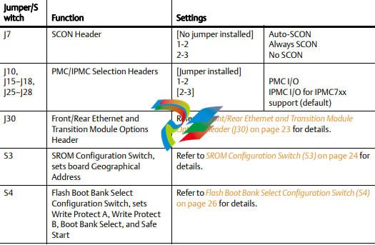
Jumpers/switches are used to control those options that are not software configurable. These
jumper settings are described further on in this section. If you are resetting the board jumpers
from their default settings, it is important to verify that all settings are reset properly.
Figure 1-1 illustrates the placement of the jumpers, headers, connectors, switches, and various
other components on the MVME6100. There are several manually configurable headers on the
MVME6100 and their settings are shown in Table 1-2. Each header’s default setting is enclosed
in brackets. For pin assignments on the MVME6100, refer to Chapter 5, Pin Assignments.
Items in brackets are factory default settings.
Table 1-2 Jumper and Switch Settings


