
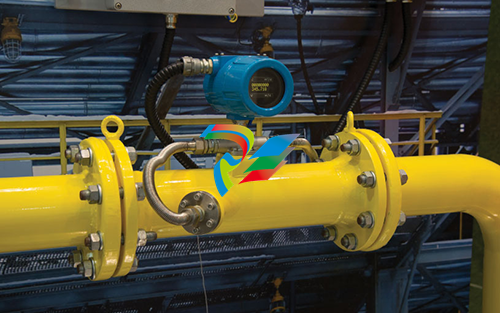
Instrumentation Lessons: Selecting and Sizing Flowmeters
No two flow measuring applications are the same, and two nearly identical flowmeter products can differ in how the accuracy is measured.
Flow rates and flow totals are two of the key types of measurements used in process facilities around the world. No matter the process industry, there will always be a wide variety of flow measurements that must be made for monitoring, control, and regulatory purposes. However, the appropriate selection and sizing of flowmeters are not something we can always take for granted.
Like any piece of equipment, instrumentation must be carefully selected so the measurements will be as accurate and repeatable as possible. Flowmeters are no exception. In industries where low-bid design and construction services are commonly used, it is even more important that the main aspects of properly sizing flowmeters are taken into account. In this article, we explain key considerations of sizing a flowmeter from the perspectives of accuracy, repeatability, and rangeability, as well as common installation pitfalls to avoid.
The measurement goal
The first aspect to think about when sizing a flowmeter is the expected flow range. Whether a flow rate is expected to be a fairly consistent narrow range, or the rate is expected to vary widely has a substantial effect on how a flowmeter should be sized.
In general, when sizing a flowmeter, conditions to consider include:
shutdown or rest state (and if the line will tend to drain)
the normal startup progression
the normal operating range (steady state)
the extreme operating range (steady state)
normal shutdown progression
any expected possible abnormal conditions.
A way to do this is by estimating a flow envelope using a table such as the sample shown in Table 1.

Accuracy versus repeatability versus rangeability
After the flow envelope has been determined for a flowmeter, the next aspect to consider is how well a proposed flowmeter can measure the flow. “Accuracy” refers to how close the flowmeter reading is to the actual flow value. “Repeatability” (also known as precision) is how consistent readings are over time. Accuracy and repeatability are not the same. The difference between accuracy and repeatability is shown in Figure 1.

Another way to understand the difference between accuracy and repeatability is to imagine two archers shooting at a conventional archery target. Suppose one archer hit the bull’s-eye consistently. Because he was always accurate, the shots were repeatable. Now imagine an archer who hit the target but consistently missed the bull’s-eye. Although the archer had good repeatability, he was not accurate. Good repeatability does not guarantee accuracy. If you do not see a proper accuracy statement on equipment, (i.e., there is only a repeatability statement), be cautious.
A flowmeter with good repeatability (but poor accuracy) can be adjusted to read more accurately. However, a flowmeter with poor repeatability cannot be adjusted, because there is no consistency in the readings.
“Rangeability” is a measure of how accurate and how repeatable the flowmeter will be over the expected range of flow readings. Some flowmeters are better at turndown (being able to read very low flow rates) than others. Thus, whenever an accuracy claim is being made for a flowmeter, it is important to look at the expected flow range accuracy that the vendor is guaranteeing.
Before looking at some of the more common flowmeter selection/sizing pitfalls, here is a more detailed discussion about defining accuracy and repeatability.
Accuracy impacts
It pays to read the fine print when it comes to accuracy claims (or specifications) associated with instrumentation such as flowmeters. At lower flow rates, the accuracy often drops off significantly. For example, if an instrument has an accuracy claim of 0.5 percent of full scale, it is important to recognize that the actual accuracy diminishes as the operating conditions fall below the full-scale setting.
Another way of stating accuracy is to define it in terms of the reading, such as ±0.5 percent of the reading over a certain part of the flowmeter’s range. Depending on the range in which the flowmeter is used, this stated accuracy could be either negligible or a significant difference. On flowmeters used for billing or other revenue-related purposes, the meter’s accuracy can have a major financial impact.
Imagine that a paddle-wheel flowmeter claims to have an accuracy of ±0.5 percent. Suppose further that it is a percent of the full range, and the full range is 50 feet per second (ft/s). If the flow range where you will use it is 6 ft/s, which is common in wastewater treatment plants, the actual accuracy is much different than you might expect:
0.005 × 50 f/s = ±0.25 ft/s
If you apply this accuracy against a flow rate of 6 ft/s, the actual accuracy is:
±0.25 / 6 ft/s = ±0.0417, or 4.17%
Comparing a magnetic flowmeter with an accuracy of 0.5% of reading to a doppler flowmeter with an accuracy of 0.5% of full range yields a similar result.
A common problem occurs when a city or municipality uses two different types of flowmeters. Imagine one meter is a highly accurate magnetic flowmeter located in a meter vault to monitor the plant’s effluent flow, and the other is a doppler meter monitoring the influent flow. Doppler flowmeters tend to decline in accuracy as the flow rate drops. Even highly accurate magnetic flowmeters have both extremely high and low reading limits under which they will not operate accurately.
Case histories have shown that the plant appears to be generating wastewater, because the effluent is more than the influent, or something is evaporating the wastewater. We know in both cases that neither of these conditions really exists. What is happening is that the doppler meter is not matching the accuracy of the magnetic meter. The difference between 0.5 percent of 12 million gallons a day (Mgd) and 4.17 percent of 12 Mgd is substantial.
(.0417 – 0.005) × 12 Mgd = 0.44 Mgd, or 305 gal/min
Matters are made even worse if the doppler meter is used for pacing chemical feed into the wastewater with the same inaccuracies; the results are either overdosing or underdosing. Water treatment plants have low, average daily, and high peak demand flows, and further, low and average daily flows occur more frequently. This demonstrates the importance of being cautious in choosing meter types for those flow variables.
Many types of flowmeters suffer in performance as the flows decrease and approach the lower end of their viable flow range. Therefore, pacing during low flow periods may be highly suspect. Chemicals are becoming more costly, analytical instruments for measuring the effects of these chemicals are becoming costly, and corrosion due to underdosing or overdosing wastewater can also be costly to equipment. All of these may contribute to effluent that is a danger to wildlife and, in extended cases, can be harmful to the health of people living in the area.
Repeatability
In many ways, repeatability is even more important than accuracy. If an instrument is consistently wrong (inaccurate, but repeatable), the instrument can be adjusted to read correctly. However, if an instrument is inconsistent with how it reads, no amount of calibration work can fix the poor readings it provides.
Today, many field instruments work on force-balance techniques (where a process reading is converted to a force that then impacts a force-based sensor) such as piezoelectric crystals, capacitance, and strain gauges. These work on the principle that if you put a force on an instrument, there should be no motion even though an electric signal is generated on the output of that instrument. There are still flow, level, and chemical measuring devices that do not work on the force-balance principle, and for these types, looking at the repeatability of that piece of equipment is still important. A steady widening of the repeatability is an indication that something is going wrong with the instrument.
While the accuracy of an instrument can be improved with calibration, repeatability is often something that the design of the instrument defines.
Rangeability and uncertainty
As previously noted, the rangeability of an instrument must be taken into consideration during the sizing and selection part of a plant design. It is important that installed flowmeters can read the various intended flow ranges specific to where they are installed. At a minimum, they must meet the needed accuracy/repeatability for each flow rate for the application.
One of the most common problems with a piece of instrumentation equipment is the exaggeration of its range. How many times have you heard that a meter can read flow rates at velocities of 1 to 100 ft/s, giving the impression that you can read flows accurately through that total velocity range?
What often goes unmentioned is that the particular meter’s accuracy has a 10:1 turndown ratio. This means that a meter sized to measure a range of 0 to 30 Mgd has a true accuracy over the full range of 3 to 30 Mgd. Below 3 Mgd, the meter accuracy diminishes.
Additionally, different types of meters have different turndown ratios over their full range. It is common for a Venturi tube, for example, to have two transmitters measuring the flow. This is because a Venturi tube with one transmitter measures accurately with a 6:1 turndown ratio over the full range. So, if we look at a range of 0 to 30 Mgd, the meter’s accuracy diminishes below 5 Mgd.
The range over which the instrument meets the stated linearity of uncertainty requirements is its “rangeability.” “Uncertainty” is the range of values within which the true values lie with a specified probability. Uncertainty of ±1 percent at 95 percent confidence means the instrument will give the user a range of ±1 percent for 95 readings out of 100.
Another common error occurs during equipment sizing. In the municipal wastewater sector, it is a common practice to assume that solids in wastewater will settle out around a velocity of 2 ft/s. A magnetic flowmeter reads accurately if the minimum velocity is above 2 ft/s, but below this, settling is likely to occur—and then who can say what the accuracy really is?
Designing for now versus the future
Typically, designers size plants to handle increased flow capacities for 20 years. For this reason, designers often oversize pipes for early lifecycle flow, and there is a corresponding settlement inside the pipe. This settling can also occur in the inner liner of the meters. Because these meters are velocity-sensing devices with an assumed constant cross section, they will give a false reading if the inner liner becomes coated with sludge.
A solution may be to reduce the size of the meter to increase velocity by using a pipe reducer on the inlet side and a pipe expansion section on the discharge side of the meter. If possible, avoid connecting the reducer and expander directly to the meter. Manufacturers recommend that when you reduce the pipe, the flowmeter should be placed a minimum of six to 10 pipe diameters upstream from an elbow or valve and at least two pipe diameters downstream of a pipe elbow or valve. This provides a less distorted flow profile for the meter to read.
Be certain you can afford to lose the pressure head when you reduce the meter size. Maximum velocities should not exceed 15 ft/s. By maintaining a minimum scouring effect inside the pipe, your sludge buildup inside pipes and any inline equipment will diminish, helping avoid measurement errors and costly maintenance downtime.
Other common flowmeter traps and pitfalls
Some people ask for the accuracy of a certain flowmeter, level, or pressure-measuring device and, upon hearing a low number, think that everything involved with the flowmeter will be of the same accuracy. However, the meter accuracy is not the accuracy for the entire flow system. A mathematical equation known as the root mean square (RMS) correctly determines the accuracy of the complete system. Consider the case of a magnetic flowmeter that records flow locally, sending an analog signal to an operator’s workstation via a programmable logic controller (PLC).
One must look at each component’s accuracy:
magnetic flowmeter (±0.5%)
magnetic flowmeter transmitter (±0.5%)
wire connection to the recorder (±0.01%)
wire connection to a local control panel terminal block (±0.01%)
the input/output (I/O) card of the PLC (0.4%).
Each component in the system has its own measurement errors and uncertainties that contribute to the overall accuracy of the complete system. In real cases, there could be more components attached to a control system.
To use the RMS method, first square each number, yielding 0.000025, 0.000025, 0.00000001, 0.00000001, and 0.000016. Second, add the numbers. Then find the square root of the sum. The entire system has an accuracy of approximately ±0.00813, or ±0.813 percent instead of 0.5 percent. This accuracy equation works for any individual chemical, pressure, level, temperature or flow loop.
Looking ahead
Remember that no two flow measuring applications are the same. Each has its own unique flow characteristic, range, and accuracy requirements. It is always important to review the expected operating envelope to determine the normal and extended operating ranges to be measured before sizing any flowmeter.
Once the requirements are known, any accuracy, repeatability, or rangeability specifications for possible flowmeter products should always be carefully reviewed. Two nearly identical flowmeter products can have similar sounding accuracy and different details about how the accuracy is measured.
Regardless of the application, it is always recommended to carefully review the requirements and manufacturer literature regarding accuracy and to consider the range, repeatability, turndown ratio, installation requirements, and other aspects. These details make the difference between a well-specified flowmeter and a measurement system that has issues.
Also, depending on the application, it may be worthwhile to do more advanced simulations, to perform RMS error analysis, or to look at installed examples. Lastly, do not be afraid to make use of application engineering services offered by most leading flowmeter vendors.
Like many things in life, it is worthwhile to do some homework when it comes to sizing and selecting flowmeters. It always pays to do the background work up front to ensure that a flowmeter is able to measure the flow and meet the needs of the application.
-
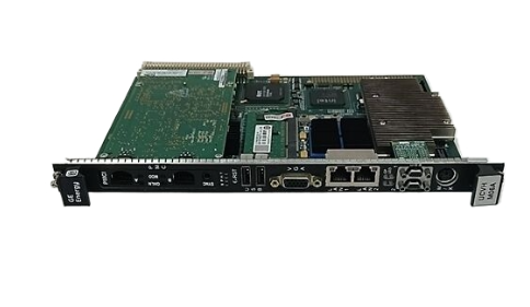
 D20MIC10BASE-T 820-0756 Network card
 -
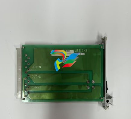
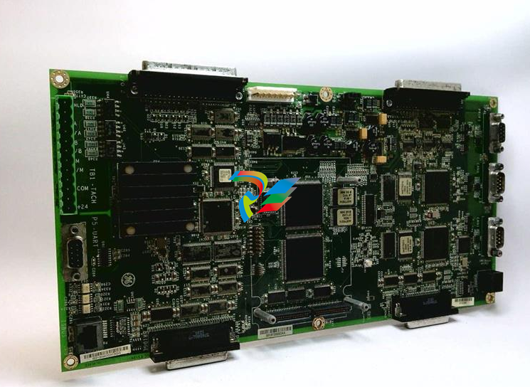 WES13-3 5167-0001-0210 CPU/Auxiliary Control board
 -
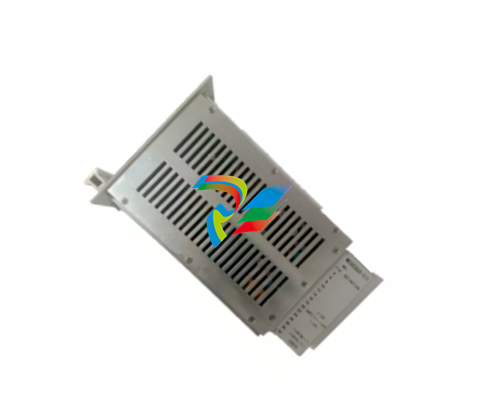
 WES13-3 2508-21001 Embedded digital module
 -
D20ME 526-2005-216943 control module
-
 D20EME 0526-21170-1 Enhanced Master Communications Module for D20 Substation RTUs
 -
.jpg) 2400-21004 / 2010-3101-0442 – Redundant Power Supply Module for Mark VIe Turbine Control
2400-21004 / 2010-3101-0442 – Redundant Power Supply Module for Mark VIe Turbine Control -
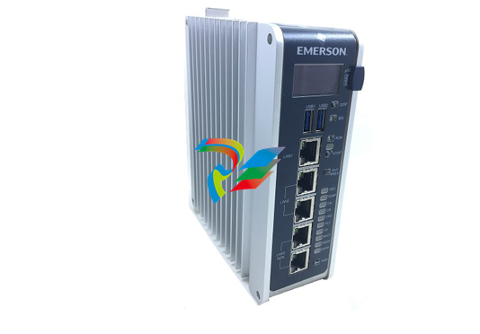 PACSystems™ IC695CPE400 RX3i 64 MB
 -
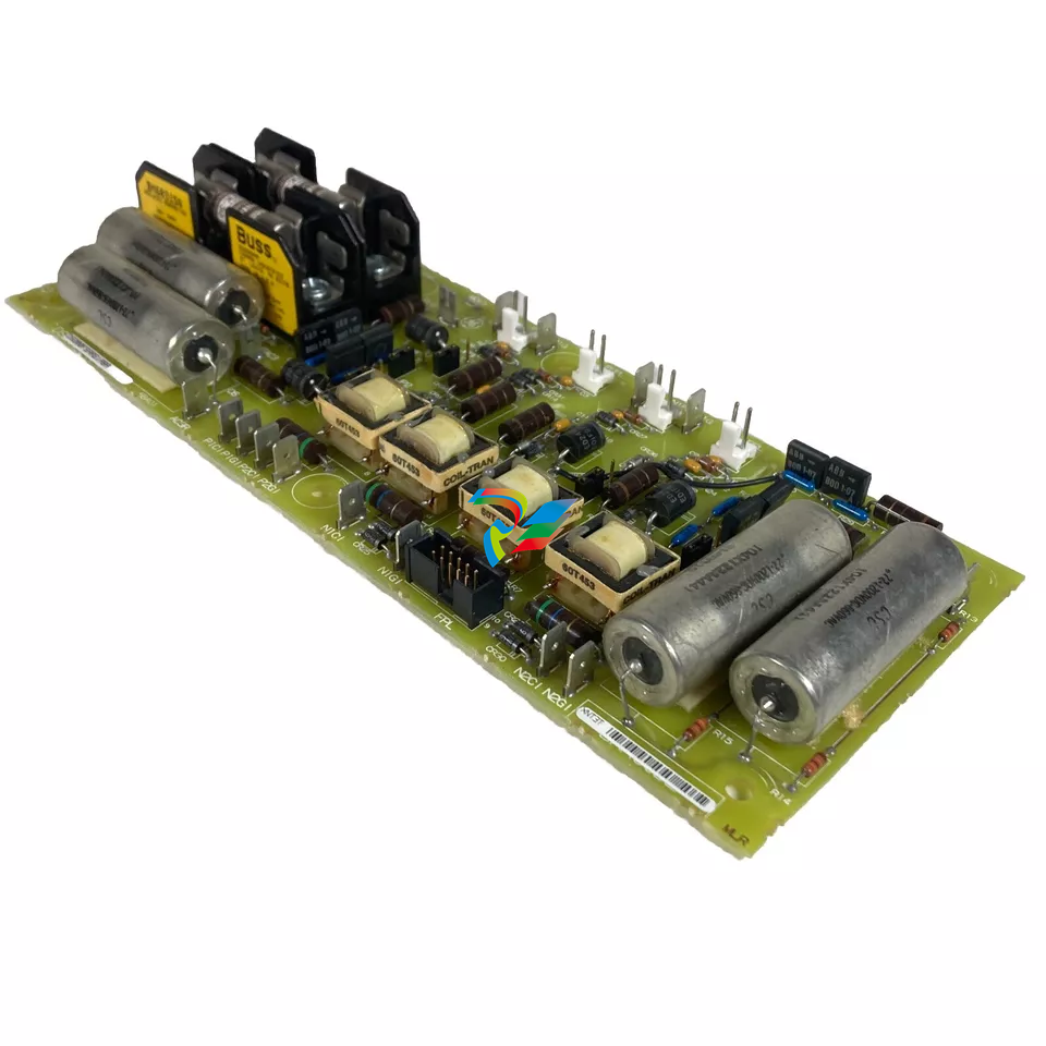
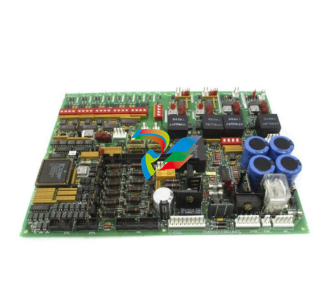 DS200DCFBG2BNC DC2000 DC Feedback Board
 -
 OLDI Ethernet interface module 56SAM-844
 -
 IS200BPPBH2CAA Mark VIe Power Supply Module
 -
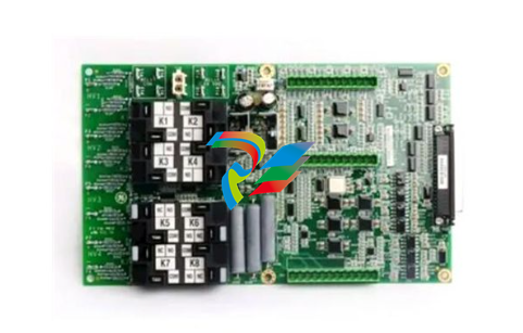
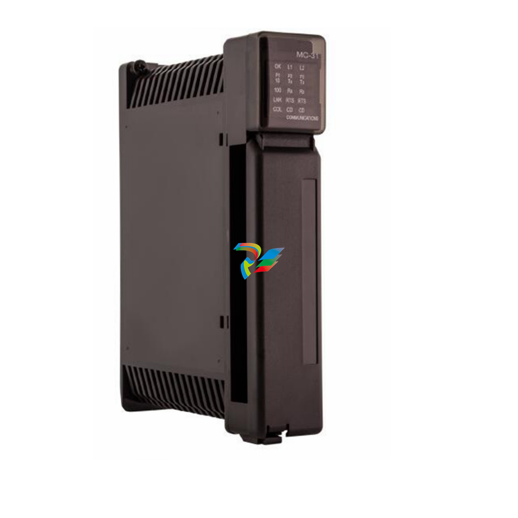
 IS210MACCH2AEG Motor Control and Communication Module
 -
 IS210MACCH2AGG Mark VIe Speedtronic Turbine Control Module
 -
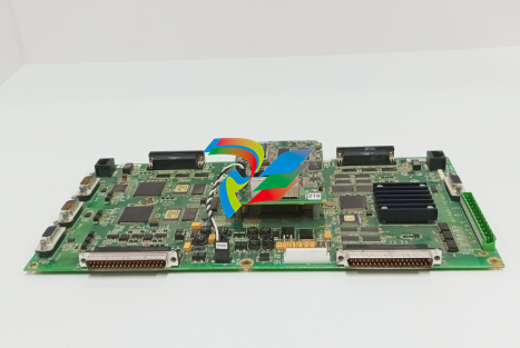
 IS200AEPAH1AFD Printed circuit board
 -
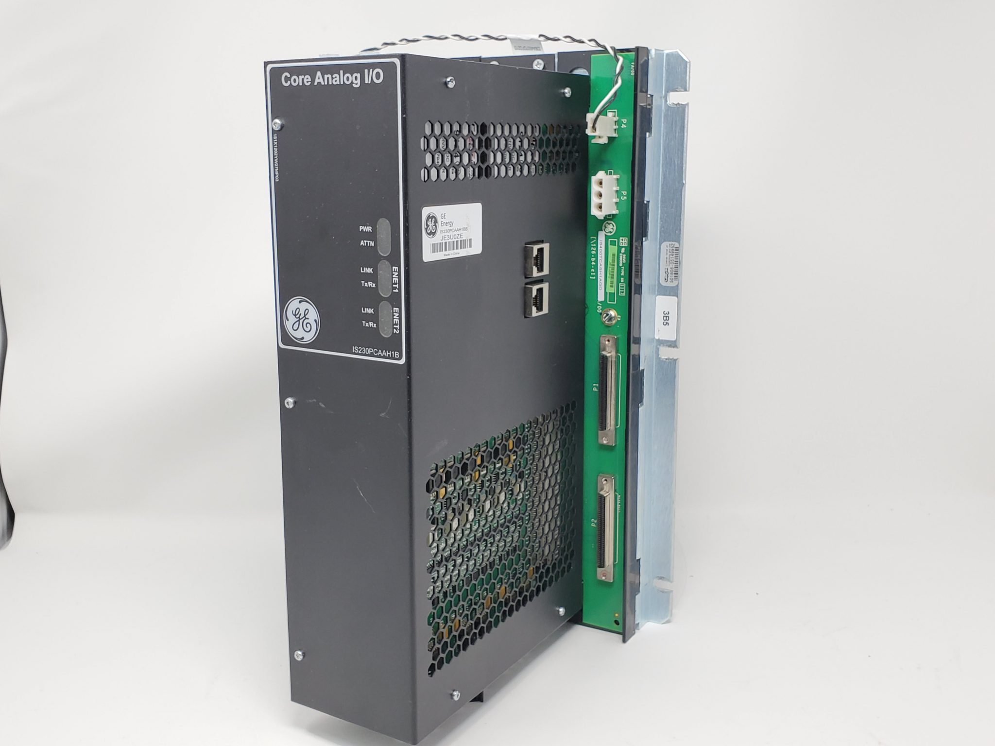
IS200AEPAH1ACB Analog I/O Module
-
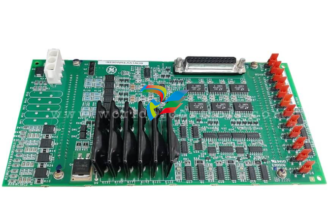 IS200WREAS1ADB AERO TRIP TB DBRD sub-board
 -
 IS200WETAH1AEC large board component made Mark VI system
 -
 IS200AEPAH1AHD A High-Precision Excitation Control Board for Turbine Systems
 -
 IS200WEMAH1AEA Control board
 -
IS210MACCH1AGG processor card
-
 IS230TNRLH1B Discrete Output Modular Assembly
 -
 Mark V Series DS200PCCAG1ACB PCB Power Connect Card
 -
 DS200SI0CG1AEA Instantaneous overcurrent card
 -
 DS200SHVMG1AGE Analog I/O board
 -
 DS200SI0CG1A6A Input/Output Module
 -
 DS200SHVMG1AFE SCR High Voltage Interface Board
 -
 DS200RT8AG3AHC Relay Output Terminal Board
 -
 DS200FSAAG1ABA PCB Field Supply Gate Amplifier Board
 -
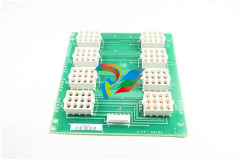
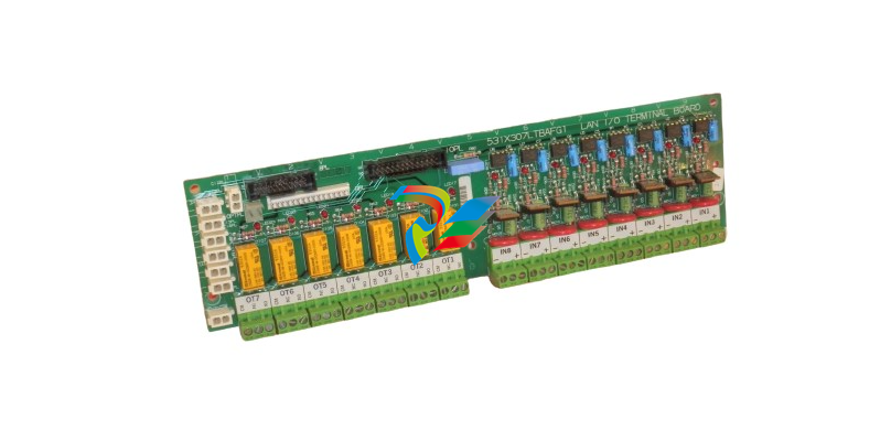 531X307LTBAFG1 F31X307LTBA LAN I/O Terminal Board
 -
 ABB AFS670 19" Ruggedized Switch AFS670-EREEDDDSSEEEEEEEPZYX05.1.0
 -
 NI Controller for VXI VXIPC-871B
 -
 IS200EPMCH1GE Mark VIe Patch Cord Power Distribution Card
 -
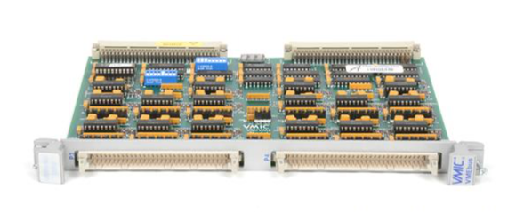
 VMICPCI-7632-03310 IS215UCCAH3A 350-657362-003310J GE gas turbine system control processor board
 -
 WEA13-13 2508-21001 Control Module / I/O Board
 -
WES5120 2340-21004 Controller Main Module
-
 WES5120 2340-21006 Field Controller Master Unit Module
 -
WESDAC D20ME 18-MAR-13 Excitation Control Module
-
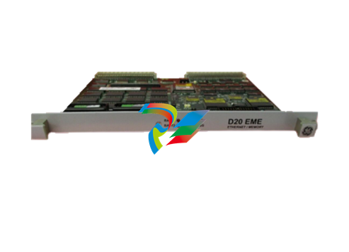
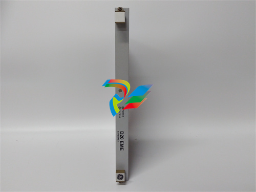 D20 EME 2400-21004 Ethernet communication and expansion module
 -
 GE DS3800XTFP1E1C Thyristor Fan Out Board Brand
 -
 GE SR745-W2-P1-G1-HI-A-L-R-E Feeder protection relay
 -
 GE IS230TNDSH2A Discrete Output Relay Module Brand
 -
 GE Fanuc IS200TDBSH2ACC Mark VI Terminal Board Brand
 -
 GE PMC-0247RC-282000 350-93750247-282000F Disk Drive
 -
GE PMC-0247RC-282000 350-93750247-282000F Disk Drive
-
 GE VMIVME-1150 Serial Communications Controller
 -
 GE VMIVME-5576 Fiber-Optic Reflective Memory with Interrupts
 -
 GE VMIC Isolated Digital Output VMIVME-2170A
 -
 GE MULTILIN 760 FEEDER MANAGEMENT RELAY 760-P5-G5-S5-HI-A20-R-E
 -
GE IS200AEPAH1BKE IS215WEPAH2BB Printed circuit board
-
 GE IS210BPPCH1A Mark VIe I/O Pack Processor Card
 -
 GE IS220PRTDH1A 336A4940CSP6 High-Performance RTD Input Module
 -
GE IS220PDIAH1BE 336A5026ADP4 Discrete Input Module
-
 GE IS420ESWBH3A IONET Switch Module
 -
 GE 516TX 336A4940DNP516TX 16-port Ethernet switch
 -
 GE EVMECNTM13 Embedded control module
 -
GE EVPBDP0001 EVPBDP032 control module
-
 GE Hydran M2-X Enhanced Monitoring with Extended Sensor Life
 -
 GE UR6CH Digital I/O Module
 -
 GE IC695CPU315-CD Central processing unit
 -
 GE 531X305NTBAMG1 DR Terminal Board
 -
 GE 531X305NTBALG1 NTB/3TB Terminal Board 531X Series
 -
 GE 531X305NTBAJG1 NTB/3TB Terminal Board.
 -
GE 531X305NTBAHG1 NTB/3TB Terminal Board 531X
-
 GE 531X305NTBAEG1 is a PCB that functions as a DR terminal board.
 -
General Electric 531X305NTBACG1 NTB/3TB Terminal Board 531X
-
 GE Digital Energy D20 Analog Input Module
 -
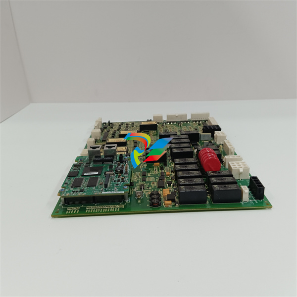
 GE 94-164136-001 main board Control board
 -
 GE 269 PLUS-D/O-100P-125V Digital motor relay
 -
 GALIL DMC-9940 High-performance motion controller
 -
FUJI NP1BS-08 base plate
-
 FUJI NP1Y32T09P1 Transistor drain type digital output module
 -
 FUJI NP1Y16R-08 Digital Output Module
 -
 FUJI NP1X3206-A High-speed digital input module
 -
 FUJI NP1AYH4I-MR current output module
 -
 FUJI NP1S-22 Power module redundancy
 -
 FUJI RPXD2150-1T servo drive module
 -
 FUJI FVR008E7S-2UX Ac frequency converter
 -
 FUJI Ac frequency converter FVR008E7S-2
 -
 FUJI FVR004G5B-2 Small general-purpose frequency converter
 -
 FUJI A50L-2001-0232 Industrial control module
 -
 FUJI A50L-001-0266#N High-performance servo amplifier
 -
 Honeywell FS7-2173-2RP Gas sensor
 -
 Honeywell 10106/2/1 Digital Input Module in Stock
 -
FRCE SYS68K CPU-40 B/16 PLC core processor module
-
Foxboro FBM I/O cards PBCO-D8-009
-
 Foxboro AD916AE Digital Control System (DCS) Module
 -
 GE SR750-P5-G5-S5-HI-A20-R-E Multilin Relay
 -
.jpg) FOXBORO H90 H90C9AA0117S Industrial Computer Workstation
FOXBORO H90 H90C9AA0117S Industrial Computer Workstation -
FOXBORO RH928AW | I/A Series Relay Output Module
-
.jpg) Foxboro N-2AX+DIO Multi-functional input/output module
Foxboro N-2AX+DIO Multi-functional input/output module -
 Foxboro RH924WA FCP280 Fiber Optic Network Adapter
 -
 FOXBORO H92 Versatile Hardware Component In
 -
 Foxboro FBM218 P0922VW HART® Communication Redundant Output Interface Module
 -
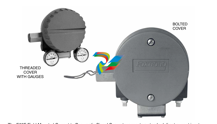
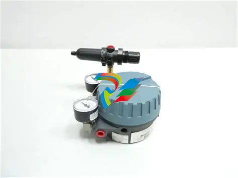
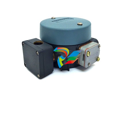 Foxboro E69F-TI2-J-R-S E69F Series Current-To-Pneumatic Signal Converter
 -
 Foxboro E69F-BI2-S Converter
 -
.jpg) Foxboro H92A049E0700 The host of the DCS control station
Foxboro H92A049E0700 The host of the DCS control station -
 Foxboro H90C9AA0117S Industrial computer workstation
 -
 Foxboro RH101AA High-performance industrial control module
 -
 Foxboro P0922YU FPS400-24 I/A Series Power supply
 -
.png) FOXBORO P0973LN Chassis-based managed switch with independent power supply
FOXBORO P0973LN Chassis-based managed switch with independent power supply -
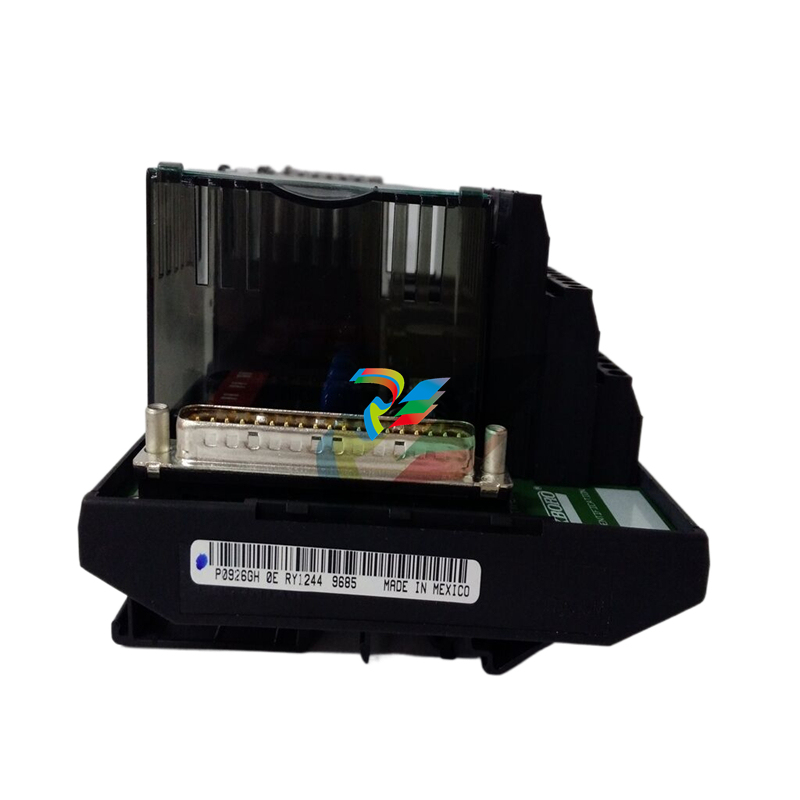
.jpg) FOXBORO P0926PA Input/output module
FOXBORO P0926PA Input/output module -
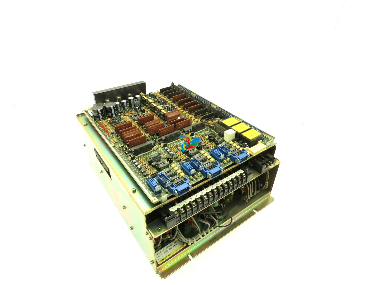 Fanuc A06B-6050-H402 3 AXIS ANALOG AC SERVO DRIVE
 -
.jpg) FOXBORO L0130AD L0130AE-0H Power module group
FOXBORO L0130AD L0130AE-0H Power module group -
_lVjBYb.jpg) FOXBORO 0399085B 0303440C+0303458A Combination Control Module
FOXBORO 0399085B 0303440C+0303458A Combination Control Module -
 FOXBORO SY-0399095E (SY-0303451D+SY-0303460E) Process control board
 -
.jpg) FOXBORO 0399071D 0303440C+0303443B Input/Output (I/O) Module
FOXBORO 0399071D 0303440C+0303443B Input/Output (I/O) Module -
.jpg) FOXBORO RH924UQ Redundant Controller module
FOXBORO RH924UQ Redundant Controller module -
 FFOXBORO E69F-TI2-S current pneumatic converter
 -
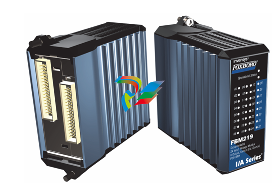 FOXBORO FBM219 RH916RH Discrete I/O Module
 -
 FOXBORO FBM227 P0927AC Module
 -
.jpg) FOXBORO 0399144 SY-0301059F SY-1025115C/SY-1025120E I/O module
FOXBORO 0399144 SY-0301059F SY-1025115C/SY-1025120E I/O module -
.jpg) FOXBORO SY-60399001R SY-60301001RB Industrial Control Module
FOXBORO SY-60399001R SY-60301001RB Industrial Control Module -
 FOXBORO 0399143 SY-0301060R SY-1025115C SY-1025120E Combined control board
 -
 FOXBORO 873EC-JIPFGZ electrodeless conductivity analyzer
 -
 FOXBORO P0916PH (High-density HART I/O Module)
 -
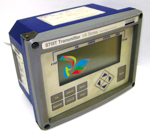 FOXBORO 870ITEC-AYFNZ-7 Intelligent Electrochemical Transmitters
 -
 FOXBORO Compact FBM240. Redundant with Readback, Discrete
 -
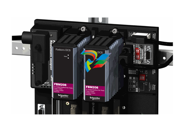 FOXBORO FBM208/b, Redundant with Readback, 0 to 20 mA I/O Module
 -
 FOXBORO FBM201e Analog Input (0 to 20 mA) Interface Modules
 -
.jpg) FOXBORO P0916WG Terminal cable
FOXBORO P0916WG Terminal cable -
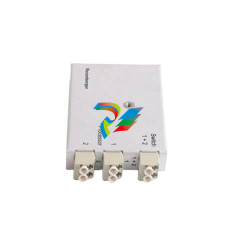 FOXBORO P0926MX 2-Port Splitter
 -
.jpg) FOXBORO AD908JQ High-Frequency Module
FOXBORO AD908JQ High-Frequency Module -
.jpg) FOXBORO AD916CC Processor module
FOXBORO AD916CC Processor module -
 Foxboro DCS FBM206 Pulse Input Module
 -
 FOXBORO FBM216 HART® Communication Redundant Input Interface Module
 -
 Foxboro p0903nu 1×8 unit sub-component module
 -
 Foxboro P0911SM Industrial control module
 -
 Foxboro CM902WM I/O module
 -
 Foxboro CM902WL Power module


