
GE Digital Energy D20 Analog Input Module
GE Digital Energy D20 Analog Input Module
Overview
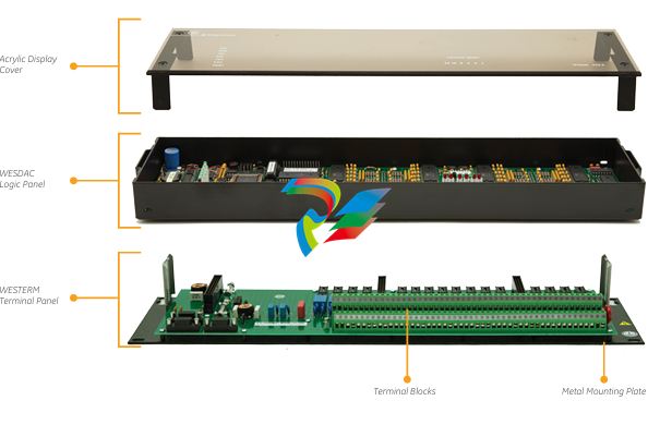
The D20 Analog module is composed of two detachable modules, WESTERM D20 A and WESDAC D20 A.
The bottom module, WESTERM D20 A, is where all field wirings are terminated. The top module, WESDAC
D20 A, processes the data acquired and communicates this to the main D20 processor, see Figure 2.
The WESTERM D20 A is the termination module for the WESDAC D20 A analog input module. All field,
I/O, and power terminations for the WESDAC D20 A are made on the WESTERM D20 A. Up to 32 analog
inputs can be accommodated on compression type terminations. Through the use of input adapter
modules, individual inputs can be configured for voltage or current. Voltage ranges currently accepted
are 1. 5 or 10 volt full scale unipolar or bipolar. Current inputs are sampled via a shunt resistor and
therefore almost any common current range can be accepted. A wetting source is supplied for current
loop inputs.

Capacitors and varistors are equipped to provide Surge Withstand Capability (SWC) as well as impulse
protection on all field inputs. Loop voltage for field transducers can be provided on an individual input
basis. The voltage source can be either the input to the WESDAC D20 A or an external source.
Two DB 9 connectors are provided to allow daisy chaining of the D.20 Link. This link provides the
communication channel over which the main D20 CPU processor, the WESDAC D20 M, can communicate
with the WESDAC D20 A. Power for the WESDAC D20 A is also provided over the same cable assembly.
The power is fused and filtered by passive components on the WESTERM D20 A.
A single DB 9 connector is provided for the WESMAINT D20 maintenance port. This port allows
communications between a VT 100 terminal or emulator, and the WESDAC D20 A. Module input data as
well as diagnostic information can be viewed over the maintenance port. The address jumper block for
the WESDAC D20 A is located on the WESTERM D20 A. The address on the jumper block corresponds to
the module’s address on the D.20 link.
The WESDAC D20 A is physically mounted on and electrically connected to the WESTERM D20 A through
three 40 pin connectors. The two modules are mounted on a 19 inch rack and all field terminations are
wired into the WESTERM D20 A.
Only passive components are mounted on the WESTERM D20 A leaving all the active components on the
WESDAC D20 A. This arrangement simplifies in field repair of the unit since the WESDAC D20 A can be
replaced without disturbing any of the field wiring.
Distributed I/O Architecture
The D20 Remote Terminal Unit (RTU) design is based on a distributed
processing architecture including real-time data acquisition and control
software. These I/O modules can be located close to the primary equipment
being monitored and controlled as they receive and send data back to the
master D20 main processor.
The I/O modules are intelligent modules that contain on-board
microprocessors and are configured as slave devices to the D20 main
processor. In the Figure 1 pictorial setup, specific I/O processing is distributed
throughout the D20 RTU to the appropriate I/O modules.
The I/O modules support two communication protocols: (1) DNP 3 protocol,
and (2) high speed, high-level data link controller (D.20 Link, HDLC) protocol.
The peripheral modules have serial communication ports and various types
of field connections.
The hardware construction of each remote I/O module type is similar (see
Figure 2.)
Data Processing
D20 I/O peripherals provide specialized processing and storing/buffering
functions for analog inputs/outputs by gathering data from field sources or
acting as an output unit to interface with field devices.
I/O processing provides flexible, reliable, robust operation and is configurable
on a per-point or per-system basis.
The D20A is capable of processing standard voltage and current inputs
continuously. It supports the following:
• Programmable Input Ranges: A programmable gain instrument amplifier
permits programming of voltage input ranges. Ranges are stored in RAM
on a per-point basis. (+/- 1. +/-5. +/- 10 V scale).
• Variable Scan Rate: Programmable scan rate from 17.2 to 20.5 ms (50/60
Hz) on a per module basis.
• 32 Differential Analog Inputs and eight internal references using
synchronous integrating-type analog-to-digital (A/D) converters.
• A/D Conversion provides excellent normal-mode rejection characteristics
while maintaining very good response times (approximately 550 ms total).
Termination Types
D20 Analog I/O module can be ordered with the following field termination
options:
| User name | Member Level | Quantity | Specification | Purchase Date |
|---|


-
 Hirschmann Industrial Ethernet Rail Switch RS20 Basic Family
 -
 GE Grid Solutions P40U Px40 USB Adaptor
 -
 ABB ontinuous Gas Analyzers AO2000 Series AO2040CU Ex Central Unit in Category 2G
 -
 ABB Advance Optima AO2000 Series Continuous gas analyzers Models AO2020. AO2040
 -
 Advance Optima Module Uras 14
 -
 SAACKE control optimization
 -
 SAACKE se@vis efficiency monitor
 -
 SAACKE se@vis pro
 -
 SAACKE se@vis eco
 -
 SAACKE se@vis compact
 -
 HIRSCHMANN Industrial ETHERNET Switch MICE MS20/MS30
 -
 HIRSCHMANN MICE Media modules
 -
 Kongsberg GL-10 Level Switch
 -
 B&R ACOPOSinverter P74 frequency converter
 -
 Beckhoff CX2020 | Basic CPU module (service phase)
 -
 Beckhoff CX1010 | Basic CPU module (service phase)
 -
 Beckhoff CX5120 | Embedded PC with Intel Atom® E3815
 -
 Beckhoff CP69xx-xxxx-0010 | Economy built-in Control Panel with DVI/USB Extended interface
 -
 Beckhoff CP29xx-0000 | Multi-touch built-in Control Panel with DVI/USB Extended interface
 -
 SAACKE Monoblock Rotary Cup Burner SKVJ-M
 -
 ABB Plantguard Fault Tolerant Technology Architecture and Software
 -
 OMRON H8PR-8/H8PR-8P H8PR-16/H8PR-16P H8PR-24/H8PR-24P Rotary Positioner
 -
 ABB PFSA107-Z42 DTU Stressometer Digital Transmission Unit
 -
 Nidec Mentor MP
 -
 IBA ibaNet-E
 -
 IBA FO Connection to Reflective Memory
 -
 IBA FO Connection to Siemens Systems
 -
 IBA Interface Cards For Fiber Optic Connections
 -
 IBA Field and Drive Buses
 -
 IBA ibaPADU-S Modular System
 -
 IBA ibaMAQS
 -
 STUCKE SYMAP®ARC
 -
 STUCKE SYMAP®R
 -
 STUCKE SYMAP®Compact
 -
 MOOG G123-825-001 BUFFER AMPLIFIER
 -
 Motorola MVME5100 Series VME Processor Modules
 -
 Motorola MVME162 Embedded Controller
 -
 HIMatrix Safety-Related Controller System Manual for the Modular Systems
 -
 Motorola MVME2400 Series VME Processor Module
 -
 Sieger System 57
 -
 KONGSBERG MRU product line continuation
 -
 Woodward easYgen-3100/3200 Genset Control for Multiple Unit Operation
 -
 Woodward MFR 300 Multifunction Relay / Measuring
 -
 ABB AX410, AX411, AX413, AX416, AX418, AX450, AX455 and AX456 Single and dual input analyzers for low level conductivity
 -
 ABB AX410, AX411, AX416, AX450 and AX455 Single and dual input analyzers
 -
 Woodward easYgen-1400 Technical Manual Genset Control
 -
 Woodward easYgen-400 Operation Manual Genset Control
 -
 Woodward High Output Digital Valve Positioner (DVP)DVP5000/DVP10000/DVP12000
 -
 Woodward High Output Digital Valve Positioner DVP5000 and DVP10000
 -
 Woodward TG611-13/-17 Overspeed Test Device Conversion Kit
 -
 Woodward MicroNet Safety Module (MSM)
 -
 Woodward 2301A Electronic Load Sharing and Speed Control 9905/9907 Series
 -
 Woodward-Service Bulletin 01671
 -
 UniOP eTOP40B 12.1” TFT color display
 -
 UniOP eTOP40 TFT Color display
 -
 UniOP eTOP33B 10.4” TFT color display
 -
 UniOP eTOP33C eTOP33-0050 Resistive touchscreen
 -
UniOP eTOP30. eTOP32 eTOP32-0050 Human-machine interface equipment
-
 UniOP eTOP20B and eTOP21B eTOP20B-0050
 -
 UniOP eTOP12 eTOP12-0050 Advanced human-machine interface equipment
 -
 UniOP eTOP11 eTOP11-0050 HMI
 -
 UniOP eTOP06C HMI
 -
 UniOP eTOP06 HMI
 -
 UniOP eTOP05EB eTOP05EB-DF45 HMI
 -
 UniOP eTOP05. eTOP05P Human-machine interface equipment
 -
 UniOP eTOP03 eTOP03-0046
 -
 UniOP eTOP507 507U2P1 eTOP Series 500 Human-Machine Interface
 -
 UniOP eTOP307
 -
 UniOP ETT-VGA Human-machine interface touch unit
 -
 UniOP ePAD32B, ePAD33B and ePAD33BT ePAD33B-0350
 -
 UniOP ePAD05 and ePAD06
 -
 UniOP CP02R-04 Human-machine interface
 -
 UniOP ERT-16 - Industrial PLC Workstation
 -
 UniOP ePAD03 and ePAD04
 -
 UNIOP EPALM10-DA71 state-of-the-art handheld HMI
 -
 Watlow SERIES CLS200 SPECIFICATION SHEET
 -
 Detailed Explanation of B&R Power Panel 300/400: The Core of Industrial Automation Control
 -
 YOKOGAWA Models ANB10S, ANB10D, ANR10S, ANR10D Node Units (for FIO)
 -
 Woodward ESDR 4 Current Differential Protection Relay
 -
 Woodward easYgen-3000 Genset Control for
 -
 Woodward CPC-II Current-to-Pressure Converter
 -
 Woodward 8290-189-EPG-installation-manual 8290-044
 -
 Woodward Product Change Notification 06946A
 -
 Woodward Product Change Notification 06912
 -
 Fisher™ 4660 High-Low Pressure Pilot
 -
 Flexible digital protection and control equipment SYMAP®
 -
 Woodward 723PLUS Digital Control
 -
 Woodward 505 Digital Controller For steam turbineses
 -
 Woodward 85018V2 505E Digital Governor for Extraction Steam Turbines
 -
Woodward 85018V1 Turbine Control Parameters
-
Woodward 26871 505 Enhanced Digital Control for Steam Turbines
-
 Woodward 03365 505E (Extraction / Admission)
 -
 KONGSBERG RMP420-Remote Multipurpose Input/Output
 -
 KONGSBERG RCU501 Remote Controller Unit
 -
 KONGSBERG RCU500 Remote Controller Unit
 -
 K-Gauge TOP KONGSBERG Tank Overfill Protection SystemFeatures
 -
 Kongsberg DPS112 DGNSS (DGPS/DGLONASS) sensor
 -
 Kongsberg d0000930-presafe-atex-report signed
 -
 HIMax TECHNICAL FACTS X Series
 -
 GE Multilin F650
 -
 GE MIF II - Legacy
 -
 GE PQM II Power QualIty Meter
 -
 Hydran 201Ti Mark IV Essential DGA monitoring for transformers
 -
 alstom AMS42/84 5B Amplifier SystemAmplifier Technology at its Best.
 -
 GE VMIVME-5576 Fiber-Optic Reflective Memory with Interrupts
 -
 GE Multilin 750/760 - Legacy Feeder Protection System
 -
 GE Fanuc Automation VMICPCI-7806 Specifications
 -
 VMIVME-7807 VME-7807RC* Intel® Pentium® M-Based VME SBC
 -
 GE Fanuc Automation VMIVME-7750 Specifications
 -
 FOXBORO Compact FBM240. Redundant with Readback, Discrete
 -
 FOXBORO FBM208/b, Redundant with Readback, 0 to 20 mA I/O Module
 -
 FOXBORO FBM201e Analog Input (0 to 20 mA) Interface Modules
 -
 Foxboro DCS FBM206 Pulse Input Module
 -
 FOXBORO FBM216 HART® Communication Redundant Input Interface Module
 -
 FOXBORO Z-Module Control Processor 270 (ZCP270)
 -
 FOXBORO Fieldbus Communications Module, FCM10Ef
 -
 FOXBORO Fieldbus Communications Module, FCM10E
 -
 Foxboro DCS Compact FBM241/c/d, Redundant, Discrete I/O Modules
 -
Foxboro FBM223 PROFIBUS-DP™ Communication Interface Module
-
 Foxboro DCS FBM204. 0 to 20 mAI/OModule
 -
Foxboro FBM239, Discrete 16DI/16DO Module
-
Foxboro FBM202 Thermocouple/mV Input Module
-
 Foxboro E69F Current-to-Pneumatic Signal Converter
 -
 EMERSON M-series Intrinsically Safe I/O
 -
 MVME6100 Series VMEbus Single-Board Computer
 -
 Configuration for AMS 6500 Protection Monitors
 -
 Ovation™ Controller Model OCR1100 (5X00481G04/5X00226G04)
 -
 ABB UCU-22, UCU-23 andUCU-24control units


