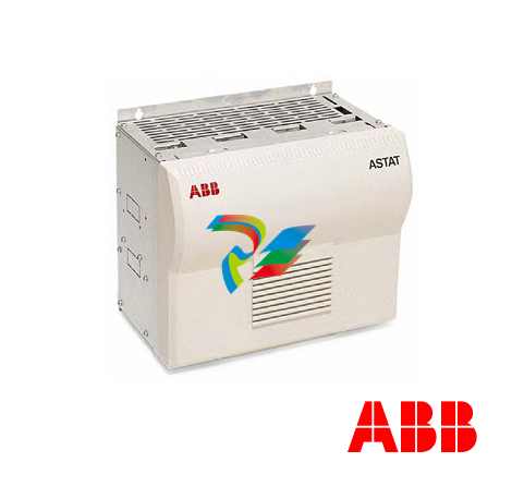
ABB ASTAT® Crane motion controller Version AST10_054
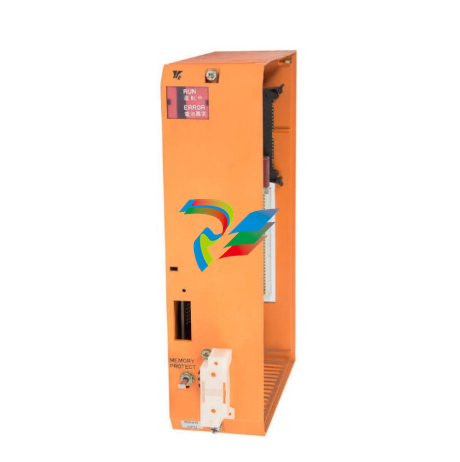
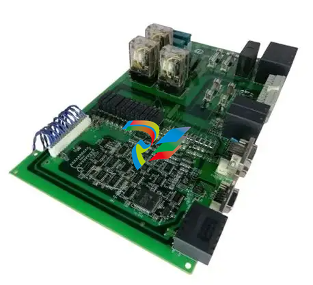
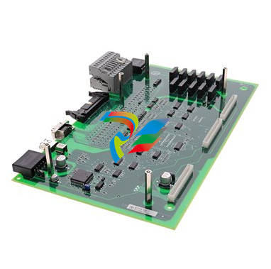
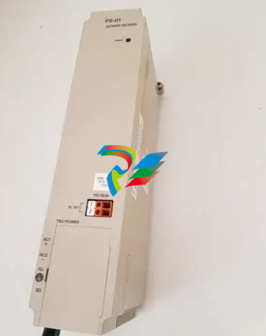
ASTAT system basics ASTAT® is a highly developed, well-proven system for speed controlled heavy-duty motors in cranes and other heavy industrial machinery. Designed for even the toughest environments ASTAT brings reliable, cost effective crane control into the computer age. Using leading edge computer technology, ASTAT now combines advanced control features with compre hensive information and data distribution to enhance performance at all levels. ASTAT is made especially for high utilisation, designed with higher-grade components and larger margins than normal industrial drives. The motor is the torque-producing device of an ASTAT Motion Control system. The electrical power is fed to the motor from the power bus through the DASD Thyristor Module. The DARA Control System Module controls the voltage of the DASD Thyristor modules. The DARA Control System Module controls the voltage and its phase sequence as well as selecting the best speed-torque characteristic for the motor based on desired and real speed. A tachometer, a pulse en coder or a DADT 100 Feedback Module measures the real speed. The desired speed comes from a DAPM Cabin I/O Module. For optimisation of torque-speed characteristic an external rotor resistor and sometimes a contactor are used. The ASTAT system is primary designed for loads that most of the time moves at full speed. In this normal state the speed control is replaced by full motor voltage. There are several options to the ASTAT Crane Motion Control program, below is shown a DASG line Over voltage protection Module.Inside each group mostly only a few parameters have to be modified for each installation while the others can be left as the Normal value suggested or from the company standard of the user. In most cases the majority of parameters can be left as they are. It is not only possible to set parameters. A large number of signals are available for daily supervision and maintenance support as well as for qualified troubleshooting and motion control optimisation. Signals can either be internal inside a group of functions or between different groups.How it all works ASTAT uses, like a car, two variables for the control: Stator control, corresponding to the accelerator of the car, and the Rotor control, corresponding to the gearbox. To continue this parallel, like a good driver, she will use the brake only in emergency situations and as a parking brake. Like in the modern car, the control system includes functions like a cruise control, the speed regulator, and automatic gearbox, the optimisation of rotor characteristic. Further more, with ASTAT the speed regulator can be disconnected, and the driver can control the motion directly as with the accelerator of her car.
Rotor control by optimising the resistance gives the motor the right characteristics The slip-ring motor torque is controlla ble at any speed by varying the external rotor resistance. Here the different speeds 92% and 57% up as well as 38% down are obtained with only varia tion of the resistance. This property has been used for many years for crane motors. When lowering with a slightly higher speed than the motors synchronous, in this example 107% of the synchronous, the motor will regenerate the energy back to the line in the most robust man ner. When the lowering speed is ap proaching the synchronous, the rotor resistor is minimised and the direction of torque changes electronically to act like a motor down. In the figure, this is shown by drawing the lowering load line, Td, for both plug braking and for regenerative lowering. For earlier generations of ASTAT controllers a compromise between the motors torque at lowest expected line voltage and lowest peak current at normal voltage was necessary. Load line This ASTAT generation has no need for ma nual adjustment, and considers with high frequency which is the best motor character istic at this voltage Target: Not more current than necessary. The number of rotor characteristics is se lected according to the duty. ASTAT supports 1 - 5 characteristics.


.png)


