
Foxboro FBM223 PROFIBUS-DP™ Communication Interface Module
FBM223 PROFIBUS-DP™ Communication Interface Module

The FBM223 PROFIBUS-DP™ Communication Interface Module provides an interface between
PROFIBUS-DP slave devices and the I/A Series® system.
FEATURES
Key features of the FBM223 module are:
Conforms to PROFIBUS-DP Fieldbus
specifications
Provides full support for all device variables and
diagnostic messages
Integrates PROFIBUS slave device data into an
I/A Series control database
The FBM223 and its associated termination
assembly (TA) are suitable for installation in
Class 1. Division 2 and Zone 2 locations.
OVERVIEW
The PROFIBUS-DP Communication Interface Module
(FBM223) provides an interface between
PROFIBUS-DP slave devices — such as motor
drives, I/O modules, and field I/O devices — and the
I/A Series system.
PROFIBUS is a vendor-independent, open fieldbus
standard for a wide range of applications in process
automation and manufacturing. Vendor
independence and openness are guaranteed by the
PROFIBUS Fieldbus standard EN 50170. which
specifies the functional, electrical, and mechanical
characteristics for a serial transmission bus.
Physical PROFIBUS-DP wiring is in accordance with
Electronic Industrial Association (EIA) standard RS
485.
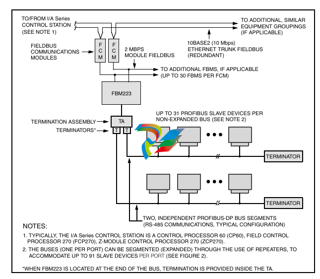
In addition to the general PROFIBUS-DP
configuration shown in Figure 1. several other
configurations are possible, including those using
repeaters and intrinsic safety protective devices.
Figure 2 shows how a bus can be expanded into
multiple segments through the use of repeaters, thus
providing support for a greater number of slave
devices.
FBM223 communicates with the PROFIBUS I/O
devices on a master/slave basis. As master, the
FBM223 initializes each data communication
exchange. The slave devices can only acknowledge
received messages, or send messages to the master
when requested to do so.
PROFIBUS-DP TECHNOLOGY
“DP” (in PROFIBUS-DP) represents the
communication profile that is most often used with
PROFIBUS — decentralized periphery. It is optimized
for speed, efficiency, and low connection cost, and is
designed especially for communication between
automation systems (such as the I/A Series control
system) and distributed field devices.
GSD FILES
A GSD file identifies a PROFIBUS-DP device. It
contains information specific to each device and
specifies parameters such as baud rates, timing
information and supported options such as
diagnostics and data length. A GSD file, provided by
the device manufacturer, is available for each device
type.
The data transmission method used with
PROFIBUS-DP is in accordance with EIA standard
RS-485. a proven serial communication technology
used in universal applications in process control and
manufacturing automation. Applications for RS-485
include all areas in which high transmission speed
and simple, inexpensive installation are required. The
physical communication medium consists of twisted
pair shielded copper cable containing a single
conductor pair. Active bus terminators, required at
either end of the bus or bus segment, typically exist
within the bus connectors or within the devices
themselves.
The I/A Series system uses the information in the
GSD file to set up communication to the slave
device. A configurator, available on the operator
station (UNIX® or Windows® based) allows the
importation of such files for establishing supported
options and for validating the values set by the user
NETWORK EXPANSION
Without the use of repeaters (non-expanded bus
configuration) up to 31 slave stations can exist on a
PROFIBUS-DP bus. Depending on the selected data
transfer rate, cabling distances up to 1200 m
(3960 ft) are possible without the use of repeaters
(see Table 1).
The use of repeaters provides for expansion of the
bus, allowing a greater number of slave devices per
FBM223 port, up to 91.
For a given system, with the use of repeaters the
maximum number of slave devices supported on an
FBM223 port is dependent on the amount of I/O that
is configured per device for access by the FBM223.
FBM CAPACITY
For the complete specification of number of devices
supported versus maximum I/O per device, refer to
the PROFIBUS-DP Communication Interface Module
(FBM223) User’s Guide (B0400FE).
From the I/A Series control station to which the
FBM223 is connected (refer to Figure 1), up to 100
connections per FBM223 port can be made to the
I/O data being accessed (read or written) by the
FBM223 over PROFIBUS.
A connection may be to:
An analog input or output value (integer or
floating point)
A string input or output
A single digital input or output value
Multiple (packed) digital input or output values
(packed in groups of up to 32 digital points per
connection).
Thus an I/A Series control station can access up to
100 analog I/O values, or 3200 digital I/O values, or a
combination of digital, analog, and string I/O, via
each of the two ports of the FBM223. The frequency
of access to FBM223 data by a control station may
be as fas
FIELDBUS COMMUNICATION
TERMINATION ASSEMBLY
The Fieldbus Communications Module (FCM) or the
Field Control Processor (FCP) interfaces to the
redundant 2 Mbps module Fieldbus used by the
FBMs. The FBM223 accepts communication from
either path (A or B) of the 2 Mbps Fieldbus — should
one path fail or be switched at the system level, the
-
 Hirschmann M1-8SFP Switche
 -
 Hirschmann Industrial Ethernet Ruggedized Switch MACH1000 Family
 -
 Basler Electric, Solid State Protective Relay, BE1-60
 -
BASLER ELECTRIC SR4A-2B15B3A Static Voltage Regulator
-
.png) BASLER ELECTRIC EXCITER DIODE MONITOR EDM-200
BASLER ELECTRIC EXCITER DIODE MONITOR EDM-200 -
.png) BASLER ELECTRIC DECS125-15-B2C5 DIGITAL EXCITATION CONTROL SYSTEM V 2.0.9
BASLER ELECTRIC DECS125-15-B2C5 DIGITAL EXCITATION CONTROL SYSTEM V 2.0.9 -
 BASLER ELECTRIC BE1-851 OVERCURRENT PROTECTION RELAY MECHANISM
 -
 Basler Electric BE1-51A / BE151A
 -
 Basler Electric BE1-40Q Loss of Excitation Relay
 -
 Basler Electric BE1-87G Variable Percentage Differential Relay
 -
 Basler Electric BE1-11 Protection System I5A3M2P2N0EA00
 -
 BASLER ELECTRIC DECS-200-1C Digital Excitation Control System
 -
 Basler Electric / Kohler BE1-11g Generator Protection Relay G5A3M2J2N0E000
 -
BASLER ELECTRIC DECS125-15 DIGITAL EXCITATION CONTROL SYSTEM
-
 BASLER ELECTRIC BE1-951 OverCurrent Protecton System
 -
Basler Electric DECS-200-1L Digital Excitation Control System
-
 Basler Electric DGC-2020HD-5NS1DNSBA Digital Genset Controller -
 -
 BASLER ELECTRIC BE1-81T1EE1WA0N1F / BE181T1EE1WA0N1F
 -
 BASLER ELECTRIC BE1-25M1EA6PN5R1F / BE125M1EA6PN5R1F
 -
 BASLER ELECTRIC DECS-250-LN1SN1N DIGITAL EXCITATION CONTROL SYSTEM
 -
Basler Electric DECS-250-CN2CN 1N Digital Excitation Control System Unit
-
 BASLER ELECTRIC DECS-300-C0N0 DIGITAL EXCITATION CONTROL SYSTEM
 -
 BASLER ELECTRIC BE1-87T-A1E-A1J-D0S1F / BE187TA1EA1JD0S1F
 -
BASLER ELECTRIC BE1-11-G6D1M0J2P0E000 Protection System
-
 BASLER ELECTRIC BE1-GPS100-E4N1H1N GENERATOR PROTECTION SYSTEM
 -
 Jaquet Relay card (Auxiliary module) FTV 3090 377Z-03985
 -
 Jaquet Trip Chain Control card FTBU 3034 377Z-05030
 -
 Jaquet with input card -E04 FTFU 3024 -E04 377Z-05855
 -
 Jaquet with input card -E03 FTFU 3024- E03 377Z-03983
 -
 Jaquet FTFU 3024- E02 377Z-03982 with input card -E02
 -
 Jaquet FTFU 3024-E01 377Z-03981 with input card -E01
 -
 Hirschmann RS20-2400T1T1SDAE Industrial Managed Ethernet Switch
 -
 Hirschmann BELDEN EAGLE30-04022O6TT999SCCV9HSE3F
 -
 Hirschmann MM3-2FXS2/2TX MICE Media Module
 -
 Hirschmann RS20-1600M2M2SDAPHC08.0.05 Industrial Managed Switch
 -
 Hirschmann OZD Profi 12M G12-1300 PRO Fieldbus Repeater
 -
 Hirschmann SPIDER 4TX/1FX-ST EEC Industrial Ethernet Switch
 -
 Hirschmann MM2-2FXM3/2TX1 MICE Media Module
 -
 Hirschmann RS20-2400M2M2SDAPHC09.0.14 Industrial Switch
 -
 Hirschmann RS20-0400M2M2SDAEHC07.1.05 OpenRail Switch
 -
 Hirschmann OZD Profi 12M G12-EEC Fieldbus Repeater
 -
 HIRSCHMANN MDA422-1/2-3.5c-23/46 sensor
 -
Hirschmann RS30-2402T1T1SDAUHC Managed Industrial Switch
-
 Hirschmann OZD GENIUS G12 Industrial Switche
 -
 Hirschmann OZD 485 G12-1300 PRO Fieldbus Repeater
 -
 Hirschmann MM2-2FXM2 MICE Media Module
 -
 Hirschmann RS20-1600S2T1SDAUHC Managed Industrial Switch
 -
 Hirschmann MS20-0800SAAEHH04.2.04 MICE Switch
 -
 Hirschmann SPIDER 4TX/1FX EEC Unmanaged Industrial Switch
 -
 HIRSCHMANN MS4128-L3P EEC Managed Industrial Ethernet Switch
 -
 HIRSCHMANN RS20-0400M2T1SDAPHC08.0.01 Managed Switch
 -
 ETEL EA-S0M-400-40/80A-0000-00 AccurET Modular Power Supply
 -
 ETEL EA-B0I-0-0-0000-00 Backplane Interface Board
 -
 ETEL EA-P2M-400-15/40A-0100-00 Position Controller
 -
ETEL EA-P2M-400-15/40A-0000-00 Position Controller
-
 ETEL EA-P2M-400-10/20A-0100-01 Position Controller
 -
 ETEL EA-P2M-400-10/20A-0000-01 Position Controller
 -
 ETEL EA-P2M-400-5/10A-0100-01 Position Controller
 -
 ETEL EA-P2M-048-2.5/5A-0000-01 Modular Position Controller
 -
 ETEL EA-S0M-300-40/80A-0000-00 Power Supply Module
 -
 ETEL EA-P2M-300-07/15A-0100-01 Position Controller
 -
 ETEL EA-P2M-300-07/15A-0000-01: Modular Position Controller
 -
 ETEL EA-P2M-300-4/7.5A-0100-01 Overview
 -
 Basler Electric MOC2. Motor Operated Potentiometer
 -
 Basler Electric BE1-11 RTD Module, Resistance Temperature Detector
 -
 Basler Electric RDP-110C, Remote Display Panel
 -
 Basler Electric VRM-2020. Voltage Regulation Module
 -
 Basler Electric IDP-1500. Interactive Display Panel
 -
 Basler Electric AEM-2020. Analog Expansion Module
 -
 Basler Electric IDP-2020. Interactive Display Panel
 -
 Basler Electric CEM-2020. Contact Expansion Module
 -
 Basler Electric CEM-125. Contact Expansion Module
 -
 Basler Electric BE2000E, Digital Voltage Regulator
 -
 Basler Electric SMC-150. Synchronous Motor Controller
 -
 Basler Electric AVC125-10. Voltage Regulator
 -
 Basler Electric BE1-25. Sync-Check Relay
 -
 Basler Electric DGC-2020ES, Digital Genset Controller
 -
 ETEL EA-P2M-400-5/10A-0000-01 Position Controller
 -
 Basler Electric BE1-64F, Ground Fault Relay
 -
 Basler Electric BE1-79M, Multi Shot Reclosing Relay
 -
 Basler Electric BE1-81O/U, Digital Frequency Relay
 -
 Basler Electric BE1-87B, High Impedance Bus Differential Relay
 -
 Basler Electric BE1-79A, Reclosing Relay
 -
 Basler Electric BE1-27. BE1-59. BE1-27/59. Voltage Relay
 -
 Basler Electric SMC-250. Synchronous Motor Controller
 -
 Basler Electric SGC-250N, Synchronous Generator Controller
 -
 Basler Electric SGC-250. Synchronous Generator Controller
 -
 Basler Electric BE1-50/51 Plug and Play and Retrofit Relays
 -
 Basler Electric DECS-2100. Digital Excitation Control System
 -
 Basler Electric DECS-250E, Digital Excitation Control System
 -
 Basler Electric BE1-700V, Voltage Only Digital Protective Relay
 -
 Basler Electric DECS-250. Digital Excitation Control System
 -
 Basler Electric DECS-450. Digital Excitation Control System
 -
 Basler Electric DECS-150. Digital Excitation Control System
 -
 Basler Electric ES-49. Temperature Relay
 -
 Basler Electric ES-81O/U, ES-81O,ES-81U Overfrequency Relay
 -
Basler Electric ES-74V, DC Voltage Sensing Relay
-
Basler Electric ES-27/59. Under/Overvoltage Relay
-
 Basler Electric ES-27. Undervoltage Relay
 -
 Basler Electric ES-25. Sync-Check Relay
 -
 Basler Electric ES-47, ES-47N Phase Sequence Relay
 -
Basler Electric ES-37.ES-37/51 Undercurrent Relay
-
 Basler Electric ES-32. Reverse Power Relay
 -
Basler Electric ES-59. Overvoltage Relay
-
 Basler Electric ES-55. Power Factor Relay
 -
 Basler Electric DGC-2020HD, Digital Genset Controller
 -
 Basler Electric BE1-FLEX, Protection, Automation, and Control System
 -
 Schneider GUTOR OC0935 Power Factor Sampling Board
 -
 Schneider GUTOR OC0922 Analog Signal Isolation Board
 -
 Schneider GUTOR OC0908 Battery Voltage Detection Board
 -
Schneider GUTOR OC0947 Temperature / IGBT Sampling Board
-
 Schneider GUTOR OP2601 Communication Expansion Board
 -
 Schneider Electric GUTOR OP2312 bypass control board
 -
 Schneider Electric GUTOR OP2130 Cooling Fan Monitoring & Control Board
 -
 Schneider Electric GUTOR OP2010 Battery Test Board / Battery Management Diagnostic Card
 -
Schneider Electric GUTOR OP2552 Three-phase Power Connection Board Assembly
-
 Schneider Electric GUTOR OP1922A Parallel Control Board / Load-Sharing Synchronization Module
 -
 Schneider Electric GUTOR OP6290B Inverter Feedback Acquisition Board / Signal Scaling Module
 -
Schneider GUTOR OP6280 Basic Signal Board
-
Schneider Electric GUTOR OP2456 / OP2456B Main control board
-
 Schneider Electric GUTOR OP2452 Power Plug-in Panel
 -
 Schneider Electric GUTOR OP2450 Parallel Communication Board
 -
Schneider Electric GUTOR OP2406 Interface Fuse Monitoring Board
-
 Schneider Electric GUTOR OC0919 High-Power Semiconductor Module
 -
 Schneider Electric GUTOR OP6281A System Logic Interface Board
 -
 Schneider Electric GUTOR OP6285A Power Signal Acquisition Board
 -
 Schneider Electric GUTOR OP2438 Fan Monitor & Drive Protection Board
 -
Schneider Electric GUTOR OP2446 Main Control CPU Board


