
Woodward High Output DVP, 10KW TB Input/Output 8200-536
High Output DVP, 10KW TB Input/Output 8200-536
High Output DVP, 10KW
TB Input/Output
8200-536
TB Input/Output, SIL Certified
8200-545
TB Input/Output, Servo Interface Module (SIM)
8200-586
The DVP device may be controlled via CAN communication. There are three possible CAN modes:
1. CANopen single with or without analog backup
2. CANopen dual
3. CANopen virtual
1. The CANopen single with or without backup:
This mode uses CAN port 1 for communication. Optionally, it is possible to configure (by CAN
communication) the analog input as a backup signal. By default, the analog input is a backup signal.
(See analog input section for how to interface and setup an analog input.)
2. CANopen Dual:
This mode uses CAN port 1 and CAN port 2. If the two ports are working correctly, information
received from CAN port 1 is used. If communication by CAN port 1 is not possible any more (detected
by communication time out), CAN port 2 is used for communication.
3. CANopen Virtual:
This mode is used when two DVPs are linked together to control more than one actuator or valve. This
is used for Dual Redundant DVP Operation.
The CAN communication baud rate can be selected. The possible options are:
• 125 kbps
• 250 kbps
• 500 kbps
Per CiA DS-102 Standard, the following are the recommended maximum cable lengths. Differences in the
baud rate and the cable length affect the number of units that can be put onto a network.
If CAN port 1 is used, see Figure 3-13 of the CAN port interface. See the Analog Input section above for
the analog interface diagram when CAN is used with an Analog Input backup.
Pins 29 and 30 are the termination jumper. Connecting these two pins with a short wire on the connector
will enable an internal 120 Ω resistor between CAN high and CAN low wire.
Pins 31 and Pin 32 are the CAN High and CAN low wires typically found on a CAN system.
Pins 33 and 34 are two additional CAN high and CAN low pins. These can be used to daisy chain the
CANbus to the next device, without the need for a junction box.
Pin 35 is the CAN ground. The DVP side of the CAN link is galvanically isolated from the DVP, ground,
and system common. Therefore, we need to connect the isolated ground to the ground of the user
control.
Pin 36 is used to terminate the CAN wiring shield.
When using dual can communication mode, there are two identical communication ports. Port 1 and Port 2 are
wired identically. For description, see Port 1.
Table 3-16. Dual CAN Communication Wiring Specifications
Pin Number Function
29 CAN 1 Termination jumper
30 CAN 1 Termination jumper
31 CAN 1 High in
32 CAN 1 Low in
33 CAN 1 High out
34 CAN 1 Low out
35 CAN 1 ISO GND
36 CAN 1 Shield
37 CAN 2 Termination jumper
38 CAN 2 Termination jumper
39 CAN 2 High in
40 CAN 2 Low in
41 CAN 2 High out
42 CAN 2 Low out
43 CAN 2 ISO GND
44 CAN 2 Shield
See Appendix A for more information on CANopen communications.
3.14.1 CAN Node ID Selection
When using CANopen communications, it is necessary to set the CAN Node ID to a unique value to
ensure that the DVP responds to commands intended for the appropriate device. There are two methods
for setting this value— software or hardware/wiring. The method is defaulted to a predetermined
configuration based on the DVP part number but can be changed using the Service Tool (see manual
26912). With the software option, the node ID setting is a user-defined value set in software. The
hardware/wiring (also referred to as harness coding) option uses discrete inputs to select an index which
sets the node ID value. The index is determined by the power-up state of the discrete inputs. Note that
the discrete input condition is based on open or closed state at power-up, ignoring the active high/low
configuration. Changes to any Node ID-related software settings require a power cycle to take effect.
The discrete input CAN ID selection has three different options. The index can be based on two, three, or
four discrete inputs, allowing three, seven, or 15 valid preprogrammed settings. This selection method is
set using the Service Tool as part of the CAN demand configuration. Tables 3-17. 3-18. and 3-19 identify
the selected index based on the configured selection method.
Definitions:
• Discrete Input 5: connection between terminal 24 and GROUND
• Discrete Input 4: connection between terminal 23 and GROUND
• Discrete Input 3: connection between terminal 22 and GROUND
• Discrete Input 2: connection between terminal 21 and GROUND
• Discrete Input 1: connection between terminal 20 and GROUND
• (GROUND can be any terminal 25. 26 or 27)
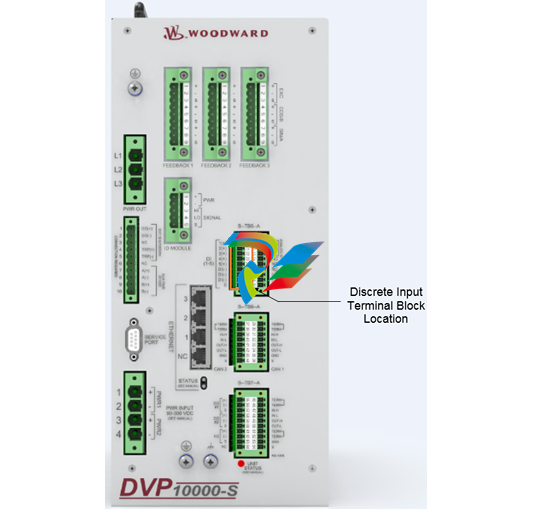
3.14.2 Instructions for Use of CAN ID Terminal Blocks
When using the harness coding method (as described in Section 3.14.1), it is necessary to install a
jumper terminal block within each positioner during initial installation. This terminal block configures each
positioner for proper communication with its assigned primary or secondary CAN Open Network. The
installation of this terminal block must be performed before attempting power-up or communications
across the CAN Open Network. Until this process is complete, the positioners will not communicate with
the networks. Install jumpers based on the CAN ID Node Selection and using the information from the
appropriate table (3-17. 3-18. and/or 3-19).
Proper installation of the CAN ID Terminal Blocks is performed by the following steps:
1. Ensure that there is no power being applied to the DVPs.
2. Determine which DVP will be connected to the Primary CAN Network, and which will be connected to
the Secondary CAN Network.
3. Create the appropriate CAN ID Terminal Block associated with each CAN Network.
| User name | Member Level | Quantity | Specification | Purchase Date |
|---|


-
 Basler Electric DECS-200 Digital Excitation Control System
 -
 Basler Electric GENERATOR PROTECTION SYSTEM BE1-GPS100
 -
 Jaquet FT3000 Speed measurement system
 -
 Hirschmann Industrial Ethernet Ruggedized Switch MACH1000 Family
 -
 Basler Electric BESTCOMSPlus®
 -
 ETEL AccurET MODULAR 300 EA-P2M-300-xxxxxA controller
 -
 Basler Electric ES Series Protection Relays
 -
 ABB Multifunction Protection and Switchbay Control Unit REF542plus
 -
 EMERSON AMS 2140 Machinery Health Analyzer
 -
 Hirschmann Industrial Ethernet Rail Switch RS20 Basic Family
 -
 GE Grid Solutions P40U Px40 USB Adaptor
 -
 ABB ontinuous Gas Analyzers AO2000 Series AO2040CU Ex Central Unit in Category 2G
 -
 ABB Advance Optima AO2000 Series Continuous gas analyzers Models AO2020. AO2040
 -
 Advance Optima Module Uras 14
 -
 SAACKE control optimization
 -
 SAACKE se@vis efficiency monitor
 -
 SAACKE se@vis pro
 -
 SAACKE se@vis eco
 -
 SAACKE se@vis compact
 -
 HIRSCHMANN Industrial ETHERNET Switch MICE MS20/MS30
 -
 HIRSCHMANN MICE Media modules
 -
 Kongsberg GL-10 Level Switch
 -
 B&R ACOPOSinverter P74 frequency converter
 -
 Beckhoff CX2020 | Basic CPU module (service phase)
 -
 Beckhoff CX1010 | Basic CPU module (service phase)
 -
 Beckhoff CX5120 | Embedded PC with Intel Atom® E3815
 -
 Beckhoff CP69xx-xxxx-0010 | Economy built-in Control Panel with DVI/USB Extended interface
 -
 Beckhoff CP29xx-0000 | Multi-touch built-in Control Panel with DVI/USB Extended interface
 -
 SAACKE Monoblock Rotary Cup Burner SKVJ-M
 -
 ABB Plantguard Fault Tolerant Technology Architecture and Software
 -
 OMRON H8PR-8/H8PR-8P H8PR-16/H8PR-16P H8PR-24/H8PR-24P Rotary Positioner
 -
 ABB PFSA107-Z42 DTU Stressometer Digital Transmission Unit
 -
 Nidec Mentor MP
 -
 IBA ibaNet-E
 -
 IBA FO Connection to Reflective Memory
 -
 IBA FO Connection to Siemens Systems
 -
 IBA Interface Cards For Fiber Optic Connections
 -
 IBA Field and Drive Buses
 -
 IBA ibaPADU-S Modular System
 -
 IBA ibaMAQS
 -
 STUCKE SYMAP®ARC
 -
 STUCKE SYMAP®R
 -
 STUCKE SYMAP®Compact
 -
 MOOG G123-825-001 BUFFER AMPLIFIER
 -
 Motorola MVME5100 Series VME Processor Modules
 -
 Motorola MVME162 Embedded Controller
 -
 HIMatrix Safety-Related Controller System Manual for the Modular Systems
 -
 Motorola MVME2400 Series VME Processor Module
 -
 Sieger System 57
 -
 KONGSBERG MRU product line continuation
 -
 Woodward easYgen-3100/3200 Genset Control for Multiple Unit Operation
 -
 Woodward MFR 300 Multifunction Relay / Measuring
 -
 ABB AX410, AX411, AX413, AX416, AX418, AX450, AX455 and AX456 Single and dual input analyzers for low level conductivity
 -
 ABB AX410, AX411, AX416, AX450 and AX455 Single and dual input analyzers
 -
 Woodward easYgen-1400 Technical Manual Genset Control
 -
 Woodward easYgen-400 Operation Manual Genset Control
 -
 Woodward High Output Digital Valve Positioner (DVP)DVP5000/DVP10000/DVP12000
 -
 Woodward High Output Digital Valve Positioner DVP5000 and DVP10000
 -
 Woodward TG611-13/-17 Overspeed Test Device Conversion Kit
 -
 Woodward MicroNet Safety Module (MSM)
 -
 Woodward 2301A Electronic Load Sharing and Speed Control 9905/9907 Series
 -
 Woodward-Service Bulletin 01671
 -
 UniOP eTOP40B 12.1” TFT color display
 -
 UniOP eTOP40 TFT Color display
 -
 UniOP eTOP33B 10.4” TFT color display
 -
 UniOP eTOP33C eTOP33-0050 Resistive touchscreen
 -
UniOP eTOP30. eTOP32 eTOP32-0050 Human-machine interface equipment
-
 UniOP eTOP20B and eTOP21B eTOP20B-0050
 -
 UniOP eTOP12 eTOP12-0050 Advanced human-machine interface equipment
 -
 UniOP eTOP11 eTOP11-0050 HMI
 -
 UniOP eTOP06C HMI
 -
 UniOP eTOP06 HMI
 -
 UniOP eTOP05EB eTOP05EB-DF45 HMI
 -
 UniOP eTOP05. eTOP05P Human-machine interface equipment
 -
 UniOP eTOP03 eTOP03-0046
 -
 UniOP eTOP507 507U2P1 eTOP Series 500 Human-Machine Interface
 -
 UniOP eTOP307
 -
 UniOP ETT-VGA Human-machine interface touch unit
 -
 UniOP ePAD32B, ePAD33B and ePAD33BT ePAD33B-0350
 -
 UniOP ePAD05 and ePAD06
 -
 UniOP CP02R-04 Human-machine interface
 -
 UniOP ERT-16 - Industrial PLC Workstation
 -
 UniOP ePAD03 and ePAD04
 -
 UNIOP EPALM10-DA71 state-of-the-art handheld HMI
 -
 Watlow SERIES CLS200 SPECIFICATION SHEET
 -
 Detailed Explanation of B&R Power Panel 300/400: The Core of Industrial Automation Control
 -
 YOKOGAWA Models ANB10S, ANB10D, ANR10S, ANR10D Node Units (for FIO)
 -
 Woodward ESDR 4 Current Differential Protection Relay
 -
 Woodward easYgen-3000 Genset Control for
 -
 Woodward CPC-II Current-to-Pressure Converter
 -
 Woodward 8290-189-EPG-installation-manual 8290-044
 -
 Woodward Product Change Notification 06946A
 -
 Woodward Product Change Notification 06912
 -
 Fisher™ 4660 High-Low Pressure Pilot
 -
 Flexible digital protection and control equipment SYMAP®
 -
 Woodward 723PLUS Digital Control
 -
 Woodward 505 Digital Controller For steam turbineses
 -
 Woodward 85018V2 505E Digital Governor for Extraction Steam Turbines
 -
Woodward 85018V1 Turbine Control Parameters
-
Woodward 26871 505 Enhanced Digital Control for Steam Turbines
-
 Woodward 03365 505E (Extraction / Admission)
 -
 KONGSBERG RMP420-Remote Multipurpose Input/Output
 -
 KONGSBERG RCU501 Remote Controller Unit
 -
 KONGSBERG RCU500 Remote Controller Unit
 -
 K-Gauge TOP KONGSBERG Tank Overfill Protection SystemFeatures
 -
 Kongsberg DPS112 DGNSS (DGPS/DGLONASS) sensor
 -
 Kongsberg d0000930-presafe-atex-report signed
 -
 HIMax TECHNICAL FACTS X Series
 -
 GE Multilin F650
 -
 GE MIF II - Legacy
 -
 GE PQM II Power QualIty Meter
 -
 Hydran 201Ti Mark IV Essential DGA monitoring for transformers
 -
 alstom AMS42/84 5B Amplifier SystemAmplifier Technology at its Best.
 -
 GE VMIVME-5576 Fiber-Optic Reflective Memory with Interrupts
 -
 GE Multilin 750/760 - Legacy Feeder Protection System
 -
 GE Fanuc Automation VMICPCI-7806 Specifications
 -
 VMIVME-7807 VME-7807RC* Intel® Pentium® M-Based VME SBC
 -
 GE Fanuc Automation VMIVME-7750 Specifications
 -
 FOXBORO Compact FBM240. Redundant with Readback, Discrete
 -
 FOXBORO FBM208/b, Redundant with Readback, 0 to 20 mA I/O Module
 -
 FOXBORO FBM201e Analog Input (0 to 20 mA) Interface Modules
 -
 Foxboro DCS FBM206 Pulse Input Module
 -
 FOXBORO FBM216 HART® Communication Redundant Input Interface Module
 -
 FOXBORO Z-Module Control Processor 270 (ZCP270)
 -
 FOXBORO Fieldbus Communications Module, FCM10Ef
 -
 FOXBORO Fieldbus Communications Module, FCM10E
 -
 Foxboro DCS Compact FBM241/c/d, Redundant, Discrete I/O Modules
 -
Foxboro FBM223 PROFIBUS-DP™ Communication Interface Module


