
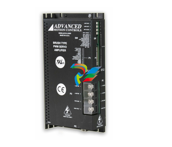
ADVANCEDMOTION CONTROLS Analog Servo Drive 120A10
ADVANCEDMOTION CONTROLS Analog Servo Drive 120A10
The 120A10 PWM servo drive is designed to drive
brush type DC motors at a high switching frequency.
A single red/green LED indicates operating status. The
drive is fully protected against over-voltage, under
voltage, over-current, over-heating and short-circuits
across motor, ground and power leads. Furthermore,
the drive can interface with digital controllers or be
used stand-alone and requires only a single
unregulated DC power supply. Loop gain, current
limit, input gain and offset can be adjusted using 14
turn potentiometers. The offset adjusting
potentiometer can also be used as an on-board input
signal for testing purposes.
See Part Numbering Information on last page of
datasheet for additional ordering options. The
hardware installation manual for the analog drive
family is available for download at www.a-m-c.com.
Optical Isolation Between High & Low Power
Signals
Four Quadrant Regenerative Operation
DIP Switch Selectable Modes
Differential Input Command
Digital Fault Output Monitor
On-Board Test Potentiometer
Offset Adjustment Potentiometer
Adjustable Input Gain
DIP Switch Selectable Tuning
Drive Status LED
Directional Inhibit Inputs for Limit Switches
MODES OF OPERATION
Current
Voltage
IR Compensation
Velocity
COMMAND SOURCE
±10 V Analog
FEEDBACK SUPPORTED
Tachometer (±60 VDC)
COMPLIANCES & AGENCY APPROVALS
UL
cUL
CE Class A (LVD)
CE Class A (EMC)
RoHS II
 Tuning With Through-hole Components
In general, the drive will not need to be further tuned with through-hole components. However, for applications requiring more
precise tuning than what is offered by the potentiometers and dipswitches, the drive can be manually modified with through-hole
resistors and capacitors as denoted in the above table. By default, the through-hole locations are not populated when the drive is
shipped. Before attempting to add through-hole components to the board, consult the section on loop tuning in the installation
notes on the manufacturer’s website. Some general rules of thumb to follow when adding through-hole components are:
• A larger resistor value will increase the proportional gain, and therefore create a faster response time.
• A larger capacitor value will increase the integration time, and therefore create a slower response time.
Proper tuning using the through-hole components will require careful observation of the loop response on a digital oscilloscope to
find the optimal through-hole component values for the specific application.
IR Compensation Notes
For applications that will use IR Compensation mode, a resistor can be added to the location named in the table above. The
combination of the added resistor and correct dipswitch settings will configure the amplifier for IR Compensation mode. While in
IR Compensation mode, the amplifier will adjust the duty cycle to compensate for changes in the output current. Consult the
amplifier’s functional block diagram and the manufacturer’s website for more information.
Tachometer Gain
Some applications may require an increase in the gain of the tachometer input signal. This occurrence will be most common in
designs where the tachometer input has a low voltage to RPM scaling ratio. The drive offers a through-hole location listed in the
above table where a resistor can be added to increase the tachometer gain. Use the drive’s block diagram to determine an
appropriate resistor value.
-
 Hirschmann M1-8SFP Switche
 -
 Hirschmann Industrial Ethernet Ruggedized Switch MACH1000 Family
 -
 Basler Electric, Solid State Protective Relay, BE1-60
 -
BASLER ELECTRIC SR4A-2B15B3A Static Voltage Regulator
-
.png) BASLER ELECTRIC EXCITER DIODE MONITOR EDM-200
BASLER ELECTRIC EXCITER DIODE MONITOR EDM-200 -
.png) BASLER ELECTRIC DECS125-15-B2C5 DIGITAL EXCITATION CONTROL SYSTEM V 2.0.9
BASLER ELECTRIC DECS125-15-B2C5 DIGITAL EXCITATION CONTROL SYSTEM V 2.0.9 -
 BASLER ELECTRIC BE1-851 OVERCURRENT PROTECTION RELAY MECHANISM
 -
 Basler Electric BE1-51A / BE151A
 -
 Basler Electric BE1-40Q Loss of Excitation Relay
 -
 Basler Electric BE1-87G Variable Percentage Differential Relay
 -
 Basler Electric BE1-11 Protection System I5A3M2P2N0EA00
 -
 BASLER ELECTRIC DECS-200-1C Digital Excitation Control System
 -
 Basler Electric / Kohler BE1-11g Generator Protection Relay G5A3M2J2N0E000
 -
BASLER ELECTRIC DECS125-15 DIGITAL EXCITATION CONTROL SYSTEM
-
 BASLER ELECTRIC BE1-951 OverCurrent Protecton System
 -
Basler Electric DECS-200-1L Digital Excitation Control System
-
 Basler Electric DGC-2020HD-5NS1DNSBA Digital Genset Controller -
 -
 BASLER ELECTRIC BE1-81T1EE1WA0N1F / BE181T1EE1WA0N1F
 -
 BASLER ELECTRIC BE1-25M1EA6PN5R1F / BE125M1EA6PN5R1F
 -
 BASLER ELECTRIC DECS-250-LN1SN1N DIGITAL EXCITATION CONTROL SYSTEM
 -
Basler Electric DECS-250-CN2CN 1N Digital Excitation Control System Unit
-
 BASLER ELECTRIC DECS-300-C0N0 DIGITAL EXCITATION CONTROL SYSTEM
 -
 BASLER ELECTRIC BE1-87T-A1E-A1J-D0S1F / BE187TA1EA1JD0S1F
 -
BASLER ELECTRIC BE1-11-G6D1M0J2P0E000 Protection System
-
 BASLER ELECTRIC BE1-GPS100-E4N1H1N GENERATOR PROTECTION SYSTEM
 -
 Jaquet Relay card (Auxiliary module) FTV 3090 377Z-03985
 -
 Jaquet Trip Chain Control card FTBU 3034 377Z-05030
 -
 Jaquet with input card -E04 FTFU 3024 -E04 377Z-05855
 -
 Jaquet with input card -E03 FTFU 3024- E03 377Z-03983
 -
 Jaquet FTFU 3024- E02 377Z-03982 with input card -E02
 -
 Jaquet FTFU 3024-E01 377Z-03981 with input card -E01
 -
 Hirschmann RS20-2400T1T1SDAE Industrial Managed Ethernet Switch
 -
 Hirschmann BELDEN EAGLE30-04022O6TT999SCCV9HSE3F
 -
 Hirschmann MM3-2FXS2/2TX MICE Media Module
 -
 Hirschmann RS20-1600M2M2SDAPHC08.0.05 Industrial Managed Switch
 -
 Hirschmann OZD Profi 12M G12-1300 PRO Fieldbus Repeater
 -
 Hirschmann SPIDER 4TX/1FX-ST EEC Industrial Ethernet Switch
 -
 Hirschmann MM2-2FXM3/2TX1 MICE Media Module
 -
 Hirschmann RS20-2400M2M2SDAPHC09.0.14 Industrial Switch
 -
 Hirschmann RS20-0400M2M2SDAEHC07.1.05 OpenRail Switch
 -
 Hirschmann OZD Profi 12M G12-EEC Fieldbus Repeater
 -
 HIRSCHMANN MDA422-1/2-3.5c-23/46 sensor
 -
Hirschmann RS30-2402T1T1SDAUHC Managed Industrial Switch
-
 Hirschmann OZD GENIUS G12 Industrial Switche
 -
 Hirschmann OZD 485 G12-1300 PRO Fieldbus Repeater
 -
 Hirschmann MM2-2FXM2 MICE Media Module
 -
 Hirschmann RS20-1600S2T1SDAUHC Managed Industrial Switch
 -
 Hirschmann MS20-0800SAAEHH04.2.04 MICE Switch
 -
 Hirschmann SPIDER 4TX/1FX EEC Unmanaged Industrial Switch
 -
 HIRSCHMANN MS4128-L3P EEC Managed Industrial Ethernet Switch
 -
 HIRSCHMANN RS20-0400M2T1SDAPHC08.0.01 Managed Switch
 -
 ETEL EA-S0M-400-40/80A-0000-00 AccurET Modular Power Supply
 -
 ETEL EA-B0I-0-0-0000-00 Backplane Interface Board
 -
 ETEL EA-P2M-400-15/40A-0100-00 Position Controller
 -
ETEL EA-P2M-400-15/40A-0000-00 Position Controller
-
 ETEL EA-P2M-400-10/20A-0100-01 Position Controller
 -
 ETEL EA-P2M-400-10/20A-0000-01 Position Controller
 -
 ETEL EA-P2M-400-5/10A-0100-01 Position Controller
 -
 ETEL EA-P2M-048-2.5/5A-0000-01 Modular Position Controller
 -
 ETEL EA-S0M-300-40/80A-0000-00 Power Supply Module
 -
 ETEL EA-P2M-300-07/15A-0100-01 Position Controller
 -
 ETEL EA-P2M-300-07/15A-0000-01: Modular Position Controller
 -
 ETEL EA-P2M-300-4/7.5A-0100-01 Overview
 -
 Basler Electric MOC2. Motor Operated Potentiometer
 -
 Basler Electric BE1-11 RTD Module, Resistance Temperature Detector
 -
 Basler Electric RDP-110C, Remote Display Panel
 -
 Basler Electric VRM-2020. Voltage Regulation Module
 -
 Basler Electric IDP-1500. Interactive Display Panel
 -
 Basler Electric AEM-2020. Analog Expansion Module
 -
 Basler Electric IDP-2020. Interactive Display Panel
 -
 Basler Electric CEM-2020. Contact Expansion Module
 -
 Basler Electric CEM-125. Contact Expansion Module
 -
 Basler Electric BE2000E, Digital Voltage Regulator
 -
 Basler Electric SMC-150. Synchronous Motor Controller
 -
 Basler Electric AVC125-10. Voltage Regulator
 -
 Basler Electric BE1-25. Sync-Check Relay
 -
 Basler Electric DGC-2020ES, Digital Genset Controller
 -
 ETEL EA-P2M-400-5/10A-0000-01 Position Controller
 -
 Basler Electric BE1-64F, Ground Fault Relay
 -
 Basler Electric BE1-79M, Multi Shot Reclosing Relay
 -
 Basler Electric BE1-81O/U, Digital Frequency Relay
 -
 Basler Electric BE1-87B, High Impedance Bus Differential Relay
 -
 Basler Electric BE1-79A, Reclosing Relay
 -
 Basler Electric BE1-27. BE1-59. BE1-27/59. Voltage Relay
 -
 Basler Electric SMC-250. Synchronous Motor Controller
 -
 Basler Electric SGC-250N, Synchronous Generator Controller
 -
 Basler Electric SGC-250. Synchronous Generator Controller
 -
 Basler Electric BE1-50/51 Plug and Play and Retrofit Relays
 -
 Basler Electric DECS-2100. Digital Excitation Control System
 -
 Basler Electric DECS-250E, Digital Excitation Control System
 -
 Basler Electric BE1-700V, Voltage Only Digital Protective Relay
 -
 Basler Electric DECS-250. Digital Excitation Control System
 -
 Basler Electric DECS-450. Digital Excitation Control System
 -
 Basler Electric DECS-150. Digital Excitation Control System
 -
 Basler Electric ES-49. Temperature Relay
 -
 Basler Electric ES-81O/U, ES-81O,ES-81U Overfrequency Relay
 -
Basler Electric ES-74V, DC Voltage Sensing Relay
-
Basler Electric ES-27/59. Under/Overvoltage Relay
-
 Basler Electric ES-27. Undervoltage Relay
 -
 Basler Electric ES-25. Sync-Check Relay
 -
 Basler Electric ES-47, ES-47N Phase Sequence Relay
 -
Basler Electric ES-37.ES-37/51 Undercurrent Relay
-
 Basler Electric ES-32. Reverse Power Relay
 -
Basler Electric ES-59. Overvoltage Relay
-
 Basler Electric ES-55. Power Factor Relay
 -
 Basler Electric DGC-2020HD, Digital Genset Controller
 -
 Basler Electric BE1-FLEX, Protection, Automation, and Control System
 -
 Schneider GUTOR OC0935 Power Factor Sampling Board
 -
 Schneider GUTOR OC0922 Analog Signal Isolation Board
 -
 Schneider GUTOR OC0908 Battery Voltage Detection Board
 -
Schneider GUTOR OC0947 Temperature / IGBT Sampling Board
-
 Schneider GUTOR OP2601 Communication Expansion Board
 -
 Schneider Electric GUTOR OP2312 bypass control board
 -
 Schneider Electric GUTOR OP2130 Cooling Fan Monitoring & Control Board
 -
 Schneider Electric GUTOR OP2010 Battery Test Board / Battery Management Diagnostic Card
 -
Schneider Electric GUTOR OP2552 Three-phase Power Connection Board Assembly
-
 Schneider Electric GUTOR OP1922A Parallel Control Board / Load-Sharing Synchronization Module
 -
 Schneider Electric GUTOR OP6290B Inverter Feedback Acquisition Board / Signal Scaling Module
 -
Schneider GUTOR OP6280 Basic Signal Board
-
Schneider Electric GUTOR OP2456 / OP2456B Main control board
-
 Schneider Electric GUTOR OP2452 Power Plug-in Panel
 -
 Schneider Electric GUTOR OP2450 Parallel Communication Board
 -
Schneider Electric GUTOR OP2406 Interface Fuse Monitoring Board
-
 Schneider Electric GUTOR OC0919 High-Power Semiconductor Module
 -
 Schneider Electric GUTOR OP6281A System Logic Interface Board
 -
 Schneider Electric GUTOR OP6285A Power Signal Acquisition Board
 -
 Schneider Electric GUTOR OP2438 Fan Monitor & Drive Protection Board
 -
Schneider Electric GUTOR OP2446 Main Control CPU Board


