
Woodward High Output DVP, 12KW TB Input/Output 8200-556
High Output DVP, 12KW TB Input/Output 8200-556
TB Input/Output, SIL Certified 8200-558
8.1 Product Variations Certified
The SIL3 rated Digital Valve Positioner (DVP) for fuel shutoff is designed and certified to the functional
safety standards detailed in IEC61508. Parts 1 through 7. Reference the product FMEDA: WOO 15-02
076 R001 V1R1. The FMEDA was performed by EXIDA.
The functional safety requirement in this manual applies to all DVP5000-S, DVP10000-S and
DVP12000-S products. The –S after the product name designates it as a SIL certified product. These SIL
rated DVPs will have a Fail Safe Dangerous Undetected (DU) FIT of less than 28 FITS for ESTOP
(External Shutdown) function.
The DVP5000-S, DVP10000-S, and DVP12000-S are certified for use in applications up to SIL3
according to IEC61508.
The DVP family is designed and verified to withstand the worst-case (or greater) expected environmental
conditions as listed in other sections of this manual.
8.2 Covered DVP Versions
All DVP5000-S, DVP10000-S and DVP12000-S variations are covered.
8.3 SFF (Safe Failure Fraction) for the DVP
The DVP is only one part of a shutoff system that supports an over-speed shutdown SIF (Safety
Instrumented Function). This system consists of a speed sensor, a processing unit, and a fuel shutoff
actuation sub-system of which the DVP is a component.
The SFF (Safe Failure Fraction) for each subsystem should be calculated. The SFF summarizes the
fraction of failures which lead to a safe state plus the fraction of failures which will be detected by
diagnostic measures and lead to a defined safety action. This is reflected in the following formulas for
SFF:
SFF = λSD + λSU + λDD / λTOTAL
where λTOTAL = λSD + λSU + λDD + λDU
The failure rates listed below, for only the DVP, do not include failures due to wear-out of any components.
They reflect random failures and include failures due to external events such as unexpected use. Reference
the FMEDA: WOO 17-12-085 R001 V1R1 for detailed information concerning the SFF and PDF
According to IEC 61508 the architectural constraints of an element must be determined. This can be done
by following the 1H approach according to 7.4.4.2 of IEC 61508 or the 2H approach according to 7.4.4.3
of IEC 61508. The 1H approach should be used for the DVP.
8.4 Response Time Data
The response time of the DVP for the described SIF is < 10ms.
The DVP response time is defined as the time from removal of the ESTOP (External Shutdown) signal to
the time that power is removed from the actuator. The time to close the actuator depends on the specific
actuator and its return mechanism. That information can be found in the specific actuator/valve manual.
8.5 Limitations
When proper installation, maintenance, proof testing, and environmental limitations are observed, the
useful life of the DVP is 90000 hours (10.25 years).
8.6 Management of Functional Safety
The DVP is intended for use according to the requirements of a safety lifecycle management process
such as IEC61508 or IEC61511. The safety performance numbers in this chapter can be used for the
evaluation of the overall safety lifecycle.
8.7 Restrictions
The user must complete a full functional check of the DVP after initial installation and after any
modification of the overall safety system. No modification shall be made to the DVP unless directed by
Woodward. This functional check should include as much of the safety system as possible, such as
sensors, transmitters, actuators, and trip blocks. The results of any functional check shall be recorded for
future review.
Operate the DVP within the published specifications in this manual.
8.8 Competence of Personnel
All personnel involved in the installation and maintenance of the DVP must have appropriate training.
Training and guidance materials are included in this DVP manual 26773.
These personnel shall report back to Woodward any failures detected during operation that may impact
functional safety.
8.9 Operation and Maintenance Practice
A periodic proof (functional) test of the DVP is required to verify that any dangerous faults not detected by
safety controller internal run-time diagnostics are detected. More information is in the “Proof Test” section
below. The frequency of the proof test is determined by the overall safety system design. The safety
numbers are given in the following sections to help the system integrator determine the appropriate test
interval.
The DVP does not require special tools for operation or maintenance of the DVP.
8.10 Installation and Site Acceptance Testing
Installation and use of the DVP must conform to the guidelines and restrictions included in this manual.
No other information is needed for installation, programming, or maintenance.
8.11 Functional Testing After Initial Installation
A functional test of the DVP is required prior to use in a safety system. This should be done as part of the
overall safety system installation check and should include all I/O interfaces to and from the DVP. For
guidance on the functional test, see the Proof Test procedure below.
8.12 Functional Testing After Changes
A functional test of the DVP is required after making any changes that affect the safety system. Although
there are functions in the DVP that are not directly safety related, it is recommended that a functional test be
performed after any change.
8.13 Proof Test (Functional Test)
The DVP must be periodically proof tested to ensure there are no dangerous faults present that are
undetected by on-line diagnostics. This proof test should be performed at least once per year. A
recommended proof test is described below.
Suggested Proof Test Procedure:
1. Connect Service Tool.
2. Enable actuator output by enabling the External Shutdown Input (input signal is high) and placing the
unit into position control mode (either manual or remote from an external demand signal). The safety
function is enabled with this action.
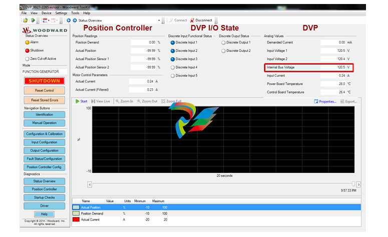
3. Use the DVP Service Tool to monitor the Internal Bus Voltage. This should typically be within a few
volts of the DVP input voltage.
Note: The service tool accesses the two input voltages (Input Voltage 1 and Input Voltage 2) and the
Internal Bus Voltage. It is important to read the Internal Bus Voltage for this test. The Internal Bus
Voltage is interrupted as part of the safety function.
4. Open the External Shutdown input, allowing the actuator to move to a fail-safe state. Verify steps “a”
and “b”. This procedure verifies that the safety function is operational.
a. On the Status Overview Page, verify the Internal Bus Voltage is decreasing from the value in
Input Voltage 1 and 2. It may take several minutes for the voltage to go below 20V.
On the Fault Status/Configuration Page, verify that the E-STOP 1 Tripped and E-STOP 2
Tripped are active:
| User name | Member Level | Quantity | Specification | Purchase Date |
|---|


-
 Basler Electric DECS-200 Digital Excitation Control System
 -
 Basler Electric GENERATOR PROTECTION SYSTEM BE1-GPS100
 -
 Jaquet FT3000 Speed measurement system
 -
 Hirschmann Industrial Ethernet Ruggedized Switch MACH1000 Family
 -
 Basler Electric BESTCOMSPlus®
 -
 ETEL AccurET MODULAR 300 EA-P2M-300-xxxxxA controller
 -
 Basler Electric ES Series Protection Relays
 -
 ABB Multifunction Protection and Switchbay Control Unit REF542plus
 -
 EMERSON AMS 2140 Machinery Health Analyzer
 -
 Hirschmann Industrial Ethernet Rail Switch RS20 Basic Family
 -
 GE Grid Solutions P40U Px40 USB Adaptor
 -
 ABB ontinuous Gas Analyzers AO2000 Series AO2040CU Ex Central Unit in Category 2G
 -
 ABB Advance Optima AO2000 Series Continuous gas analyzers Models AO2020. AO2040
 -
 Advance Optima Module Uras 14
 -
 SAACKE control optimization
 -
 SAACKE se@vis efficiency monitor
 -
 SAACKE se@vis pro
 -
 SAACKE se@vis eco
 -
 SAACKE se@vis compact
 -
 HIRSCHMANN Industrial ETHERNET Switch MICE MS20/MS30
 -
 HIRSCHMANN MICE Media modules
 -
 Kongsberg GL-10 Level Switch
 -
 B&R ACOPOSinverter P74 frequency converter
 -
 Beckhoff CX2020 | Basic CPU module (service phase)
 -
 Beckhoff CX1010 | Basic CPU module (service phase)
 -
 Beckhoff CX5120 | Embedded PC with Intel Atom® E3815
 -
 Beckhoff CP69xx-xxxx-0010 | Economy built-in Control Panel with DVI/USB Extended interface
 -
 Beckhoff CP29xx-0000 | Multi-touch built-in Control Panel with DVI/USB Extended interface
 -
 SAACKE Monoblock Rotary Cup Burner SKVJ-M
 -
 ABB Plantguard Fault Tolerant Technology Architecture and Software
 -
 OMRON H8PR-8/H8PR-8P H8PR-16/H8PR-16P H8PR-24/H8PR-24P Rotary Positioner
 -
 ABB PFSA107-Z42 DTU Stressometer Digital Transmission Unit
 -
 Nidec Mentor MP
 -
 IBA ibaNet-E
 -
 IBA FO Connection to Reflective Memory
 -
 IBA FO Connection to Siemens Systems
 -
 IBA Interface Cards For Fiber Optic Connections
 -
 IBA Field and Drive Buses
 -
 IBA ibaPADU-S Modular System
 -
 IBA ibaMAQS
 -
 STUCKE SYMAP®ARC
 -
 STUCKE SYMAP®R
 -
 STUCKE SYMAP®Compact
 -
 MOOG G123-825-001 BUFFER AMPLIFIER
 -
 Motorola MVME5100 Series VME Processor Modules
 -
 Motorola MVME162 Embedded Controller
 -
 HIMatrix Safety-Related Controller System Manual for the Modular Systems
 -
 Motorola MVME2400 Series VME Processor Module
 -
 Sieger System 57
 -
 KONGSBERG MRU product line continuation
 -
 Woodward easYgen-3100/3200 Genset Control for Multiple Unit Operation
 -
 Woodward MFR 300 Multifunction Relay / Measuring
 -
 ABB AX410, AX411, AX413, AX416, AX418, AX450, AX455 and AX456 Single and dual input analyzers for low level conductivity
 -
 ABB AX410, AX411, AX416, AX450 and AX455 Single and dual input analyzers
 -
 Woodward easYgen-1400 Technical Manual Genset Control
 -
 Woodward easYgen-400 Operation Manual Genset Control
 -
 Woodward High Output Digital Valve Positioner (DVP)DVP5000/DVP10000/DVP12000
 -
 Woodward High Output Digital Valve Positioner DVP5000 and DVP10000
 -
 Woodward TG611-13/-17 Overspeed Test Device Conversion Kit
 -
 Woodward MicroNet Safety Module (MSM)
 -
 Woodward 2301A Electronic Load Sharing and Speed Control 9905/9907 Series
 -
 Woodward-Service Bulletin 01671
 -
 UniOP eTOP40B 12.1” TFT color display
 -
 UniOP eTOP40 TFT Color display
 -
 UniOP eTOP33B 10.4” TFT color display
 -
 UniOP eTOP33C eTOP33-0050 Resistive touchscreen
 -
UniOP eTOP30. eTOP32 eTOP32-0050 Human-machine interface equipment
-
 UniOP eTOP20B and eTOP21B eTOP20B-0050
 -
 UniOP eTOP12 eTOP12-0050 Advanced human-machine interface equipment
 -
 UniOP eTOP11 eTOP11-0050 HMI
 -
 UniOP eTOP06C HMI
 -
 UniOP eTOP06 HMI
 -
 UniOP eTOP05EB eTOP05EB-DF45 HMI
 -
 UniOP eTOP05. eTOP05P Human-machine interface equipment
 -
 UniOP eTOP03 eTOP03-0046
 -
 UniOP eTOP507 507U2P1 eTOP Series 500 Human-Machine Interface
 -
 UniOP eTOP307
 -
 UniOP ETT-VGA Human-machine interface touch unit
 -
 UniOP ePAD32B, ePAD33B and ePAD33BT ePAD33B-0350
 -
 UniOP ePAD05 and ePAD06
 -
 UniOP CP02R-04 Human-machine interface
 -
 UniOP ERT-16 - Industrial PLC Workstation
 -
 UniOP ePAD03 and ePAD04
 -
 UNIOP EPALM10-DA71 state-of-the-art handheld HMI
 -
 Watlow SERIES CLS200 SPECIFICATION SHEET
 -
 Detailed Explanation of B&R Power Panel 300/400: The Core of Industrial Automation Control
 -
 YOKOGAWA Models ANB10S, ANB10D, ANR10S, ANR10D Node Units (for FIO)
 -
 Woodward ESDR 4 Current Differential Protection Relay
 -
 Woodward easYgen-3000 Genset Control for
 -
 Woodward CPC-II Current-to-Pressure Converter
 -
 Woodward 8290-189-EPG-installation-manual 8290-044
 -
 Woodward Product Change Notification 06946A
 -
 Woodward Product Change Notification 06912
 -
 Fisher™ 4660 High-Low Pressure Pilot
 -
 Flexible digital protection and control equipment SYMAP®
 -
 Woodward 723PLUS Digital Control
 -
 Woodward 505 Digital Controller For steam turbineses
 -
 Woodward 85018V2 505E Digital Governor for Extraction Steam Turbines
 -
Woodward 85018V1 Turbine Control Parameters
-
Woodward 26871 505 Enhanced Digital Control for Steam Turbines
-
 Woodward 03365 505E (Extraction / Admission)
 -
 KONGSBERG RMP420-Remote Multipurpose Input/Output
 -
 KONGSBERG RCU501 Remote Controller Unit
 -
 KONGSBERG RCU500 Remote Controller Unit
 -
 K-Gauge TOP KONGSBERG Tank Overfill Protection SystemFeatures
 -
 Kongsberg DPS112 DGNSS (DGPS/DGLONASS) sensor
 -
 Kongsberg d0000930-presafe-atex-report signed
 -
 HIMax TECHNICAL FACTS X Series
 -
 GE Multilin F650
 -
 GE MIF II - Legacy
 -
 GE PQM II Power QualIty Meter
 -
 Hydran 201Ti Mark IV Essential DGA monitoring for transformers
 -
 alstom AMS42/84 5B Amplifier SystemAmplifier Technology at its Best.
 -
 GE VMIVME-5576 Fiber-Optic Reflective Memory with Interrupts
 -
 GE Multilin 750/760 - Legacy Feeder Protection System
 -
 GE Fanuc Automation VMICPCI-7806 Specifications
 -
 VMIVME-7807 VME-7807RC* Intel® Pentium® M-Based VME SBC
 -
 GE Fanuc Automation VMIVME-7750 Specifications
 -
 FOXBORO Compact FBM240. Redundant with Readback, Discrete
 -
 FOXBORO FBM208/b, Redundant with Readback, 0 to 20 mA I/O Module
 -
 FOXBORO FBM201e Analog Input (0 to 20 mA) Interface Modules
 -
 Foxboro DCS FBM206 Pulse Input Module
 -
 FOXBORO FBM216 HART® Communication Redundant Input Interface Module
 -
 FOXBORO Z-Module Control Processor 270 (ZCP270)
 -
 FOXBORO Fieldbus Communications Module, FCM10Ef
 -
 FOXBORO Fieldbus Communications Module, FCM10E
 -
 Foxboro DCS Compact FBM241/c/d, Redundant, Discrete I/O Modules
 -
Foxboro FBM223 PROFIBUS-DP™ Communication Interface Module


