
Foxboro DCS Compact FBM241/c/d, Redundant, Discrete I/O Modules
Foxboro DCS Compact FBM241/c/d, Redundant, Discrete I/O
Modules
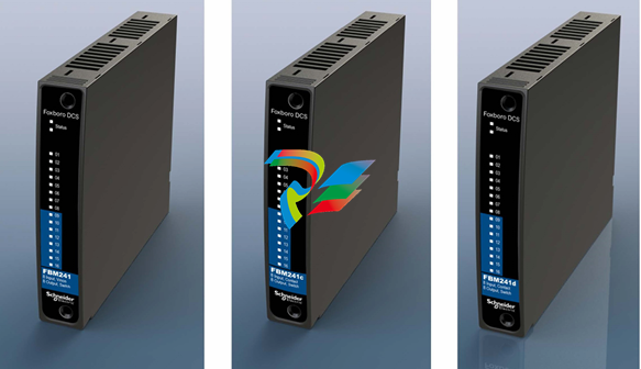
The Compact FBM241. FBM241c, and FBM241deach have eight discrete inputs and
eight discrete outputs available as a single or redundant module. A redundant pair of
the modules combine to provide redundancy at the FBM level with field I/O wired to
one commontermination assembly.
The Compact Channel Isolated, Discrete I/O Interface Modules (Compact FBM241/c/
d) have eight discrete input channels and eight discrete output channels. Associated
termination assemblies (TAs) support discrete input or output signals at voltages of
under 60 VDC, 120 VAC/125 VDC, or 240 VAC.
Depending on the type of I/O signal required, the TAs contain current limiting devices,
fuses, relays, or relay outputs with internal or external power source and fusing.
The module is available in three distinct types and each type with its associated TA
supports the following discrete inputs and outputs:
Each type of Fieldbus Module (FBM), without signal conditioning, uses a 15 to 60
VDCinput or output signal. Each discrete input and output is galvanically isolated
from other channels and ground. When used with external excitation, each discrete
input and output is group isolated.
The module performs signal conversion required to interface electrical input signals
from field sensors to the optionally redundant fieldbus. It executes the Discrete I/O or
Ladder Logic program, with the following configurable options: Input Filter Time, Fail
Safe Configuration, Fail-Safe Fall-Back, and Sustained or Momentary Outputs. If the
Momentary Output configuration is selected, then Pulse Output Interval is also
configurable
Features
• 8discrete inputs
• 8discrete outputs
• Single or Redundant Module
• Supports discrete inputs/output signals at voltages of:
◦ 15to60VDC
◦ 120VAC/125VDC
◦ 240VAC
• Eachinput and output is galvanically isolated: group isolated when used with
external excitation
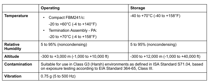
• Compact,rugged design suitable for enclosure in Class G3 (harsh) environments
• Executes the Discrete I/O or Ladder Logic program, with the following
configurable options: Input Filter Time, Fail Safe Configuration, Fail-Safe Fall
Back, and Sustained or Momentary Outputs
• Various Termination Assemblies (TAs) that contain:
◦ Current limiting devices
◦ Fuses
◦ Relayoutputs
◦ Relayoutputs with internal or external power source and fusing
◦ Solid state outputs
Redundant Outputs
Aredundant contact output function block, COUTR, is used for each redundant pair of
outputs. The COUTR block handles output writes and initialization logic for the
redundant channels. On each write of the COUTR block, identical output writes are
sent to both modules, fully exercising the Fieldbus and the logic circuitry of each
module. You can select a sustained output that follows the block input or a pulsed
output with a selectable pulse width.
Whenafailure is detected in the modules, its output is marked as BAD and the
corresponding channel in the good module automatically continues to drive the
discrete outputs. Each output channel drives an externally powered load. Power for
each Compact FBM241 module is diode OR’d together in the redundant adapter to
help assure redundant power. The microprocessor of each module executes the
digital output application program, plus diagnostic routines that validate the health of
the FBM.
Compact Design
The Compact FBM241’s design is narrower than the standard 200 Series FBMs. It
has a rugged Acrylonitrile Butadiene Styrene (ABS) exterior for physical protection of
the circuits. Enclosures specially designed for mounting the FBMs provide various
levels of environmental protection, up to harsh environments, per ISA Standard
S71.04
Visual Indicators
Light-emitting diodes (LEDs) incorporated into the front of the module provide visual
indication of the Fieldbus Module operational status, as well as the discrete states of
the individual input and output points.
Easy Removal/Replacement
The module mounts on a Compact 200 Series baseplate. Two screws on the FBM
help secure the module to the baseplate.
The module can be removed or replaced without removing field device termination
cabling, power, or communication cabling.
Redundant modules must be located in adjacent positions on the baseplate, with the
first module located in an odd-numbered position (for example, the positions labelled
3 and 4). To achieve redundancy, a redundant adapter module is placed on the two
adjacent baseplate termination cable connectors to provide termination for a single
cable. A single termination cable connects from the redundant adapter to the
associated termination assembly (TA).
Whenredundant, either module can be replaced without upsetting field input signals
to the good module. Each module can be removed or replaced without removing field
termination cabling, power, or communications cabling
Fieldbus Communication
AFieldbus Communications Module or a Control Processor interfaces to the
redundant 2 Mbps module Fieldbus used by the FBMs. The Compact FBM241/c/d
accepts communication from either path (A or B) of the redundant 2 Mbps Fieldbus. If
one path is unsuccessful or is switched at the system level, the module continues
-
 Hirschmann M1-8SFP Switche
 -
 Hirschmann Industrial Ethernet Ruggedized Switch MACH1000 Family
 -
 Basler Electric, Solid State Protective Relay, BE1-60
 -
BASLER ELECTRIC SR4A-2B15B3A Static Voltage Regulator
-
.png) BASLER ELECTRIC EXCITER DIODE MONITOR EDM-200
BASLER ELECTRIC EXCITER DIODE MONITOR EDM-200 -
.png) BASLER ELECTRIC DECS125-15-B2C5 DIGITAL EXCITATION CONTROL SYSTEM V 2.0.9
BASLER ELECTRIC DECS125-15-B2C5 DIGITAL EXCITATION CONTROL SYSTEM V 2.0.9 -
 BASLER ELECTRIC BE1-851 OVERCURRENT PROTECTION RELAY MECHANISM
 -
 Basler Electric BE1-51A / BE151A
 -
 Basler Electric BE1-40Q Loss of Excitation Relay
 -
 Basler Electric BE1-87G Variable Percentage Differential Relay
 -
 Basler Electric BE1-11 Protection System I5A3M2P2N0EA00
 -
 BASLER ELECTRIC DECS-200-1C Digital Excitation Control System
 -
 Basler Electric / Kohler BE1-11g Generator Protection Relay G5A3M2J2N0E000
 -
BASLER ELECTRIC DECS125-15 DIGITAL EXCITATION CONTROL SYSTEM
-
 BASLER ELECTRIC BE1-951 OverCurrent Protecton System
 -
Basler Electric DECS-200-1L Digital Excitation Control System
-
 Basler Electric DGC-2020HD-5NS1DNSBA Digital Genset Controller -
 -
 BASLER ELECTRIC BE1-81T1EE1WA0N1F / BE181T1EE1WA0N1F
 -
 BASLER ELECTRIC BE1-25M1EA6PN5R1F / BE125M1EA6PN5R1F
 -
 BASLER ELECTRIC DECS-250-LN1SN1N DIGITAL EXCITATION CONTROL SYSTEM
 -
Basler Electric DECS-250-CN2CN 1N Digital Excitation Control System Unit
-
 BASLER ELECTRIC DECS-300-C0N0 DIGITAL EXCITATION CONTROL SYSTEM
 -
 BASLER ELECTRIC BE1-87T-A1E-A1J-D0S1F / BE187TA1EA1JD0S1F
 -
BASLER ELECTRIC BE1-11-G6D1M0J2P0E000 Protection System
-
 BASLER ELECTRIC BE1-GPS100-E4N1H1N GENERATOR PROTECTION SYSTEM
 -
 Jaquet Relay card (Auxiliary module) FTV 3090 377Z-03985
 -
 Jaquet Trip Chain Control card FTBU 3034 377Z-05030
 -
 Jaquet with input card -E04 FTFU 3024 -E04 377Z-05855
 -
 Jaquet with input card -E03 FTFU 3024- E03 377Z-03983
 -
 Jaquet FTFU 3024- E02 377Z-03982 with input card -E02
 -
 Jaquet FTFU 3024-E01 377Z-03981 with input card -E01
 -
 Hirschmann RS20-2400T1T1SDAE Industrial Managed Ethernet Switch
 -
 Hirschmann BELDEN EAGLE30-04022O6TT999SCCV9HSE3F
 -
 Hirschmann MM3-2FXS2/2TX MICE Media Module
 -
 Hirschmann RS20-1600M2M2SDAPHC08.0.05 Industrial Managed Switch
 -
 Hirschmann OZD Profi 12M G12-1300 PRO Fieldbus Repeater
 -
 Hirschmann SPIDER 4TX/1FX-ST EEC Industrial Ethernet Switch
 -
 Hirschmann MM2-2FXM3/2TX1 MICE Media Module
 -
 Hirschmann RS20-2400M2M2SDAPHC09.0.14 Industrial Switch
 -
 Hirschmann RS20-0400M2M2SDAEHC07.1.05 OpenRail Switch
 -
 Hirschmann OZD Profi 12M G12-EEC Fieldbus Repeater
 -
 HIRSCHMANN MDA422-1/2-3.5c-23/46 sensor
 -
Hirschmann RS30-2402T1T1SDAUHC Managed Industrial Switch
-
 Hirschmann OZD GENIUS G12 Industrial Switche
 -
 Hirschmann OZD 485 G12-1300 PRO Fieldbus Repeater
 -
 Hirschmann MM2-2FXM2 MICE Media Module
 -
 Hirschmann RS20-1600S2T1SDAUHC Managed Industrial Switch
 -
 Hirschmann MS20-0800SAAEHH04.2.04 MICE Switch
 -
 Hirschmann SPIDER 4TX/1FX EEC Unmanaged Industrial Switch
 -
 HIRSCHMANN MS4128-L3P EEC Managed Industrial Ethernet Switch
 -
 HIRSCHMANN RS20-0400M2T1SDAPHC08.0.01 Managed Switch
 -
 ETEL EA-S0M-400-40/80A-0000-00 AccurET Modular Power Supply
 -
 ETEL EA-B0I-0-0-0000-00 Backplane Interface Board
 -
 ETEL EA-P2M-400-15/40A-0100-00 Position Controller
 -
ETEL EA-P2M-400-15/40A-0000-00 Position Controller
-
 ETEL EA-P2M-400-10/20A-0100-01 Position Controller
 -
 ETEL EA-P2M-400-10/20A-0000-01 Position Controller
 -
 ETEL EA-P2M-400-5/10A-0100-01 Position Controller
 -
 ETEL EA-P2M-048-2.5/5A-0000-01 Modular Position Controller
 -
 ETEL EA-S0M-300-40/80A-0000-00 Power Supply Module
 -
 ETEL EA-P2M-300-07/15A-0100-01 Position Controller
 -
 ETEL EA-P2M-300-07/15A-0000-01: Modular Position Controller
 -
 ETEL EA-P2M-300-4/7.5A-0100-01 Overview
 -
 Basler Electric MOC2. Motor Operated Potentiometer
 -
 Basler Electric BE1-11 RTD Module, Resistance Temperature Detector
 -
 Basler Electric RDP-110C, Remote Display Panel
 -
 Basler Electric VRM-2020. Voltage Regulation Module
 -
 Basler Electric IDP-1500. Interactive Display Panel
 -
 Basler Electric AEM-2020. Analog Expansion Module
 -
 Basler Electric IDP-2020. Interactive Display Panel
 -
 Basler Electric CEM-2020. Contact Expansion Module
 -
 Basler Electric CEM-125. Contact Expansion Module
 -
 Basler Electric BE2000E, Digital Voltage Regulator
 -
 Basler Electric SMC-150. Synchronous Motor Controller
 -
 Basler Electric AVC125-10. Voltage Regulator
 -
 Basler Electric BE1-25. Sync-Check Relay
 -
 Basler Electric DGC-2020ES, Digital Genset Controller
 -
 ETEL EA-P2M-400-5/10A-0000-01 Position Controller
 -
 Basler Electric BE1-64F, Ground Fault Relay
 -
 Basler Electric BE1-79M, Multi Shot Reclosing Relay
 -
 Basler Electric BE1-81O/U, Digital Frequency Relay
 -
 Basler Electric BE1-87B, High Impedance Bus Differential Relay
 -
 Basler Electric BE1-79A, Reclosing Relay
 -
 Basler Electric BE1-27. BE1-59. BE1-27/59. Voltage Relay
 -
 Basler Electric SMC-250. Synchronous Motor Controller
 -
 Basler Electric SGC-250N, Synchronous Generator Controller
 -
 Basler Electric SGC-250. Synchronous Generator Controller
 -
 Basler Electric BE1-50/51 Plug and Play and Retrofit Relays
 -
 Basler Electric DECS-2100. Digital Excitation Control System
 -
 Basler Electric DECS-250E, Digital Excitation Control System
 -
 Basler Electric BE1-700V, Voltage Only Digital Protective Relay
 -
 Basler Electric DECS-250. Digital Excitation Control System
 -
 Basler Electric DECS-450. Digital Excitation Control System
 -
 Basler Electric DECS-150. Digital Excitation Control System
 -
 Basler Electric ES-49. Temperature Relay
 -
 Basler Electric ES-81O/U, ES-81O,ES-81U Overfrequency Relay
 -
Basler Electric ES-74V, DC Voltage Sensing Relay
-
Basler Electric ES-27/59. Under/Overvoltage Relay
-
 Basler Electric ES-27. Undervoltage Relay
 -
 Basler Electric ES-25. Sync-Check Relay
 -
 Basler Electric ES-47, ES-47N Phase Sequence Relay
 -
Basler Electric ES-37.ES-37/51 Undercurrent Relay
-
 Basler Electric ES-32. Reverse Power Relay
 -
Basler Electric ES-59. Overvoltage Relay
-
 Basler Electric ES-55. Power Factor Relay
 -
 Basler Electric DGC-2020HD, Digital Genset Controller
 -
 Basler Electric BE1-FLEX, Protection, Automation, and Control System
 -
 Schneider GUTOR OC0935 Power Factor Sampling Board
 -
 Schneider GUTOR OC0922 Analog Signal Isolation Board
 -
 Schneider GUTOR OC0908 Battery Voltage Detection Board
 -
Schneider GUTOR OC0947 Temperature / IGBT Sampling Board
-
 Schneider GUTOR OP2601 Communication Expansion Board
 -
 Schneider Electric GUTOR OP2312 bypass control board
 -
 Schneider Electric GUTOR OP2130 Cooling Fan Monitoring & Control Board
 -
 Schneider Electric GUTOR OP2010 Battery Test Board / Battery Management Diagnostic Card
 -
Schneider Electric GUTOR OP2552 Three-phase Power Connection Board Assembly
-
 Schneider Electric GUTOR OP1922A Parallel Control Board / Load-Sharing Synchronization Module
 -
 Schneider Electric GUTOR OP6290B Inverter Feedback Acquisition Board / Signal Scaling Module
 -
Schneider GUTOR OP6280 Basic Signal Board
-
Schneider Electric GUTOR OP2456 / OP2456B Main control board
-
 Schneider Electric GUTOR OP2452 Power Plug-in Panel
 -
 Schneider Electric GUTOR OP2450 Parallel Communication Board
 -
Schneider Electric GUTOR OP2406 Interface Fuse Monitoring Board
-
 Schneider Electric GUTOR OC0919 High-Power Semiconductor Module
 -
 Schneider Electric GUTOR OP6281A System Logic Interface Board
 -
 Schneider Electric GUTOR OP6285A Power Signal Acquisition Board
 -
 Schneider Electric GUTOR OP2438 Fan Monitor & Drive Protection Board
 -
Schneider Electric GUTOR OP2446 Main Control CPU Board


