
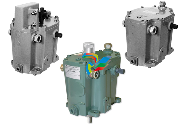
Woodward TG-17 9904-800 Legacy Mechanical Governors
Internally, the TG-13/TG-17 and TG611-13/TG611-17 governor consists of the following basic items:
• oil pump
• oil accumulator
• speeder-spring
• ballhead and pilot-valve bushing assembly
• pilot-valve plunger
• servopiston
• droop adjustment
• speed adjustment
• terminal lever and shafts
A schematic diagram (Figure 4-1) shows the relationship of these various items and provides a visual
means of understanding the operation of the TG governor.
Description of Operation
Oil Pressure and Distribution
The governor is normally driven by the turbine through a flexible coupling. The inner gerotor of the oil
pump is keyed to the governor drive shaft and pilot-valve bushing. The pump draws oil from the sump and
distributes it through the oil passages within the case. Oil is also discharged to the spring-loaded
accumulator. The relief valve/accumulator maintains 1034 kPa (150 psi) operating pressure at rated
speed for the TG-13/TG611-13 and 1379 kPa
(200 psi) operating pressure at rated speed for the TG-17/TG611-17. Excess pressure compresses the
accumulator springs and oil is released to sump during steady-state operation.
A change in speed and centrifugal force moves the flyweights out or in. This moves the pilot-valve
plunger either upward or downward depending on whether it is an increase or decrease in speed. Plunger
movement opens the control port and releases oil either to sump or to the underside of the servopiston.
During servopiston movement in the increase-fuel direction, the accumulator supplements the system oil
supply with its stored volume of high-pressure oil and helps maintain the full work capacity of the
governor.
Ballhead Operation
The ballhead assembly contains two flyweights, speeder spring, thrust bearing, pilot-valve plunger and
pilot-valve bushing. As the flyweights are rotated, they produce a centrifugal force that is opposed by the
downward force of the speeder-spring. The speeder-spring force can be varied by adjusting the speed
setting screw, or speed-setting lever.
A thrust bearing on top of the flyweight toes permits the pilot-valve bushing to rotate around the pilot
valve plunger. This reduces friction between the bushing and plunger.
Pilot-Valve Function
When the turbine is running at the governor set speed, the pilot-valve plunger is centered, covering the
control ports of the pilot-valve bushing. In this position, no oil is discharged from or flows to the
servopiston, and the governor terminal shaft cannot move. A change in either the flyweight centrifugal
force (speed change) or the speeder-spring force (speed setting) moves the plunger from its centered
position. Plunger movement opens the control port and releases oil either to sump or to the underside of
the servopiston.
The pilot-valve plunger lowers if:
• An additional load slows the turbine and governor speed. This decreases the centrifugal force of the
rotating flyweights which opposes the force for the speeder spring.
• The turbine speed is unchanged, but speeder-spring force is increased by raising the governor
speed setting with the speed-setting screw or speed-setting lever.
Lowering the pilot-valve plunger opens the control ports. High-pressure oil is released to the area below
the servopiston, forcing the servopiston upwards. This rotates the governor terminal shaft in the increase
steam direction.
As the servopiston rises, the speeder-spring force is decreased by movement of the terminal lever and
allows the pilot-valve plunger to rise. The flow of high-pressure oil to the servopiston is closed off by the
control land, stopping the upward motion of the servopiston.
The pilot-valve plunger raises if:
• The centrifugal force of the rotating flyweights is increased by a load decrease on the turbine. This
causes an increase in turbine and governor speed.
• The governor speed is lowered by reducing the speeder-spring force with the speed-adjusting screw.
Raising the pilot-valve plunger again opens the ports, but this time control oil is released to sump from
below the servopiston. High-pressure oil in the area above the servopiston cylinder forces the piston
down. This rotates the terminal shaft in the decrease-steam or fuel direction. Speeder-spring pressure
increases, forcing the pilot-valve plunger downward. Terminal-shaft movement stops as the control land
covers the ports, stopping the release of control oil.
Droop-Adjusting Lever Function
Note that as the terminal lever rotates in the increase-fuel direction, the droop-adjusting lever is lifted and
decreases the speeder-spring force on the flyweights. Thus, the ballhead is allowed to re-center the pilot
valve plunger at lower speeds as fuel is increased. This characteristic is referred to as “speed droop”.
Closing the control port stops further movement of the servopiston simultaneously with the return of
turbine speed to a speed determined by the new speed or spring force.
When moving in the decrease-fue
TG17 Screw, 2400 rpm, CCW Rotation, ATEX, Rated Speed
@2° Droop = 1950 rpm
9904-800
TG17 Screw, 2400 rpm, CW Rotation, ATEX, Rated Speed
@2° Droop = 1950 rpm
9904-801
TG17 Screw, 2400 rpm, CCW Rotation, ATEX, Rated Speed
@2° Droop = 2010 rpm
9904-802
TG17 Screw, 4000 rpm, CCW Rotation, ATEX, Rated Speed
@2° Droop = 4035 rpm
9904-803
TG17 Screw, 4000 rpm, CW Rotation, ATEX, Rated Speed
@2° Droop = 3910 rpm
9904-804
TG17 Screw, 4000 rpm, CCW Rotation, ATEX, Rated Speed
@2° Droop = 3910 rpm
9904-805
TG17 Screw, 6000 rpm, CW Rotation, ATEX, Rated Speed
@2° Droop = 5860 rpm
9904-806
TG17 Screw, 6000 rpm, CCW Rotation, ATEX, Rated Speed
@2° Droop = 5860 rpm
9904-807
TG17 Lever, 2400 rpm, CCW Rotation, ATEX, Rated Speed
@2° Droop = 2010 rpm
9904-808
TG17 Lever, 2400 rpm, CW Rotation, ATEX, Rated Speed
@2° Droop = 2010 rpm
9904-809
TG17 Lever, 4000 rpm, CCW Rotation, ATEX, Rated Speed
@2° Droop = 4035 rpm
9904-810
TG17 Lever, 4000 rpm, CW Rotation, ATEX, Rated Speed
@2° Droop = 4035 rpm
9904-811
TG17 Lever, 6000 rpm, CCW Rotation, ATEX, Rated Speed
@2° Droop = 6000 rpm
9904-812
TG17 Lever, 6000 rpm, CW Rotation, ATEX, Rated Speed
@2° Droop = 6000 rpm
*Documentation: Product Spec: 04038. Manual: 04042
9904-813
| User name | Member Level | Quantity | Specification | Purchase Date |
|---|


-
 Basler Electric DECS-200 Digital Excitation Control System
 -
 Basler Electric GENERATOR PROTECTION SYSTEM BE1-GPS100
 -
 Jaquet FT3000 Speed measurement system
 -
 Hirschmann Industrial Ethernet Ruggedized Switch MACH1000 Family
 -
 Basler Electric BESTCOMSPlus®
 -
 ETEL AccurET MODULAR 300 EA-P2M-300-xxxxxA controller
 -
 Basler Electric ES Series Protection Relays
 -
 ABB Multifunction Protection and Switchbay Control Unit REF542plus
 -
 EMERSON AMS 2140 Machinery Health Analyzer
 -
 Hirschmann Industrial Ethernet Rail Switch RS20 Basic Family
 -
 GE Grid Solutions P40U Px40 USB Adaptor
 -
 ABB ontinuous Gas Analyzers AO2000 Series AO2040CU Ex Central Unit in Category 2G
 -
 ABB Advance Optima AO2000 Series Continuous gas analyzers Models AO2020. AO2040
 -
 Advance Optima Module Uras 14
 -
 SAACKE control optimization
 -
 SAACKE se@vis efficiency monitor
 -
 SAACKE se@vis pro
 -
 SAACKE se@vis eco
 -
 SAACKE se@vis compact
 -
 HIRSCHMANN Industrial ETHERNET Switch MICE MS20/MS30
 -
 HIRSCHMANN MICE Media modules
 -
 Kongsberg GL-10 Level Switch
 -
 B&R ACOPOSinverter P74 frequency converter
 -
 Beckhoff CX2020 | Basic CPU module (service phase)
 -
 Beckhoff CX1010 | Basic CPU module (service phase)
 -
 Beckhoff CX5120 | Embedded PC with Intel Atom® E3815
 -
 Beckhoff CP69xx-xxxx-0010 | Economy built-in Control Panel with DVI/USB Extended interface
 -
 Beckhoff CP29xx-0000 | Multi-touch built-in Control Panel with DVI/USB Extended interface
 -
 SAACKE Monoblock Rotary Cup Burner SKVJ-M
 -
 ABB Plantguard Fault Tolerant Technology Architecture and Software
 -
 OMRON H8PR-8/H8PR-8P H8PR-16/H8PR-16P H8PR-24/H8PR-24P Rotary Positioner
 -
 ABB PFSA107-Z42 DTU Stressometer Digital Transmission Unit
 -
 Nidec Mentor MP
 -
 IBA ibaNet-E
 -
 IBA FO Connection to Reflective Memory
 -
 IBA FO Connection to Siemens Systems
 -
 IBA Interface Cards For Fiber Optic Connections
 -
 IBA Field and Drive Buses
 -
 IBA ibaPADU-S Modular System
 -
 IBA ibaMAQS
 -
 STUCKE SYMAP®ARC
 -
 STUCKE SYMAP®R
 -
 STUCKE SYMAP®Compact
 -
 MOOG G123-825-001 BUFFER AMPLIFIER
 -
 Motorola MVME5100 Series VME Processor Modules
 -
 Motorola MVME162 Embedded Controller
 -
 HIMatrix Safety-Related Controller System Manual for the Modular Systems
 -
 Motorola MVME2400 Series VME Processor Module
 -
 Sieger System 57
 -
 KONGSBERG MRU product line continuation
 -
 Woodward easYgen-3100/3200 Genset Control for Multiple Unit Operation
 -
 Woodward MFR 300 Multifunction Relay / Measuring
 -
 ABB AX410, AX411, AX413, AX416, AX418, AX450, AX455 and AX456 Single and dual input analyzers for low level conductivity
 -
 ABB AX410, AX411, AX416, AX450 and AX455 Single and dual input analyzers
 -
 Woodward easYgen-1400 Technical Manual Genset Control
 -
 Woodward easYgen-400 Operation Manual Genset Control
 -
 Woodward High Output Digital Valve Positioner (DVP)DVP5000/DVP10000/DVP12000
 -
 Woodward High Output Digital Valve Positioner DVP5000 and DVP10000
 -
 Woodward TG611-13/-17 Overspeed Test Device Conversion Kit
 -
 Woodward MicroNet Safety Module (MSM)
 -
 Woodward 2301A Electronic Load Sharing and Speed Control 9905/9907 Series
 -
 Woodward-Service Bulletin 01671
 -
 UniOP eTOP40B 12.1” TFT color display
 -
 UniOP eTOP40 TFT Color display
 -
 UniOP eTOP33B 10.4” TFT color display
 -
 UniOP eTOP33C eTOP33-0050 Resistive touchscreen
 -
UniOP eTOP30. eTOP32 eTOP32-0050 Human-machine interface equipment
-
 UniOP eTOP20B and eTOP21B eTOP20B-0050
 -
 UniOP eTOP12 eTOP12-0050 Advanced human-machine interface equipment
 -
 UniOP eTOP11 eTOP11-0050 HMI
 -
 UniOP eTOP06C HMI
 -
 UniOP eTOP06 HMI
 -
 UniOP eTOP05EB eTOP05EB-DF45 HMI
 -
 UniOP eTOP05. eTOP05P Human-machine interface equipment
 -
 UniOP eTOP03 eTOP03-0046
 -
 UniOP eTOP507 507U2P1 eTOP Series 500 Human-Machine Interface
 -
 UniOP eTOP307
 -
 UniOP ETT-VGA Human-machine interface touch unit
 -
 UniOP ePAD32B, ePAD33B and ePAD33BT ePAD33B-0350
 -
 UniOP ePAD05 and ePAD06
 -
 UniOP CP02R-04 Human-machine interface
 -
 UniOP ERT-16 - Industrial PLC Workstation
 -
 UniOP ePAD03 and ePAD04
 -
 UNIOP EPALM10-DA71 state-of-the-art handheld HMI
 -
 Watlow SERIES CLS200 SPECIFICATION SHEET
 -
 Detailed Explanation of B&R Power Panel 300/400: The Core of Industrial Automation Control
 -
 YOKOGAWA Models ANB10S, ANB10D, ANR10S, ANR10D Node Units (for FIO)
 -
 Woodward ESDR 4 Current Differential Protection Relay
 -
 Woodward easYgen-3000 Genset Control for
 -
 Woodward CPC-II Current-to-Pressure Converter
 -
 Woodward 8290-189-EPG-installation-manual 8290-044
 -
 Woodward Product Change Notification 06946A
 -
 Woodward Product Change Notification 06912
 -
 Fisher™ 4660 High-Low Pressure Pilot
 -
 Flexible digital protection and control equipment SYMAP®
 -
 Woodward 723PLUS Digital Control
 -
 Woodward 505 Digital Controller For steam turbineses
 -
 Woodward 85018V2 505E Digital Governor for Extraction Steam Turbines
 -
Woodward 85018V1 Turbine Control Parameters
-
Woodward 26871 505 Enhanced Digital Control for Steam Turbines
-
 Woodward 03365 505E (Extraction / Admission)
 -
 KONGSBERG RMP420-Remote Multipurpose Input/Output
 -
 KONGSBERG RCU501 Remote Controller Unit
 -
 KONGSBERG RCU500 Remote Controller Unit
 -
 K-Gauge TOP KONGSBERG Tank Overfill Protection SystemFeatures
 -
 Kongsberg DPS112 DGNSS (DGPS/DGLONASS) sensor
 -
 Kongsberg d0000930-presafe-atex-report signed
 -
 HIMax TECHNICAL FACTS X Series
 -
 GE Multilin F650
 -
 GE MIF II - Legacy
 -
 GE PQM II Power QualIty Meter
 -
 Hydran 201Ti Mark IV Essential DGA monitoring for transformers
 -
 alstom AMS42/84 5B Amplifier SystemAmplifier Technology at its Best.
 -
 GE VMIVME-5576 Fiber-Optic Reflective Memory with Interrupts
 -
 GE Multilin 750/760 - Legacy Feeder Protection System
 -
 GE Fanuc Automation VMICPCI-7806 Specifications
 -
 VMIVME-7807 VME-7807RC* Intel® Pentium® M-Based VME SBC
 -
 GE Fanuc Automation VMIVME-7750 Specifications
 -
 FOXBORO Compact FBM240. Redundant with Readback, Discrete
 -
 FOXBORO FBM208/b, Redundant with Readback, 0 to 20 mA I/O Module
 -
 FOXBORO FBM201e Analog Input (0 to 20 mA) Interface Modules
 -
 Foxboro DCS FBM206 Pulse Input Module
 -
 FOXBORO FBM216 HART® Communication Redundant Input Interface Module
 -
 FOXBORO Z-Module Control Processor 270 (ZCP270)
 -
 FOXBORO Fieldbus Communications Module, FCM10Ef
 -
 FOXBORO Fieldbus Communications Module, FCM10E
 -
 Foxboro DCS Compact FBM241/c/d, Redundant, Discrete I/O Modules
 -
Foxboro FBM223 PROFIBUS-DP™ Communication Interface Module


