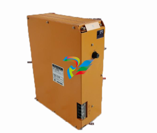
ABB Analog Input/Output Module 07 AC 91
The analog input/output module 07 AC 91 is used as a
remote module on the CS31 system bus. It contains 16
analog input/output channels that can be configured in
two operating modes:
• Operating mode "12 bits":
8 input channels, individually configurable
±10 V or 0...20 mA, 12 bit resolution plus
8 output channels, individually configurable
±10 V or 0...20 mA, 12 bit resolution
• Operating mode "8 bits":
16 channels, configurable in pairs as inputs or
outputs, 0...10 V oder 0...20 mA, 8 bit resolution
• The configuration is set with DIL switches
The PLC offers an interconnection element
ANAI4_20 for measuring signals of 4...20 mA (refer
to 907 PC 331. connection element library).
Intended purpose
The analog input/output module 07 AC 91 is used as a
remote module on the CS31 system bus. It contains 16
analog input/output channels that can be configured in
two operating modes:
• Operating mode "12 bits":
8 input channels, individually configurable
±10 V or 0...20 mA, 12 bit resolution plus
8 output channels, individually configurable
±10 V or 0...20 mA, 12 bit resolution
• Operating mode "8 bits":
16 channels, configurable in pairs as inputs or
outputs, 0...10 V oder 0...20 mA, 8 bit resolution
• The configuration is set with DIL switches.
The module 07 AC 91 uses up to eight input words on the
CS31 system bus plus up to eight output words. In the
operating mode "8 bits", 2 analog values are packed into
one word.
The operating voltage of the unit is 24 V DC. The CS31
system bus connection is electrically isolated from the
rest of the module.
The module offers a number of diagnosis functions (see
chapter "Diagnosis and displays").
Displays and operating elements on the
front panel
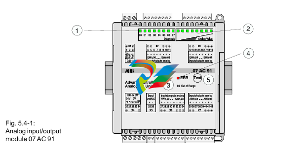
1
8 green LEDs for channel selection and diagnosis
2 8 green LEDs for analog value display of a channel
3 List of diagnosis information relating to the LEDs,
when they are used for diagnosis display
4 Red LED for error messages
5 Test button
Electrical connection
The module can be installed on a DIN rail (15 mm high) or
with 4 screws. The figure on the next page shows the
electrical connection for the input/output module.


.png)


