
ABB AC500 Product Series: Installation and Connection Guide
ABB AC500 Product Series: Installation and Connection Guide
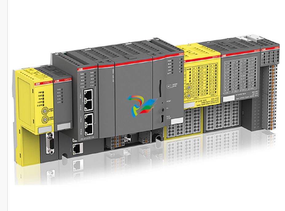
This document provides comprehensive installation and connection instructions for various modules within the ABB AC500 product series. It covers terminal bases (TB51x-TB54x, TB56xx-2ETH), CPU modules (PM5xx, PM595, PM56xx-2ETH), communication modules (CM582-DP, CM589-PNIO(-4)), and I/O modules (TU5xx, DC522, DC523, DC532, DI524, DO524, DO526, AI523, AI531, AO523, AX521, AX522, CI5x1, CI5x2, CI541-DP, CI542-DP). The document emphasizes safe handling, proper installation, and detailed connection specifications for each component.
General Safety and Installation Guidelines
Throughout the document, a critical warning is reiterated: "Risk of injury to personnel and damage to PLC modules!" Improper installation and maintenance can lead to personal injury and module damage. Therefore, all installation and maintenance work must be performed by skilled electricians in accordance with technical regulations, specifications, and relevant standards (e.g., EN 60204-1).
Dimensions for all modules are provided in millimeters, with inches in parentheses. For screw mounting, it is crucial to use wall mounting accessories (TA526 or TA543 for PM595) to prevent modules from bending and damage. These accessories snap into the rear of the module, similar to DIN rails, and the module is then tightened with M4 screws (max torque 1.2 Nm) from the front.
Terminal Bases (TB51x-TB54x and TB56xx-2ETH)
These sections detail the assembly, disassembly, dimensions, and connection specifications for various terminal bases.
TB51x-TB54x: Features I/O bus, processor module slots, communication module slots, fieldbus plug interface (not for TB523-2ETH), 24V DC power supply, serial interfaces (COM1, COM2), Ethernet, and ARCNET network interfaces. Pin assignments for power (L+, M, FE), COM1 (RS-485, RS-232 signals), COM2 (RS-232, RS-485 signals, 5V supply), ARCNET, and Ethernet (RJ45) are provided.
TB56xx-2ETH: Specifically designed for PM56xx-2ETH processor modules. It includes I/O bus, processor and communication module slots, CAN interface, 24V DC power supply, serial interface COM1, and Ethernet network interfaces. Detailed pin assignments for CAN (CAN_GND, CAN_L, CAN_SHLD, CAN_H), power (L+, M, FE), COM1 (RS-485, RS-232 signals), and Ethernet (RJ45) are given.
For both terminal base types, a crucial note advises keeping terminal boards connected even if interfaces are unused to prevent corrosion, especially for "XC" (extreme condition) versions in salt spray environments, where TA535 protective covers should be used.
Processor Modules (PM5xx, PM595, PM56xx-2ETH)
These sections describe the assembly, disassembly, dimensions, and connection interfaces of the CPU modules.
PM5xx (-y): Includes models like PM572, PM573-ETH, PM582, PM583-ETH, PM585-ETH, PM590-ARCNET, PM590-ETH, PM591-ETH, PM592-ETH. Connection details include status displays (7-segment), triangular and square displays for "project" and "status," status LEDs, function keys, SD memory card slots, and a label area. Specific compatibility notes are provided, e.g., PM591-2ETH only with TB523-2ETH, and PM57x/58x/59x-ETH modules with specific TB5xx terminal bases.
PM595: Includes PM595-4ETH-F and PM595-4ETH-M-XC. Features I/O bus for I/O modules, LEDs for fieldbus status, battery cover and display, LEDs for processor module status, RJ45 interfaces for fieldbus and Ethernet, memory card slot, reset button, and run/stop switch.
PM56xx-2ETH: Includes PM5630-2ETH, PM5650-2ETH, PM5670-2ETH, PM5675-2ETH. Similar to PM5xx, it details status displays, LEDs, function keys, and memory card slots. It explicitly states that PM56xx-2ETH processor modules must only be used with TB56xx-2ETH terminal bases.
All processor modules have a warning regarding incorrect battery use potentially causing fire or explosion.
Communication Modules (CM582-DP, CM589-PNIO(-4))
These modules facilitate communication with various fieldbus systems.
CM582-DP: Assembly, disassembly, dimensions, and connection details for PROFIBUS DP communication. It features status LEDs and rotary switches for setting PROFIBUS ID. Pin assignments for PROFIBUS (RxD/TxD-P/N, CNTR-P, DGND, VP) are provided.
CM589-PNIO(-4): Assembly, disassembly, dimensions, and connection details for PROFINET IO communication. It includes status LEDs and rotary switches for setting I/O device identifiers. Ethernet network interface pin assignments (TxD+/-, RxD+/-, NU) are detailed.
For unused connectors on communication modules, TA535 accessories are recommended in corrosive environments.
I/O Modules (TU5xx, DC522, DC523, DC532, DI524, DO524, DO526, AI523, AI531, AO523, AX521, AX522, CI5x1, CI5x2, CI541-DP, CI542-DP)
The document covers a wide range of I/O modules, each with specific connection details, LED indicators, and process voltage considerations.
Terminal Units (TU5xx): TU515, TU531, TU541, TU516(-XC), TU532(-XC), TU542(-XC), TU516-H. These are terminal devices for I/O modules. "H" suffix indicates hot-swappable I/O modules (from index F0), provided communication interface modules (CI5xx) are also from index F0. A warning is given against hot-swapping modules below index F0.
Digital I/O Modules (DC522, DC523, DC532, DI524, DO524, DO526): These modules handle digital inputs and outputs. They feature yellow LEDs for signal status, green LEDs for process voltage (UP, UP3, UP4), and red LEDs for errors. All I/O channels are protected against reverse polarity, reverse supply, and continuous overvoltage up to 30 VDC. Specific models vary in the number of I/O channels (e.g., DC522 has 16 configurable digital I/O, DI524 has 32 digital inputs, DO524 has 32 digital outputs, DO526 has 8 digital outputs).
Analog I/O Modules (AI523, AI531, AO523, AX521, AX522): These modules manage analog inputs and outputs. Similar to digital modules, they feature yellow LEDs for signal status, green LEDs for process voltage, and red LEDs for errors. All channels are protected. AI523 has 16 analog inputs, AI531 has 8 analog inputs, AO523 has 16 analog outputs. AX521 and AX522 are mixed analog I/O modules, with AX521 having 4 analog inputs and 4 analog outputs, and AX522 having 8 analog inputs and 8 analog outputs.
Communication Interface Modules (CI5x1, CI5x2, CI541-DP, CI542-DP): These modules combine analog and digital I/O with communication capabilities. CI5x1 and CI5x2 series (e.g., CI501-PNIO, CI511-ETHCAT, CI521-MODTCP) feature various combinations of analog/digital I/O, Ethernet network interfaces, and rotary switches for I/O device identifiers. CI541-DP and CI542-DP are specifically for PROFIBUS DP communication, including rotary switches for PROFIBUS ID.
-
 ADLINK Multi-Function DAQ PCI-9222/9223
 -
 ADLINK PICMG Single Board Computers NuPRO-A40H
 -
ADLINK HSL-4XMO HSL-4XMO-TB-D103 HSL-4XMO-CD-N-006
-
 ADLINK industrial computer motherboard NuPRO-965DV
 -
 AADLINK PCI-7442 switch card Digital I/O
 -
 ADLINK PCI-7260 Digital I/O
 -
 ADLINK PICMG Single Board Computers NuPRO-852
 -
 ADlink 6U CompactPCI 2.0 Blades cPCI-6840
 -
 Adlink PICMG Single Board Computers NuPRO-935A
 -
 ADLINK ADLINK NuPRO-841 REV:1.0 PICMG Single Board Computers
 -
ADLINK PCI-8254 / PCI-8258 DSP-based 4/8-axis Advanced Motion Controllers
-
 ADLINK NUPRO-780 PICMG Single Board Computers
 -
 ADLINK USB-7230/7250 Isolated USB Digital I/O Modules
 -
 Adlink Technology 51-37111-0C1 cPCI-R8217 cPCI-R3700A PCB Interface Card
 -
 ADLINK DPAC-3020-11(G) Embedded PC Automation Controller
 -
 ADLINK NuPRO-840 PICMG 1.0 industrial Single Board
 -
 Adlink 6U CompactPCI 2.0 Blades cPCI-6965
 -
 ADLINK PCI-9114DG Multi-Function DAQ Card
 -
 Adlink NuPRO-E43 PICMG Single Board Computers
 -
 Adlink PCI-7856 Distributed Motion Control
 -
 ADLINK Mini-ITX Embedded Boards MI-965
 -
 ADLINK NuPRO-E340 industrial control motherboard
 -
 ADLINK NuPRO-595 Series Full-Size PICMG 1.0 SBC
 -
 ADLINK PCIe-GIE64+ / PCIe-GIE62+ 4 / 2-CH PCI Express® Power over Ethernet Frame Grabbers
 -
 ADLINK CPCI-6910AM-M1G 6U Dual Core Xeon CompactPCI Universal SBC
 -
 ADLINK/AMPRO CM-435-v2/CM-435 Extreme Rugged™ PC/104 Single Board Computer
 -
 ADLINK Technology 51-37111-0C1 PCB Interface Card
 -
 Adlink Centralized Motion Controllers PCI-8164
 -
 ADLINK PCI-7230/33/34 32-CH Isolated DIO PCI Cardsrd
 -
 ADLINK NUPRO-E320DV/NUPRO-E320 industrial control motherboard
 -
 Adlink PCI-8154 Advanced 4-axis Servo & Stepper Motion Controller
 -
 Adlink cPCI-3534/3538-S Series 4/8-port Asynchronous Serial Communications Modules
 -
 ADLINK Adlink Digital I/O PCI-7396
 -
 ADLINK 6U Rear Transition Modules cPCI-R6700 Series
 -
 ADLINK cPCI-6700B Industrial Control Board
 -
ADLINK NuPRO-965/ NuPRO-965LV PICMG Single Board Computers
-
 ADLINK HSL-DI16DO16-M-NN 16-CH Discrete Input 16-CH Discrete Output Module
 -
 Adlink cPCI-6770 6U CompactPCI 2.0 Blades
 -
 ADLINK NuPRO-598 REV A1 INDUSTRIAL CONTROL MOTHERBOARD
 -
 ADLINK PCI-7200 PCI Motion Control Card Acquisition Card 51-12001-0C20
 -
 ADLINK TECHNOLOGY EOS-1200/M4G/SSD32G(G) Industrial Systems
 -
 ADLINK Centralized Motion Controllers PCI-8134
 -
 ADLINK cPCI-HR6847E/M2G-1 COMPACT PCI BOARD
 -
 ADLINK PXIE-8638 BUS EXPANSION MODULE
 -
 ADLINK cPCI-6910 6U CompactPCI 2.0 Blades
 -
 Adlink NuPRO-E42 51-41808-0A30 Industrial Motherboard
 -
 ADLINK IH61-AA400-A4A1E (IMB-M40H) Industrial Motherboard
 -
 ADLINK PCIe-GIE64+ GigE Vision Frame Grabber Card
 -
 ADLINK MXC-6322D(G) Industrial Fanless Computer working
 -
ADLINK CPCI-7300 32-CH 80 MB/s High-Speed Digital I/O Module
-
Adlink cPCI-8168 Advanced 6U Compact PCI 8-Axis Motion Controller
-
 Adlink VME CPU Board cPCI-6626/2710/M4G
 -
 ADLINK cPCI-R6200 high-performance 6U CompactPCI Rear Transition Module (RTM)
 -
Adlink cPCI-7248 48-CH Opto-22 Compatible Digital I/O Module
-
 ADLINK DLAP-211-JNX/DLAP-211-JT2/ DLAP-211-Nan
 -
ADLINK cPCI-3544 4-Port RS-422/485 Isolated Serial Communications Card
-
 Hirschmann MSP30-16040SCZ999HHE2A Manage the basic unit of the industrial DIN-Rail switch
 -
Hirschmann MSP30-16040SCY999HHE2A
-
 Hirschmann RS20-0400S2S2SDAEHC09.0.00 Management-type industrial fast Ethernet switch
 -
 Hirschmann Belden OCTOPUS OS20-002800T5T5T5-TBBY999GMSE3S Manageable industrial Ethernet switch
 -
 HIRSCHMANN OS20-000800T5T5T5-TBBU999H5SE2S
 -
 HIRSCHMANN RS20-0800M4M4SDAEHC09.0.14 industrial switch
 -
 Hirschmann RS20-0800T1T1SDAUHC RS20-0800T1T1SDAE
 -
 Hirschmann MSM20-M2M2M2M2SY9HH9E99.9 Fast Ethernet Media Module
 -
 HIRSCHMANN RS30-1602T1T1SDAEHC09.0.10 industrial switch
 -
 HIRSCHMANN MAR1040-4C4C4C4C9999SMMHPHH Managed Etherne
 -
 HIRSCHMANN MAR1040-4C4C4C4C9999SM9HRHH Managed Etherne
 -
 HIRSCHMANN MAR1040-4C4C4C4C9999SM9HPHH05.1.00 industrial switch
 -
 HIRSCHMANN MM20-P9P9M2T1SAHH Fast Ethernet media module
 -
 HIRSCHMANN MM20-P9T1T1T1SAHH hot-swappable hybrid media module
 -
 HIRSCHMANN MM20-Z6Z6T1M2SAHH Fast Ethernet media module
 -
 HIRSCHMANN MM20-Z6M2M2T1SAHH Fast Ethernet media module
 -
HIRSCHMANN MM20-Z6Z6Z6T1SAHH media module.
-
 HIRSCHMANN MM20-Z6T1T1T1EBH Fast Ethernet media card.
 -
 Hirschmann MM20-Z6T1T1T1SAHH Hot-swappable fast Ethernet media module
 -
 Hirschmann MM20-Z6Z6M2M2EBH media module
 -
 HIRSCHMANN MM20-Z6Z6T1T1SZHH Technical Datasheet & SEO Guide
 -
 HIRSCHMANN MM20-Z6Z6T1T1EBH Technical Datasheet & Overview
 -
 HIRSCHMANN MM20-Z6Z6Z6Z6SZHH Media Module
 -
 HIRSCHMANN MM20-M4M2M2T1SAHH Media Module
 -
.png) HIRSCHMANN MM20-M4T1M2T1SAHH Media Module
HIRSCHMANN MM20-M4T1M2T1SAHH Media Module -
 HIRSCHMANN MM20-M2M2T1T1EBH Media Module
 -
HIRSCHMANN MM20-M2M2T1T1SAHH Media Module
-
HIRSCHMANN MM20-M2T1T1T1TAHH Media Module
-
HIRSCHMANN MM20-M2T1T1T1EBH Media Module
-
 HIRSCHMANN MM20-M2T1T1T1SAHH Media Module
 -
 HIRSCHMANN MM20-M2M2M2M2EBH Industrial Ethernet Media Module
 -
HIRSCHMANN RS20-1600S2S2SDAEHH09.0.14 Ethernet switch
-
 HIRSCHMANN MSM20-M2M2T1T1SY9HH9E99.9.99
 -
HIRSCHMANN MSM20-M2M2M2M2SY9HH9E Ethernet media modul
-
 HIRSCHMANN SPIDER-PL-20-05T1999999TWVHHHH Industrial Ethernet Rail Switch
 -
 Hirschmann SPIDER-PL-20-07T1M2M299TWVHHHH Industrial ETHERNET Rail Switch
 -
Hirschmann (Belden) RS20-1600M2M2SDAEHC09.1.00 DIN-rail managed industrial Fast Ethernet switch
-
 Hirschmann (Belden) RS30-1602O6O6TDAPHC09.1.00 DIN-rail managed industrial Ethernet switch
 -
 Hirschmann (Belden) RS30-2402O6T1SDAPHH09.0.13 DIN-rail industrial Ethernet switch
 -
Hirschmann (Belden) SPIDER-PL-20-04T1S29999TY9HHHH Ethernet DIN-rail switch
-
 HIRSCHMANN RS20-1600T1T1SDAUHX Switch
 -
 HIRSCHMANN BRS42-0012OOOO-SPCZ99HHSES industrial switch
 -
 Hirschmann RS20-0800S2S2TDHPHH09.0.14 Fast Ethernet DIN rail switch.
 -
HIRSCHMANN MM20-Z6Z6M2M2SAHH Hybrid Fast Ethernet Media Module
-
HIRSCHMANN MM20-Z6Z6T1T1SAHH hot-swappable hybrid Fast Ethernet Media Module
-
 HIRSCHMANN MM20-P9P9T1T1SAHH Hybrid Fast Ethernet Media Module
 -
 HIRSCHMANN MM20-M4T1T1T1SAHH Hybrid Fast Ethernet Media Module
 -
HIRSCHMANN MM20-M4M4T1T1SAHH Hybrid Fast Ethernet Media Module
-
 HIRSCHMANN MM20-M2M2M2M2SZHH Ethernet media module
 -
HIRSCHMANN MM20-M2M2M2M2SAHH Ethernet media module
-
 HIRSCHMANN MM20-T1T1T1T1EBH 4-port Fast Ethernet Copper Cable Media Module
 -
HIRSCHMANN MM20-T1T1T1T1SAHH 4-port Fast Ethernet Copper Cable Media Module
-
HIRSCHMANN MM20-Z6Z6EBH Hot-swappable fast Ethernet media module
-
HIRSCHMANN MM20-Z6Z6SAHH Ethernet media module
-
HIRSCHMANN MM20-Z6Z6Z6Z6EBH Industrial Media Module
-
 MSM40-T1T1T1TZ9HH9E99.9.99 HIRSCHMANN Switch
 -
 HIRSCHMANN MS20-0800SAAEHC / MS20-0800SAAEHC0 8-port modular Layer 2 management Ethernet switch
 -
 Hirschmann RSPM20-4T14T1SZ9HHS9 Switch RSPM20-4T14T1SZ9HHS9
 -
 HIRSCHMANN RS20-1600M2M2SDAEHH09.1. RS20/30/40 Managed Switch configurator
 -
HIRSCHMANN RS20-1600M2M2SDAEHX09.0.00 Ethernet switch
-
 HIRSCHMANN BELDEN SPIDER-PL-20-07T1M2M299TY9HHHH / SPIDERPL2007T1M2M299TY9HHHH
 -
HIRSCHMANN MM3-1FXS2/3TX1 Switching Board Module
-
HIRSCHMANN RSPE30-24044O7T99-ECCP999HHSE2A08.1.00 Industrial-grade fanless management-type Ethernet switch
-
 HIRSCHMANN RS30-1602OOZZSDAEHC09.1.00 DIN-rail-mounted managed Layer 2 Ethernet switch
 -
 HIRSCHMANN MACH104-20TX-F Managed 24-port Full Gigabit 19" Switch
 -
 HIRSCHMANN Switch RS20-0800M4M4SDAE
 -
Hirschmann RS30-1602O6O6SDAEHH09.1. Management-type Ethernet switch
-
 Hirschmann RS30-1602OOZZSDAEHC09.0.10 Open rack-style Ethernet switch
 -
 HIRSCHMANN RSPE30-24044O7T99-SCCV999HHSI2SXX.X.XX High-Availability Seamless Redundancy
 -
HIRSCHMANN RSPE30-24044O7T99-SCCZ999HHSE2A DIN-rail Ethernet switch
-
HIRSCHMANN MM2-4TX1-EEC switch
-
HIRSCHMANN MSM40-T1T1T1T1TZ9HH9E99.9.99 Module


