
ABB ACS850-04 Drive Modules: Hardware Manual Summary
ABB ACS850-04 Drive Modules: Hardware Manual Summary
This document serves as the hardware manual for ABB ACS850-04 drive modules, covering models from 160 to 560 kW (200 to 700 hp). It provides essential information for planning, installation, operation, maintenance, and technical specifications, ensuring safe and efficient use of the drive modules.
Introduction and Safety Instructions
The manual is intended for personnel involved in planning cabinet assembly, electrical installation, and providing end-user instructions for mechanical installation, cabling, and maintenance. It emphasizes strict adherence to safety instructions to prevent physical injury, death, or damage to equipment. Key safety warnings include:
Only qualified electricians are permitted to install and maintain the drive.
Always disconnect main power and wait 5 minutes for capacitors to discharge before working on the drive, motor, or motor cable.
Verify zero voltage with a multimeter before commencing work.
Do not work on control cables when power is applied to the drive or external control circuits.
Avoid insulation or voltage withstand tests on the drive.
Be aware of dangerously high voltages on motor cable and brake control terminals.
The Safe Torque Off function does not remove voltage from main and auxiliary circuits.
Proper grounding of the drive, motor, and adjoining equipment is crucial for safety and EMC.
For permanent magnet motors, ensure the motor cannot rotate and disconnect it before working on the drive, as a rotating PM motor can energize the drive's intermediate circuit.
Handle the heavy drive module carefully using lifting lugs and support legs to prevent overturning.
Beware of hot surfaces on heatsinks.
Prevent dust from entering the drive during installation.
Handle fiber optic cables by the connector, not the cable itself, and avoid touching fiber ends.
Wear a grounding wrist band when handling printed circuit boards due to their sensitivity to electrostatic discharge.
Do not run the motor over its rated speed, as overvoltage can damage or explode capacitors.
Ensure the motor and driven equipment are suitable for the drive's full speed range before operation.
Avoid activating automatic fault reset functions if dangerous situations can occur.
Control the motor using the control panel keys or I/O board commands, not an AC contactor.
Product Overview and Hardware Description
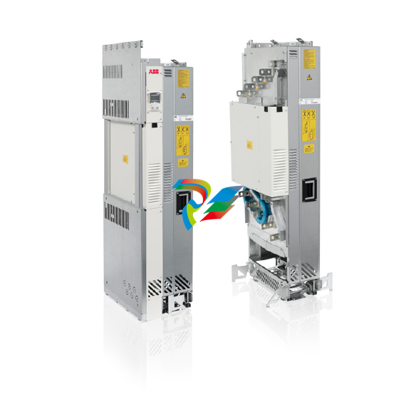
The ACS850-04 is a drive module designed for controlling asynchronous AC induction motors, permanent magnet motors, and ABB synchronous reluctance motors (SynRM motors). Its main circuit comprises an AC choke, rectifier, DC link, inverter, and an optional brake chopper (+D150) that dissipates surplus energy to a brake resistor during deceleration.
The standard unit features:
Lifting lugs and fastening brackets for installation.
Input and output cable connection busbars.
A circuit board compartment.
Main cooling fans.
Retractable support legs.
A control unit (JCU) with slots for optional I/O extension, encoder/resolver interface, and fieldbus adapter modules.
Optional selections include cabling panels (+H381 or +H383), DC busbars (+H356), various control panel and control unit configurations (e.g., +J400, +J410, +P905 for internal control unit), fieldbus adapter modules (e.g., PROFIBUS DP, PROFINET IO), I/O extension modules, and specialized control programs (e.g., Crane control program, SynRM control program).
Planning the Cabinet and Electrical Installation
Detailed guidance is provided for cabinet installation and electrical connections:
Cabinet Requirements: Use a sturdy cabinet that protects against contact, meets dust and humidity requirements, and has sufficient air inlet/outlet gratings for cooling.
Layout Planning: Design a spacious layout for easy installation and maintenance, considering cooling air flow, clearances, and cable support structures. Control boards should be placed away from main circuit components and hot parts.
Grounding: Ensure proper grounding of the drive module to the cabinet's PE busbar, either through fastening points or a separate grounding conductor.
EMC Planning: Minimize holes in the cabinet, ensure good galvanic connection between steel panels (welding or conductive EMC strips), and use 360° high-frequency grounding for cable shields at lead-throughs to suppress electromagnetic disturbances.
Cooling: Ensure sufficient ventilation of the installation site, adequate free space around components, and proper air inlet/outlet design to prevent hot air recirculation.
Cable Selection and Routing: Dimension input power and motor cables according to local regulations, using symmetrical shielded motor cables. Route motor cables away from other cable routes, crossing at right angles if necessary. All control cables must be shielded.
Protections: Install a hand-operated input disconnecting device. Protect the drive and input power cable with fuses (ultrarapid aR fuses or UL-recognized Class T/L fuses). The drive protects the motor cable and motor against short-circuits and thermal overload. For multiple motors, use separate circuit breakers/fuses for each motor.
Motor Compatibility: Use asynchronous AC induction motors, permanent magnet motors, or ABB SynRM motors. Ensure motor insulation system withstands maximum peak voltage at motor terminals, and consider optional du/dt filters, common mode filters (+E208), or insulated N-end bearings for protection.
Safety Functions: Implement Emergency Stop, Safe Torque Off, and ATEX-certified Safe Motor Disconnection functions as required.
Bypass Connection: If bypassing is needed, use mechanically or electrically interlocked contactors to prevent simultaneous closure. Never connect supply power to drive output terminals directly.
Brake Resistors: For high-capacity braking, optional brake choppers (+D150) and external resistors can be used. Select components based on braking power and heat dissipation capacity. Resistors must be installed outside the drive module in a well-cooled, non-flammable area.
-
 HIRSCHMANN MAR1040-4C4C4C4C9999SMMHPHH Managed Etherne
 -
 HIRSCHMANN MAR1040-4C4C4C4C9999SM9HRHH Managed Etherne
 -
 HIRSCHMANN MAR1040-4C4C4C4C9999SM9HPHH05.1.00 industrial switch
 -
 HIRSCHMANN MM20-P9P9M2T1SAHH Fast Ethernet media module
 -
 HIRSCHMANN MM20-P9T1T1T1SAHH hot-swappable hybrid media module
 -
 HIRSCHMANN MM20-Z6Z6T1M2SAHH Fast Ethernet media module
 -
 HIRSCHMANN MM20-Z6M2M2T1SAHH Fast Ethernet media module
 -
HIRSCHMANN MM20-Z6Z6Z6T1SAHH media module.
-
 HIRSCHMANN MM20-Z6T1T1T1EBH Fast Ethernet media card.
 -
 Hirschmann MM20-Z6T1T1T1SAHH Hot-swappable fast Ethernet media module
 -
 Hirschmann MM20-Z6Z6M2M2EBH media module
 -
 HIRSCHMANN MM20-Z6Z6T1T1SZHH Technical Datasheet & SEO Guide
 -
 HIRSCHMANN MM20-Z6Z6T1T1EBH Technical Datasheet & Overview
 -
 HIRSCHMANN MM20-Z6Z6Z6Z6SZHH Media Module
 -
 HIRSCHMANN MM20-M4M2M2T1SAHH Media Module
 -
.png) HIRSCHMANN MM20-M4T1M2T1SAHH Media Module
HIRSCHMANN MM20-M4T1M2T1SAHH Media Module -
 HIRSCHMANN MM20-M2M2T1T1EBH Media Module
 -
HIRSCHMANN MM20-M2M2T1T1SAHH Media Module
-
HIRSCHMANN MM20-M2T1T1T1TAHH Media Module
-
HIRSCHMANN MM20-M2T1T1T1EBH Media Module
-
 HIRSCHMANN MM20-M2T1T1T1SAHH Media Module
 -
 HIRSCHMANN MM20-M2M2M2M2EBH Industrial Ethernet Media Module
 -
HIRSCHMANN RS20-1600S2S2SDAEHH09.0.14 Ethernet switch
-
 HIRSCHMANN MSM20-M2M2T1T1SY9HH9E99.9.99
 -
HIRSCHMANN MSM20-M2M2M2M2SY9HH9E Ethernet media modul
-
 HIRSCHMANN SPIDER-PL-20-05T1999999TWVHHHH Industrial Ethernet Rail Switch
 -
 Hirschmann SPIDER-PL-20-07T1M2M299TWVHHHH Industrial ETHERNET Rail Switch
 -
Hirschmann (Belden) RS20-1600M2M2SDAEHC09.1.00 DIN-rail managed industrial Fast Ethernet switch
-
 Hirschmann (Belden) RS30-1602O6O6TDAPHC09.1.00 DIN-rail managed industrial Ethernet switch
 -
 Hirschmann (Belden) RS30-2402O6T1SDAPHH09.0.13 DIN-rail industrial Ethernet switch
 -
Hirschmann (Belden) SPIDER-PL-20-04T1S29999TY9HHHH Ethernet DIN-rail switch
-
 HIRSCHMANN RS20-1600T1T1SDAUHX Switch
 -
 HIRSCHMANN BRS42-0012OOOO-SPCZ99HHSES industrial switch
 -
 Hirschmann RS20-0800S2S2TDHPHH09.0.14 Fast Ethernet DIN rail switch.
 -
HIRSCHMANN MM20-Z6Z6M2M2SAHH Hybrid Fast Ethernet Media Module
-
HIRSCHMANN MM20-Z6Z6T1T1SAHH hot-swappable hybrid Fast Ethernet Media Module
-
 HIRSCHMANN MM20-P9P9T1T1SAHH Hybrid Fast Ethernet Media Module
 -
 HIRSCHMANN MM20-M4T1T1T1SAHH Hybrid Fast Ethernet Media Module
 -
HIRSCHMANN MM20-M4M4T1T1SAHH Hybrid Fast Ethernet Media Module
-
 HIRSCHMANN MM20-M2M2M2M2SZHH Ethernet media module
 -
HIRSCHMANN MM20-M2M2M2M2SAHH Ethernet media module
-
 HIRSCHMANN MM20-T1T1T1T1EBH 4-port Fast Ethernet Copper Cable Media Module
 -
HIRSCHMANN MM20-T1T1T1T1SAHH 4-port Fast Ethernet Copper Cable Media Module
-
HIRSCHMANN MM20-Z6Z6EBH Hot-swappable fast Ethernet media module
-
HIRSCHMANN MM20-Z6Z6SAHH Ethernet media module
-
HIRSCHMANN MM20-Z6Z6Z6Z6EBH Industrial Media Module
-
 MSM40-T1T1T1TZ9HH9E99.9.99 HIRSCHMANN Switch
 -
 HIRSCHMANN MS20-0800SAAEHC / MS20-0800SAAEHC0 8-port modular Layer 2 management Ethernet switch
 -
 Hirschmann RSPM20-4T14T1SZ9HHS9 Switch RSPM20-4T14T1SZ9HHS9
 -
 HIRSCHMANN RS20-1600M2M2SDAEHH09.1. RS20/30/40 Managed Switch configurator
 -
HIRSCHMANN RS20-1600M2M2SDAEHX09.0.00 Ethernet switch
-
 HIRSCHMANN BELDEN SPIDER-PL-20-07T1M2M299TY9HHHH / SPIDERPL2007T1M2M299TY9HHHH
 -
HIRSCHMANN MM3-1FXS2/3TX1 Switching Board Module
-
HIRSCHMANN RSPE30-24044O7T99-ECCP999HHSE2A08.1.00 Industrial-grade fanless management-type Ethernet switch
-
 HIRSCHMANN RS30-1602OOZZSDAEHC09.1.00 DIN-rail-mounted managed Layer 2 Ethernet switch
 -
 HIRSCHMANN MACH104-20TX-F Managed 24-port Full Gigabit 19" Switch
 -
 HIRSCHMANN Switch RS20-0800M4M4SDAE
 -
Hirschmann RS30-1602O6O6SDAEHH09.1. Management-type Ethernet switch
-
 Hirschmann RS30-1602OOZZSDAEHC09.0.10 Open rack-style Ethernet switch
 -
 HIRSCHMANN RSPE30-24044O7T99-SCCV999HHSI2SXX.X.XX High-Availability Seamless Redundancy
 -
HIRSCHMANN RSPE30-24044O7T99-SCCZ999HHSE2A DIN-rail Ethernet switch
-
HIRSCHMANN MM2-4TX1-EEC switch
-
HIRSCHMANN MSM40-T1T1T1T1TZ9HH9E99.9.99 Module
-
 HIRSCHMANN RS20 Rail Switch RS20-0400S4T1SDAEHC07.1.01
 -
 HIRSCHMANN M4-FAST8-SFP Fast Ethernet media module
 -
 HIRSCHMANN RS20-0400M2T1SDAP Managed Fast-Ethernet-Switch
 -
 HIRSCHMANN BELDEN SPIDER II 8TX/1FX EEC Industrial Ethernet Rail Switch
 -
HIRSCHMANN MM3-2FXS2/2TX1
-
 HIRSCHMANN RS2-4TX/1FX EEC Industrial Ethernet Rail Switch
 -
 RS30-0802O6O6SDAEHC09.0.10 HIRSCHMANN Switch
 -
 HIRSCHMANN m4-8TP-RJ45 Ethernet Media Module
 -
 HIRSCHMANN MSP30-24040SCZ9URHHE3A switch
 -
 Hirschmann rack MS30-1602SAAPHC
 -
 HIRSCHMANN RS2-FX/FX Industrial Switch Module
 -
Rs1txfx - Hirschmann - Rs1-Tx/Fx Rail Switch
-
RS20-0800S2S2SDAEHC09.1.00 HIRSCHMANN Commutator
-
 Hirschmann EAGLE20 TX/TX Industrial Security Router
 -
 Hirschmann SPIDER-SL-20-04T1S29999SY9HHHH Industrial Switch
 -
 HIRSCHMANN MAR1040-4C4C4C4C9999SMMHRHHXX.X. Gigabit Ethernet Switch configurator
 -
 Hirschmann MAR1040 Industrial Switch
 -
 HIRSCHMANN BELDEN RS30-1602O6O6SDAE
 -
Hirschmann RS20-1600M2M2SDAUHC Ethernet DIN rail switch
-
 HIRSCHMANN OCTOPUS 24M industrial switch
 -
HIRSCHMANN RS20-1600T1T1SDAE Management-type Ethernet switch
-
HIRSCHMANN RS20-1600T1T1SDAUHH industrial switch
-
HIRSCHMANN RS20-0800M2M2SDAPHC09.0.04 switch
-
 Hirschmann MR 8-03 24V DC Industrial Modular Bridge/Router
 -
 HIRSCHMANN RS20-0400M2T1SDAPHC08.0.01 Managed Switch
 -
 MACH1130 Hirschmann Industrial Switch
 -
 HIRSCHMANN 943824-002 SPIDER 5TX Industrial Ethernet Switch
 -
HIRSCHMANN RS30-0802O6O6SDAEHC09.1.00 Managed Industrial Switch
-
 HIRSCHMANN RS20-0400M2M2TDAEHC04.0.01 Industrial Switch
 -
 HIRSCHMANN BRS20-0600Z6Z6-STCZ99HHSES Industrial Switch
 -
 HIRSCHMANN MACH104-20TX-FR-L3P Industrial Ethernet Switch
 -
 HIRSCHMANN RS40-0009CCCCEDBPHH06.0.01 Industrial Switch
 -
HIRSCHMANN RS2-3TX/2FX EEC Industrial Ethernet Switch
-
 Hirschmann MACH 1020/1030 Fast/Gigabit Rack Mount Switches
 -
HIRSCHMANN RS20-0800M2M2SDAPHC09.0.14 Industrial Switch
-
 HIRSCHMANN RS20-1600T1T1SDAEHC09.0.04 Industrial Switch
 -
 HIRSCHMANN RSB20-0800T1T1EAABHH Industrial Switch
 -
HIRSCHMANN MACH4002-48+4G-L3E Industrial Backbone Switch
-
 HIRSCHMANN RS20-0400S2T1SDAE Industrial Managed Switch
 -
HIRSCHMANN RS20-0800S2T1SDAUHC Industrial Switch
-
HIRSCHMANN RS20-2400S4S4SDAEHC09.0.14 industrial switch
-
 HIRSCHMANN OS20-001200T5T5T5- TBBZ999HHNE3S 08.1.00 industrial switch
 -
HIRSCHMANN OS20-001200T5T5T5- TBBZ999HHNE3S 08.1.00 industrial switch
-
 HIRSCHMANN RS40-0009CCCCSDAEHH09.0.14 switch
 -
Hirschmann RS20-1600T1T1SDAUHC Management-type Ethernet Switch
-
 Hirschmann M1-8SFP Switche
 -
Hirschmann Industrial Ethernet Ruggedized Switch MACH1000 Family
-
 Basler Electric, Solid State Protective Relay, BE1-60
 -
BASLER ELECTRIC SR4A-2B15B3A Static Voltage Regulator
-
.png) BASLER ELECTRIC EXCITER DIODE MONITOR EDM-200
BASLER ELECTRIC EXCITER DIODE MONITOR EDM-200 -
.png) BASLER ELECTRIC DECS125-15-B2C5 DIGITAL EXCITATION CONTROL SYSTEM V 2.0.9
BASLER ELECTRIC DECS125-15-B2C5 DIGITAL EXCITATION CONTROL SYSTEM V 2.0.9 -
 BASLER ELECTRIC BE1-851 OVERCURRENT PROTECTION RELAY MECHANISM
 -
 Basler Electric BE1-51A / BE151A
 -
 Basler Electric BE1-40Q Loss of Excitation Relay
 -
 Basler Electric BE1-87G Variable Percentage Differential Relay
 -
 Basler Electric BE1-11 Protection System I5A3M2P2N0EA00
 -
 BASLER ELECTRIC DECS-200-1C Digital Excitation Control System
 -
 Basler Electric / Kohler BE1-11g Generator Protection Relay G5A3M2J2N0E000
 -
BASLER ELECTRIC DECS125-15 DIGITAL EXCITATION CONTROL SYSTEM
-
 BASLER ELECTRIC BE1-951 OverCurrent Protecton System
 -
Basler Electric DECS-200-1L Digital Excitation Control System
-
 Basler Electric DGC-2020HD-5NS1DNSBA Digital Genset Controller -
 -
 BASLER ELECTRIC BE1-81T1EE1WA0N1F / BE181T1EE1WA0N1F
 -
 BASLER ELECTRIC BE1-25M1EA6PN5R1F / BE125M1EA6PN5R1F
 -
 BASLER ELECTRIC DECS-250-LN1SN1N DIGITAL EXCITATION CONTROL SYSTEM


