
ABB ACS850-04 Drive Modules: Hardware Manual Summary
ABB ACS850-04 Drive Modules: Hardware Manual Summary
This document serves as the hardware manual for ABB ACS850-04 drive modules, covering models from 160 to 560 kW (200 to 700 hp). It provides essential information for planning, installation, operation, maintenance, and technical specifications, ensuring safe and efficient use of the drive modules.
Introduction and Safety Instructions
The manual is intended for personnel involved in planning cabinet assembly, electrical installation, and providing end-user instructions for mechanical installation, cabling, and maintenance. It emphasizes strict adherence to safety instructions to prevent physical injury, death, or damage to equipment. Key safety warnings include:
Only qualified electricians are permitted to install and maintain the drive.
Always disconnect main power and wait 5 minutes for capacitors to discharge before working on the drive, motor, or motor cable.
Verify zero voltage with a multimeter before commencing work.
Do not work on control cables when power is applied to the drive or external control circuits.
Avoid insulation or voltage withstand tests on the drive.
Be aware of dangerously high voltages on motor cable and brake control terminals.
The Safe Torque Off function does not remove voltage from main and auxiliary circuits.
Proper grounding of the drive, motor, and adjoining equipment is crucial for safety and EMC.
For permanent magnet motors, ensure the motor cannot rotate and disconnect it before working on the drive, as a rotating PM motor can energize the drive's intermediate circuit.
Handle the heavy drive module carefully using lifting lugs and support legs to prevent overturning.
Beware of hot surfaces on heatsinks.
Prevent dust from entering the drive during installation.
Handle fiber optic cables by the connector, not the cable itself, and avoid touching fiber ends.
Wear a grounding wrist band when handling printed circuit boards due to their sensitivity to electrostatic discharge.
Do not run the motor over its rated speed, as overvoltage can damage or explode capacitors.
Ensure the motor and driven equipment are suitable for the drive's full speed range before operation.
Avoid activating automatic fault reset functions if dangerous situations can occur.
Control the motor using the control panel keys or I/O board commands, not an AC contactor.
Product Overview and Hardware Description
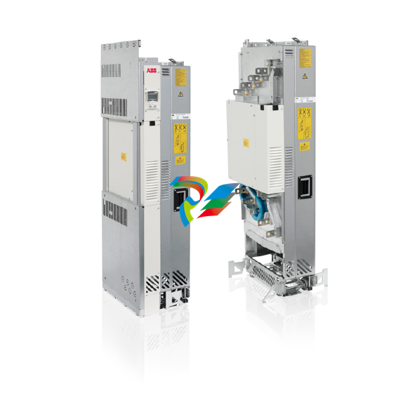
The ACS850-04 is a drive module designed for controlling asynchronous AC induction motors, permanent magnet motors, and ABB synchronous reluctance motors (SynRM motors). Its main circuit comprises an AC choke, rectifier, DC link, inverter, and an optional brake chopper (+D150) that dissipates surplus energy to a brake resistor during deceleration.
The standard unit features:
Lifting lugs and fastening brackets for installation.
Input and output cable connection busbars.
A circuit board compartment.
Main cooling fans.
Retractable support legs.
A control unit (JCU) with slots for optional I/O extension, encoder/resolver interface, and fieldbus adapter modules.
Optional selections include cabling panels (+H381 or +H383), DC busbars (+H356), various control panel and control unit configurations (e.g., +J400, +J410, +P905 for internal control unit), fieldbus adapter modules (e.g., PROFIBUS DP, PROFINET IO), I/O extension modules, and specialized control programs (e.g., Crane control program, SynRM control program).
Planning the Cabinet and Electrical Installation
Detailed guidance is provided for cabinet installation and electrical connections:
Cabinet Requirements: Use a sturdy cabinet that protects against contact, meets dust and humidity requirements, and has sufficient air inlet/outlet gratings for cooling.
Layout Planning: Design a spacious layout for easy installation and maintenance, considering cooling air flow, clearances, and cable support structures. Control boards should be placed away from main circuit components and hot parts.
Grounding: Ensure proper grounding of the drive module to the cabinet's PE busbar, either through fastening points or a separate grounding conductor.
EMC Planning: Minimize holes in the cabinet, ensure good galvanic connection between steel panels (welding or conductive EMC strips), and use 360° high-frequency grounding for cable shields at lead-throughs to suppress electromagnetic disturbances.
Cooling: Ensure sufficient ventilation of the installation site, adequate free space around components, and proper air inlet/outlet design to prevent hot air recirculation.
Cable Selection and Routing: Dimension input power and motor cables according to local regulations, using symmetrical shielded motor cables. Route motor cables away from other cable routes, crossing at right angles if necessary. All control cables must be shielded.
Protections: Install a hand-operated input disconnecting device. Protect the drive and input power cable with fuses (ultrarapid aR fuses or UL-recognized Class T/L fuses). The drive protects the motor cable and motor against short-circuits and thermal overload. For multiple motors, use separate circuit breakers/fuses for each motor.
Motor Compatibility: Use asynchronous AC induction motors, permanent magnet motors, or ABB SynRM motors. Ensure motor insulation system withstands maximum peak voltage at motor terminals, and consider optional du/dt filters, common mode filters (+E208), or insulated N-end bearings for protection.
Safety Functions: Implement Emergency Stop, Safe Torque Off, and ATEX-certified Safe Motor Disconnection functions as required.
Bypass Connection: If bypassing is needed, use mechanically or electrically interlocked contactors to prevent simultaneous closure. Never connect supply power to drive output terminals directly.
Brake Resistors: For high-capacity braking, optional brake choppers (+D150) and external resistors can be used. Select components based on braking power and heat dissipation capacity. Resistors must be installed outside the drive module in a well-cooled, non-flammable area.
Installation and Start-up
The installation process involves:
Installing mechanical accessories into the cabinet.
Installing auxiliary components.
Connecting power cables to cabling panels.
Mounting the drive module into the cabinet.
Mounting the external control unit (if applicable).
Connecting control cables.
Installing remaining cabinet parts.
A detailed installation checklist is provided to ensure all mechanical and electrical aspects are correctly installed and tightened. Before start-up, verify the installation checklist, ensure the motor and driven equipment are ready, switch on power, set up the drive control program, and validate the Safe Torque Off function.
Maintenance and Technical Data
The manual outlines routine maintenance intervals, including annual checks for fans, terminal tightness, dust, corrosion, and supply voltage quality. Capacitors require reforming if the drive has been stored for a year or more. Periodical replacement of cooling fans, DC circuit electrolytic capacitors, and certain circuit boards is recommended.
Key technical data includes:
Ratings: Detailed input and output ratings for nominal, light-overload, and heavy-duty use across various voltage ranges.
Derating: Guidelines for derating continuous output currents based on ambient temperature (above 40°C) and altitude (above 1000m).
Fuses: Recommended ultrarapid (aR) fuses (IEC) and UL recognized Class T/L fuses.
Dimensions and Weights: Physical dimensions and weights of drive modules, with and without optional components.
Losses, Cooling Data, and Noise: Air flow, heat dissipation, and noise levels for different drive types.
Cable Data: Terminal and lead-through data for power and control cables, including recommended cable sizes and tightening torques.
Electrical Power Network Specification: Voltage, frequency, imbalance, and power factor requirements.
Motor Connection Data: Supported motor types, voltage, frequency, current, and maximum recommended motor cable lengths for DTC and scalar control.
Brake Resistor Connection Data: Ratings and connection details for brake resistors.
DC Connection Data: Current and capacitance for common DC configurations.
Control Unit (JCU-11) Connection Data: Specifications for power supply, relay outputs, digital inputs/outputs, analog inputs/outputs, drive-to-drive link, and Safe Torque Off connection.
Efficiency: Approximately 98% at nominal power level.
Degree of Protection: IP00 (UL type open), or IP20 with option +H381.
Ambient Conditions: Environmental limits for operation, storage, and transportation, covering temperature, humidity, contamination levels, atmospheric pressure, vibration, and shock.
Materials and Applicable Standards: Details on drive enclosure materials, recycling guidelines, and compliance with various international standards (e.g., EN 61800-5-1, EN 60204-1, UL 508C, CSA C22.2 No. 14-10, GOST R 51321-1).
CE Marking: Confirms compliance with European Low Voltage, EMC, and Machinery Directives (for safety functions).
EMC Compliance: Details for Category C3 and C4 drives, including provisions for meeting EMC requirements.
UL and CSA Marking: Information on UL and CSA listings and associated checklists.
This manual serves as a critical resource for anyone involved with the ABB ACS850-04 drive modules, providing comprehensive guidance from initial planning to long-term maintenance.
-
 Applied Materials (AMAT) 0190-04098 | 5.X Factory Interface I/O Distribution Board
 -
 Applied Materials (AMAT) 0190-03705 | MF Producer SE/E Interlock Module
 -
 Applied Materials (AMAT) 0190-02748 | Flex Scanner Transition Module
 -
 Applied Materials (AMAT) 0190-02362 | Mainframe Interlock 1 Relay Module
 -
 Applied Materials (AMAT) 0190-01227 | Intelligent Motor Control OMS Board
 -
 Applied Materials (AMAT) 0190-00318 | VME 486 Video Controller
 -
 Applied Materials (AMAT) 0130-14007 | Advanced RF Signal Assembly
 -
 Applied Materials (AMAT) 0130-14005 | RF Cable/Interface Assembly
 -
 Applied Materials (AMAT) 0130-01218 | High-Efficiency RF Interface Controller
 -
 Applied Materials (AMAT) 0110-77040 | Head Pneumatic Controller
 -
 Applied Materials (AMAT) 0110-00077 | Precision Control Module
 -
 AMAT 0101-57015 high-performance Next-Generation Deflection Amplifier Board
 -
 AMAT 0100-77040 critical Head Pneumatic Controller Board
 -
 AMAT 0100-76291 Data Buffer / Memory Expansion Interface
 -
 AMAT 0100-76290 Advanced I/O Interface Board
 -
 AMAT 0100-76269 Control Board / Interface Module
 -
 AMAT 0100-71462-01 high-performance Process Controller PCB
 -
 AMAT 0100-71171 Chamber Interlock Control PCB
 -
 AMAT 0100-71154 Semiconductor Circuit Board / Electronic Group Card
 -
 AMAT 0100-70034 PCB Assembly (PCBA) for Endpoint VGA I/O Interconnect.
 -
 AMAT 0100-38032 ESC (Electrostatic Chuck) Controller PCB
 -
 AMAT 0100-36035 DPS Source Match / Seriplex I/O Distribution PCB
 -
 AMAT 0100-35231 Seriplex I/O Distribution Module
 -
 AMAT 0100-35217 TC Amp Interlock PCB Module
 -
 AMAT 0100-35065 High-Precision Serial Isolator PCB
 -
 AMAT 0100-35054 Advanced Chamber Interface Module
 -
 AMAT 0100-20453 DeviceNet Digital I/O Interface Board
 -
 AMAT 0100-20100 High-Performance Semiconductor Component
 -
 AMAT 0100-20068 Precision CCD Image Control Board
 -
 AMAT 0100-20064 Advanced Semiconductor Control Module
 -
Applied Materials (AMAT) 0100-20018 Advanced Communication Interface Module
-
 Applied Materials (AMAT) 0100-20016 High-Performance Interface and Control Module
 -
 Applied Materials (AMAT) 0100-20003 Digital I/O (DI/DO) Interface Board
 -
 Applied Materials (AMAT) 0100-20001 System Electronics Interface (SEI) / PCB Assembly
 -
 Applied Materials (AMAT) 0100-11030 Chamber Hardware / Gas Distribution Component
 -
 Applied Materials (AMAT) 0100-11022 Semiconductor Board Card
 -
 Applied Materials (AMAT) 0100-11018 Advanced Interface Control Module
 -
 Applied Materials (AMAT) 0100-11001 Precision Analog Output Board
 -
 Applied Materials (AMAT) 0100-11000 High-Precision Analog Input Board
 -
 Applied Materials (AMAT) 0100-09237 Advanced Signal Interface Module
 -
 Applied Materials (AMAT) 0100-09204 Advanced Digital Interface Control Board
 -
 Applied Materials (AMAT) 0100-09172 High-Density Digital I/O Control Board
 -
 Applied Materials (AMAT) 0100-09137 High-Performance VME Control Module
 -
 Applied Materials (AMAT) 0100-09054 Precision Analog Input Board
 -
 Applied Materials (AMAT) 0100-09029 Turbo Interconnect Interface Module
 -
 AMAT 0100-03391 Precision Semiconductor Control
 -
 AMAT 0100-01984 | VME System Interface & Logic Controller Board
 -
 AMAT 0100-01363 | VME Intelligent System Control & I/O Board
 -
 AMAT 0100-01321 | VME DeviceNet Scanner / Interface Board
 -
AMAT 0100-00793 | VME Multi-Channel Interface & Logic Board
-
 AMAT 0100-00689 | VME PCB Power Module
 -
 AMAT 0100-00580 | VME Intelligent System Controller Board
 -
 AMAT 0100-00523 | VME Multi-Channel Analog-to-Digital (A/D) Board
 -
 AMAT 0100-00493 | VME Multi-Function System Controller Board
 -
 AMAT 0100-00398 | VME Interface System Control Board
 -
 AMAT 0100-00369 | VME 12-Channel High-Speed Stepper Motor Controller
 -
 AMAT 0100-00196 | VME System Mainframe CPU Controller Board
 -
 AMAT 0100-00169 | VME 12-Channel Stepper Motor Controller Board
 -
 AMAT 0100-00162 | VME Dual Channel Serial Communication Board
 -
 AMAT 0100-00137 | VME Stepper Motor Controller Interface Board
 -
 AMAT 0100-00075 | VME Digital Input/Output (DI/O) Interface Board
 -
 AMAT 0100-00007 VME Analog Input/Output Interface Board
 -
 AMAT 0100-00002 | VME Slave I/O Interface PCB
 -
 AMAT 0090-05596 High-Voltage DC Power Cable Assembly
 -
 AMAT 0090-01809 | High-Performance RF Power Cable Assembly
 -
 AMAT 0010-29958 | CCM HART 3 Mainframe Control Assembly
 -
 AMAT 0010-20003 System Controller Card Cage Assembly
 -
.png) AMAT 0010-11239 PVD High-Voltage Power Interface Assembly
AMAT 0010-11239 PVD High-Voltage Power Interface Assembly -
 AMAT 0010-09416 RF Matching Network Assembly
 -
 AMAT 0010-00019 Analog Power Supply Assembly
 -
 AMAT AS00009-02 (31-000-00940) | Precision Semiconductor Component
 -
 AMAT 0010-00028 Power Supply Module
 -
 AMAT 0330-1586A Serial Communication PCB
 -
 AMAT 0190-09690 Seriplex SENSORbus SPX-MUXADIO-001
 -
 AMAT 0190-04397 DeviceNet I/O Interface Board
 -
 AMAT 0190-02506 DeviceNet I/O Interface Card
 -
 AMAT 0090-00475 Seriplex 210 MUXADIO
 -
 AMAT 410-0198-1 Multi-Output Switching Power Supply
 -
 AMAT 0100-20458 high-reliability Configurable Interlock Personality Board
 -
 AMAT VAS104350-0415 Gasline Heater Control Unit
 -
 AMAT VME6U1V2 VMEbus Backplane Interface Module
 -
AMAT 0920-01070 high-performance RF Power Generator
-
 AMAT 0090-76133A VME Single Board Computer (SBC)
 -
 AMAT 0190-24115 DeviceNet I/O Interface Card
 -
 AMAT 0190-37607 Backplane / Base Board Assembly
 -
 AMAT 0190-32372 Analog Input/Output (I/O) Board
 -
 AMAT 0190-09956 Loadlock Interface PCB Base Assembly
 -
 AMAT 0190-07908 four-channel DeviceNet Interface Card
 -
 AMAT 0190-07905 (UPS) control board
 -
 AMAT 0190-07502 Precision Controller / Interface Board
 -
 AMAT 0190-03680 I/O Backplane
 -
 AMAT 0190-02200 Water Leak Detection Control Board
 -
 AMAT 0100-76124 Digital I/O Board Assembly
 -
 AMAT 0100-35563 Leak Detector Configuration PCB
 -
 AMAT 0100-35250 Chamber Interface DPS Centura PCB
 -
 AMAT 0100-35124 Seriplex I/O Distribution Board
 -
 AMAT 0100-35058 Loadlock Interlocks PCB
 -
 AMAT 0100-20213 RF Match Detector PCB
 -
 AMAT 0100-20063 Interface PCB Assembly
 -
 AMAT 0100-09225 TC AMP/INTERLOCK PCB
 -
 AMAT 0100-09153 Gas Panel Interface PCB
 -
 AMAT 0100-09127 Loader Interconnect Board
 -
 AMAT 0100-09009 Buffer I/O PCB Card
 -
 AMAT 0100-02813 Signal Conditioning Board
 -
 AMAT 0100-01911 AC Gas Heater Control Board
 -
 AMAT 0100-01708 Pedestal Integration PCB
 -
 AMAT 0100-00658 300mm RTP Controller Distribution PCB
 -
 AMAT 0100-00582 Gas Panel Controller Backplane
 -
 AMAT 0100-00049 Analog Signal Conditioner
 -
 AMAT 0100-00008 Control Interface Module
 -
 AMAT 0090-03402 DC Power Supply / Power Module
 -
 AMAT 0090-01248 DC Power Supply / Power Module
 -
 AMAT 0090-76109 RF Matching / Capacitor Assembly
 -
 AMAT 0101-57106 Substrate Voltage Board
 -
 AMAT 0101-57014 Deflection-Amplifier PCB
 -
 AMAT 0101-57012 AKT Column Control PCB (COL-C 50-10)
 -
 AMAT AKT 0241-58482 PCB
 -
 AMAT 0241-58255 REV05 PCB
 -
 AMAT 0161-57042 AKT framework
 -
 AMAT 0101-57196 electronic control board
 -
 AMAT 0101-57178 Digital Input / Interface PCB
 -
 AMAT 0101-57162 electronic control board
 -
 AMAT 0101-57127 P-DRV (Power Driver Board)
 -
 AMAT 0101-57126 D-AMP 50-06 (Digital/Analog Amplifier)
 -
 AMAT 0101-57125 AKT COL-C Communication Board
 -
AMAT 0101-57120 D-OUT 50-32 (Digital Output Board)
-
 AMAT 0101-57112 D-IN 50-32 (Digital Input Board)
 -
 AMAT 0101-57102 electronic control board


