
Functional Features
Dual-Channel Redundant Design: Utilizes dual-channel monitoring. When one channel fails, the other can continue to operate normally, ensuring uninterrupted operation and enhancing system reliability and stability.
Intelligent Alarm System: Capable of real-time signal status monitoring. Once an abnormal condition is detected, it can immediately notify the operator so that prompt action can be taken to prevent the fault from escalating and to minimize downtime.
Configurable Limit Settings: Each channel features adjustable upper and lower limit settings. Users can flexibly define the normal range of analog signals according to specific application requirements, enabling precise monitoring and control.
High-Precision Monitoring: Equipped with high-accuracy detection capabilities, it can accurately identify minor deviations in analog signals and respond quickly, ensuring the accuracy and safety of process control.
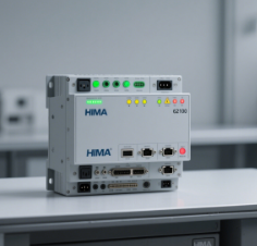
# HIMA 62100: Usage Methods and Precautions HIMA 62100 is an analog current limit monitor. Below are its usage methods and precautions: ## Usage Methods 1. **Installation and Connection**: Install the HIMA 62100 in a suitable location based on the actual application scenario, ensuring stable mounting. Correctly connect the analog signal sources to be monitored (such as voltage or current signals output by temperature, pressure sensors, etc.) to the device’s input ports. Ensure connections are secure to avoid signal interruptions. 2. **Parameter Configuration**: Enter the parameter setting mode through the device’s operation interface or related configuration software. Set upper and lower threshold limits for each channel according to specific monitoring requirements to define the normal operating signal range. Meanwhile, configure output modes, alarm parameters, etc., as per system requirements. 3. **Operation Monitoring**: After configuration, put the device into operation. The device will monitor input analog signals in real-time. When the signal value exceeds the set upper or lower limits, it will issue alarm signals in the preset manner, such as lighting up alarm indicators or outputting alarm currents. 4. **Status Checking and Maintenance**: Regularly check the device’s operating status. Use indicators, displays on the device, or connect to upper-level software to check for fault prompts, signal abnormalities, etc. If anomalies are found, promptly troubleshoot and handle them based on the information provided by the device. Additionally, perform maintenance operations such as cleaning and calibration as needed. ## Precautions - **Power Supply Requirements**: Use the dedicated power cord or adapter specified for the device. Confirm that the supply voltage matches the voltage marked on the device’s power interface to avoid equipment damage due to voltage abnormalities. - **Installation Environment**: Install the device in a well-ventilated environment free from strong vibrations, strong electromagnetic interference, and with moderate temperature and humidity. The operating temperature should generally be below 40°C to ensure the device’s normal performance and service life. - **Safe Operation**: Do not open the device casing during operation. Non-professionals must not open it by themselves to prevent electric shock hazards. Always cut off the power supply before performing installation, wiring, maintenance, or other operations. - **Signal Connection**: Ensure input signal connections are correct and secure to avoid signal interference. If signal quality is poor, take anti-interference measures such as using shielded wires and proper grounding. - **Regular Calibration**: To ensure monitoring accuracy, calibrate the device regularly. Follow the instructions in the device manual, use standard signal sources for calibration, or have it calibrated by professionals. - **Fault Handling**: If the device exhibits symptoms such as smoking, abnormal noises, or unusual odors, immediately cut off the power supply and unplug the power plug. Only restart the device after troubleshooting and confirming it is normal.
# HIMA 62100 Technical Parameter Details
As a highly reliable analog current limit monitor, the technical parameters of HIMA 62100 cover key dimensions such as input, output, performance, and environmental adaptability. Below is a detailed description:
## I. Input Parameters
- **Input Type**: Supports standard analog signal input, including
- Current signal: 4~20 mA (conventional industrial sensor output signal).
- Voltage signal: Optional 0~10 V or other customized voltage ranges (activation via parameter configuration is required).
- **Input Channels**: Dual-channel redundant design, supporting independent monitoring of two analog signals. Electrical isolation between channels prevents signal interference.
- **Input Impedance**: ≥ 250 Ω in current input mode; ≥ 100 kΩ in voltage input mode, ensuring minimal impact on the signal source load.
## II. Output Parameters
- **Output Type**: Alarm/control output, supporting
- Relay output: Normally closed (NC)/normally open (NO) contacts, rated load 250 V AC / 30 V DC, maximum current 2 A (resistive load).
- Current output: Each channel can be configured with 0~100 mA drive current to trigger external alarm devices or control systems.
- **Diagnostic Output**: Supports line diagnostic signal output; fault status such as wire breakage and short circuit can be read via configuration software.
## III. Performance Parameters
- **Measurement Accuracy**:
- Current signal: ±0.1% of full scale (at 25°C, within 4~20 mA range).
- Voltage signal: ±0.2% of full scale (within 0~10 V range).
- **Response Time**: ≤ 10 ms (the delay time of alarm output after the signal exceeds the threshold can be set via parameters, ranging from 0 to 1000 ms).
- **Resolution**: 16-bit AD conversion, ensuring accurate capture of tiny signal changes.
## IV. Power Supply Parameters
- **Supply Voltage**: AC 220 V ± 10% or DC 24 V ± 15% (selected according to model; the rated voltage is marked on the device nameplate).
- **Power Consumption**: ≤ 5 W during normal operation; ≤ 1 W in standby mode, suitable for integration in low-power scenarios.
## V. Environmental and Mechanical Parameters
- **Operating Temperature**: -10°C ~ +55°C (industrial-grade wide-temperature design, adapting to harsh environments).
- **Storage Temperature**: -25°C ~ +70°C.
- **Relative Humidity**: 5% ~ 95% (non-condensing), with moisture resistance.
- **Vibration Resistance**: Complies with IEC 60068-2-6 standard, 0.15 mm amplitude at 10~55 Hz frequency, 10 cycles (per axis).
- **Shock Resistance**: Complies with IEC 60068-2-27 standard, 15 g acceleration for 11 ms (half-sine wave, 3 times per axis).
- **Protection Class**: IP20 (panel-mounted part), suitable for installation in control cabinets.
- **Dimensions**: Width × Height × Depth = 22.5 mm × 100 mm × 115 mm (standard DIN rail mounting size).
## VI. Certification and Safety Parameters
- **Safety Certification**:
- Certified by TÜV, compliant with DIN V 19250 standard RC 1~6 levels.
- Complies with IEC 61508 standard, reaching SIL 3 safety integrity level, suitable for safety-critical control systems.
- **Electromagnetic Compatibility (EMC)**:
- Emission interference: Complies with EN 61000-6-4 standard.
- Immunity to interference: Complies with EN 61000-6-2 standard, resistant to electromagnetic interference in industrial environments.
## VII. Other Parameters
- **Calibration Cycle**: It is recommended to calibrate once a year, using a standard signal source (such as a 4~20 mA precision current source) to verify accuracy.
- **Display and Indication**: The panel is equipped with LED indicators, including a power light (green), a running light (yellow), and alarm lights (red, with independent indication for dual channels).
The above parameters are based on the standard model of HIMA 62100. In specific applications, details should be confirmed with the equipment manual and actual configuration.
| User name | Member Level | Quantity | Specification | Purchase Date |
|---|


-
 EMERSON AMS 2140 Machinery Health Analyzer
 -
 Hirschmann Industrial Ethernet Rail Switch RS20 Basic Family
 -
 GE Grid Solutions P40U Px40 USB Adaptor
 -
 ABB ontinuous Gas Analyzers AO2000 Series AO2040CU Ex Central Unit in Category 2G
 -
 ABB Advance Optima AO2000 Series Continuous gas analyzers Models AO2020. AO2040
 -
 Advance Optima Module Uras 14
 -
 SAACKE control optimization
 -
 SAACKE se@vis efficiency monitor
 -
 SAACKE se@vis pro
 -
 SAACKE se@vis eco
 -
 SAACKE se@vis compact
 -
 HIRSCHMANN Industrial ETHERNET Switch MICE MS20/MS30
 -
 HIRSCHMANN MICE Media modules
 -
 Kongsberg GL-10 Level Switch
 -
 B&R ACOPOSinverter P74 frequency converter
 -
 Beckhoff CX2020 | Basic CPU module (service phase)
 -
 Beckhoff CX1010 | Basic CPU module (service phase)
 -
 Beckhoff CX5120 | Embedded PC with Intel Atom® E3815
 -
 Beckhoff CP69xx-xxxx-0010 | Economy built-in Control Panel with DVI/USB Extended interface
 -
 Beckhoff CP29xx-0000 | Multi-touch built-in Control Panel with DVI/USB Extended interface
 -
 SAACKE Monoblock Rotary Cup Burner SKVJ-M
 -
 ABB Plantguard Fault Tolerant Technology Architecture and Software
 -
 OMRON H8PR-8/H8PR-8P H8PR-16/H8PR-16P H8PR-24/H8PR-24P Rotary Positioner
 -
 ABB PFSA107-Z42 DTU Stressometer Digital Transmission Unit
 -
 Nidec Mentor MP
 -
 IBA ibaNet-E
 -
 IBA FO Connection to Reflective Memory
 -
 IBA FO Connection to Siemens Systems
 -
 IBA Interface Cards For Fiber Optic Connections
 -
 IBA Field and Drive Buses
 -
 IBA ibaPADU-S Modular System
 -
 IBA ibaMAQS
 -
 STUCKE SYMAP®ARC
 -
 STUCKE SYMAP®R
 -
 STUCKE SYMAP®Compact
 -
 MOOG G123-825-001 BUFFER AMPLIFIER
 -
 Motorola MVME5100 Series VME Processor Modules
 -
 Motorola MVME162 Embedded Controller
 -
 HIMatrix Safety-Related Controller System Manual for the Modular Systems
 -
 Motorola MVME2400 Series VME Processor Module
 -
 Sieger System 57
 -
 KONGSBERG MRU product line continuation
 -
 Woodward easYgen-3100/3200 Genset Control for Multiple Unit Operation
 -
 Woodward MFR 300 Multifunction Relay / Measuring
 -
 ABB AX410, AX411, AX413, AX416, AX418, AX450, AX455 and AX456 Single and dual input analyzers for low level conductivity
 -
 ABB AX410, AX411, AX416, AX450 and AX455 Single and dual input analyzers
 -
 Woodward easYgen-1400 Technical Manual Genset Control
 -
 Woodward easYgen-400 Operation Manual Genset Control
 -
 Woodward High Output Digital Valve Positioner (DVP)DVP5000/DVP10000/DVP12000
 -
 Woodward High Output Digital Valve Positioner DVP5000 and DVP10000
 -
 Woodward TG611-13/-17 Overspeed Test Device Conversion Kit
 -
 Woodward MicroNet Safety Module (MSM)
 -
 Woodward 2301A Electronic Load Sharing and Speed Control 9905/9907 Series
 -
 Woodward-Service Bulletin 01671
 -
 UniOP eTOP40B 12.1” TFT color display
 -
 UniOP eTOP40 TFT Color display
 -
 UniOP eTOP33B 10.4” TFT color display
 -
 UniOP eTOP33C eTOP33-0050 Resistive touchscreen
 -
UniOP eTOP30. eTOP32 eTOP32-0050 Human-machine interface equipment
-
 UniOP eTOP20B and eTOP21B eTOP20B-0050
 -
 UniOP eTOP12 eTOP12-0050 Advanced human-machine interface equipment
 -
 UniOP eTOP11 eTOP11-0050 HMI
 -
 UniOP eTOP06C HMI
 -
 UniOP eTOP06 HMI
 -
 UniOP eTOP05EB eTOP05EB-DF45 HMI
 -
 UniOP eTOP05. eTOP05P Human-machine interface equipment
 -
 UniOP eTOP03 eTOP03-0046
 -
 UniOP eTOP507 507U2P1 eTOP Series 500 Human-Machine Interface
 -
 UniOP eTOP307
 -
 UniOP ETT-VGA Human-machine interface touch unit
 -
 UniOP ePAD32B, ePAD33B and ePAD33BT ePAD33B-0350
 -
 UniOP ePAD05 and ePAD06
 -
 UniOP CP02R-04 Human-machine interface
 -
 UniOP ERT-16 - Industrial PLC Workstation
 -
 UniOP ePAD03 and ePAD04
 -
 UNIOP EPALM10-DA71 state-of-the-art handheld HMI
 -
 Watlow SERIES CLS200 SPECIFICATION SHEET
 -
 Detailed Explanation of B&R Power Panel 300/400: The Core of Industrial Automation Control
 -
 YOKOGAWA Models ANB10S, ANB10D, ANR10S, ANR10D Node Units (for FIO)
 -
 Woodward ESDR 4 Current Differential Protection Relay
 -
 Woodward easYgen-3000 Genset Control for
 -
 Woodward CPC-II Current-to-Pressure Converter
 -
 Woodward 8290-189-EPG-installation-manual 8290-044
 -
 Woodward Product Change Notification 06946A
 -
 Woodward Product Change Notification 06912
 -
 Fisher™ 4660 High-Low Pressure Pilot
 -
 Flexible digital protection and control equipment SYMAP®
 -
 Woodward 723PLUS Digital Control
 -
 Woodward 505 Digital Controller For steam turbineses
 -
 Woodward 85018V2 505E Digital Governor for Extraction Steam Turbines
 -
Woodward 85018V1 Turbine Control Parameters
-
Woodward 26871 505 Enhanced Digital Control for Steam Turbines
-
 Woodward 03365 505E (Extraction / Admission)
 -
 KONGSBERG RMP420-Remote Multipurpose Input/Output
 -
 KONGSBERG RCU501 Remote Controller Unit
 -
 KONGSBERG RCU500 Remote Controller Unit
 -
 K-Gauge TOP KONGSBERG Tank Overfill Protection SystemFeatures
 -
 Kongsberg DPS112 DGNSS (DGPS/DGLONASS) sensor
 -
 Kongsberg d0000930-presafe-atex-report signed
 -
 HIMax TECHNICAL FACTS X Series
 -
 GE Multilin F650
 -
 GE MIF II - Legacy
 -
 GE PQM II Power QualIty Meter
 -
 Hydran 201Ti Mark IV Essential DGA monitoring for transformers
 -
 alstom AMS42/84 5B Amplifier SystemAmplifier Technology at its Best.
 -
 GE VMIVME-5576 Fiber-Optic Reflective Memory with Interrupts
 -
 GE Multilin 750/760 - Legacy Feeder Protection System
 -
 GE Fanuc Automation VMICPCI-7806 Specifications
 -
 VMIVME-7807 VME-7807RC* Intel® Pentium® M-Based VME SBC
 -
 GE Fanuc Automation VMIVME-7750 Specifications
 -
 FOXBORO Compact FBM240. Redundant with Readback, Discrete
 -
 FOXBORO FBM208/b, Redundant with Readback, 0 to 20 mA I/O Module
 -
 FOXBORO FBM201e Analog Input (0 to 20 mA) Interface Modules
 -
 Foxboro DCS FBM206 Pulse Input Module
 -
 FOXBORO FBM216 HART® Communication Redundant Input Interface Module
 -
 FOXBORO Z-Module Control Processor 270 (ZCP270)
 -
 FOXBORO Fieldbus Communications Module, FCM10Ef
 -
 FOXBORO Fieldbus Communications Module, FCM10E
 -
 Foxboro DCS Compact FBM241/c/d, Redundant, Discrete I/O Modules
 -
Foxboro FBM223 PROFIBUS-DP™ Communication Interface Module
-
 Foxboro DCS FBM204. 0 to 20 mAI/OModule
 -
Foxboro FBM239, Discrete 16DI/16DO Module
-
Foxboro FBM202 Thermocouple/mV Input Module
-
 Foxboro E69F Current-to-Pneumatic Signal Converter
 -
 EMERSON M-series Intrinsically Safe I/O
 -
 MVME6100 Series VMEbus Single-Board Computer
 -
 Configuration for AMS 6500 Protection Monitors
 -
 Ovation™ Controller Model OCR1100 (5X00481G04/5X00226G04)


