
ABBAO2000-LS25 Laser analyzers
1 Introduction
1.1 General This manual contains information of installation, operation and maintenance of the AO2000- LS25 Laser analyzer. A description of the analyzer and its basic features is also included. Please read sections 3 and 4 carefully before using the analyzer. It is a sophisticated instrument utilizing state-of-the-art electronic and laser technology. Installation and maintenance of the instrument require care and preparation. Failure to do so may damage the instrument and void the warranty.
1.2 Measuring principle The analyzer is an optical instrument for continuous in-situ gas monitoring in stack, pipes, process chambers or similar and is based on tunable diode laser absorption spectroscopy (TDLAS). The analyzer utilizes a transmitter/receiver configuration (mounted diametrically opposite each other) to measure the average gas concentration along the line-of-sight path. The measuring principle is infrared single-line absorption spectroscopy, which is based on the fact that each gas has distinct absorption lines at specific wavelengths. The measuring principle is illustrated in Figure 1-1. The laser wavelength is scanned across a chosen absorption line of the gas to be measured. The absorption line is carefully selected to avoid cross interference from other (background) gases. The detected light intensity varies as a function of the laser wavelength due to absorption of the targeted gas molecules in the optical path between transmitter and receiver. In order to increase sensitivity the wavelength modulation technique is employed: the laser wavelength is slightly modulated while scanning the absorption line. The detector signal is spectrally decomposed into frequency components at harmonics of the laser modulation frequency. The second harmonics of the signal is used to measure the concentration of the absorbing gas. The line amplitude and line width are both extracted from the second harmonics line shape, which makes the measured concentration insensitive to line shape variations (line broadening effect) caused by background gases. NOTE: The analyzer measures the concentration of only the FREE molecules of the specific gas, thus not being sensitive to the molecules bound with some other molecules into complexes and to the molecules attached to or dissolved in particles and droplets. Care should be taken when comparing the measurements with the results from other measurement techniques.
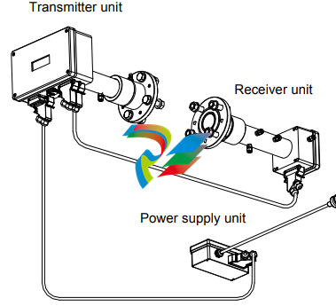
The analyzer consists of 3 separate units (see Figure 1-2):
Transmitter unit with purging
Receiver unit with purging
Power supply unit
The transmitter unit contains the laser module with a temperature stabilized diode laser, collimating optics, and the main electronics in a coated Aluminum box. The receiver unit contains a focusing lens, the photodetector and the receiver electronics in a coated Aluminum box. Both transmitter and receiver units have environmental protection IP66, and the standard optical windows withstand pressures up to 5 bar (absolute pressure). The monitor is installed by assembling the transmitter and receiver units with the supplied purging & alignment units, which in turn are mounted onto the DN50 process flanges (see Figure 3-1). The optical alignment is easy and reliable, and the purging prevents dust and other contamination from settling on the optical windows. A block diagram of AO2000-LS25 is shown in Figure 1-3. The power supply unit transforms 100-240 V AC to 24 V DC (if 24 VDC is available it can be supplied directly to the transmitter unit). The power supply box is connected to the transmitter box with a cable. The 4–20 mA input signals from external gas temperature/pressure sensors can be connected to the screw terminals inside the power box or directly to the cable connector on the transmitter unit. The receiver electronics is connected with the transmitter electronics with a cable. The detected absorption signal from the photodetector is amplified and transferred to the transmitter unit through this cable. The same cable transfers the required power from the transmitter unit to the receiver unit. The transmitter Al box contains the major part of the electronics. The CPU board performs all instrument control and calculation of the gas concentration. The main board incorporates all electronics required for instrument operation such as diode laser current and temperature control and analogue-to-digital signal conversion. A display (LCD) continuously displays the gas concentration, laser beam transmission and instrument status. The RS-232 port can be used for direct serial communication with a PC. The optional Ethernet board provides TCP/IP communication via LAN (local area network), which can be used instead of serial communication. All cable connectors are Phoenix VARIOSUB type and waterproof
1.4 Software Software for the analyzer consists of 2 programs: 1. A program hidden to the user and integrated in the CPU electronics, running the micro controller on the CPU card. The program performs all necessary calculations and selfmonitoring tasks. 2. A Windows based program running on a standard PC connected through the RS-232 connection. The program enables communication with the instrument during installation, service and calibration. The operator will need to use the PC based program only during installation and calibration and not during normal operation of the instrument. See Section 4 for more details.
1.5 Laser classification and warnings The diode lasers used in the analyzer operate in the near infrared (NIR) range between 700 and 2400 nm depending on the gas to be measured. Laser Class 1M for sample component O2 Laser Class 1 for all other sample components according to IEC 60825-1. NOTE: The lasers emit invisible light! WARNING: Class 1M Laser Product – Do not open when energized! Do not view directly with optical instruments! WARNING: Class 1 Laser Product – Do not open when energized!
2.1 Tools and other equipment The following equipment is necessary to install and calibrate the equipment:
2 pcs open-end spanners for M16 bolts
1 pcs Allen key 5 mm for the locking screws on flanges
1 pcs PC (386 or higher). Used during installation and calibration
1 pcs flat screwdriver 2.5 mm for electrical connections
Flow conditions at measuring point When deciding the placement of the analyzer in the process, we recommend a minimum of 5 stack diameters of straight duct before and 2 stack diameters of straight duct after the point of measure.
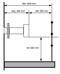
Monitor placement Both the transmitter and receiver units should be easily accessible. A person should be able to stand in front of either the transmitter unit or the receiver unit and adjust the M16 fixing bolts using two standard spanners. For the receiver unit there should be at least 1 m free space measured from the flange fixed to the stack and outwards as shown in Figure 2-1.
power is disconnected or switched off before connecting any cable. Please note that the power plug is the disconnecting device (no separate mains switch on instrument) and should be placed easily accessible for the operator. To install the instrument on the process follow the steps below.
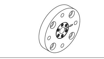
Install transmitter alignment and purging unit (5) onto the stack flange with 4 pcs. M16x60 bolts (ref. Figure 3-4). All 4 bolts on either side must be tightened firmly to compress the large O-ring. Adjust the 4 locking screws prior to mounting the unit, to assure good alignment of the unit and a uniform compression of the O-ring. 2. Install pressurized instrument purging as described in Section
1.2. 3. Open the purging. Refer to Section 3.1.2 for details. 4
. Put the window adapter ring (4) on the alignment unit. Make sure that the O-ring on the alignment unit is tight and greased. The guiding pin on the alignment unit must fit the hole in the adapter ring.
. Affix an O-ring (not greased) to the adapter ring and connect the transmitter unit to the alignment unit. The guiding pin on the adapter ring must fit the hole in the transmitter window. Tighten the transmitter-mounting nut.
. Repeat steps 1-5 for the receiver unit.
. Connect the transmitter and receiver units with the corresponding cable (refer to Figure 6-1 for location of receiver connection on transmitter unit). All connectors are coded with small red pins on the inside.
. Connect external 4–20 mA temperature and pressure probes (ref. Section 6.3 and 6.5). This is optional as some instruments operate without probes. Input signals are connected to the terminals in the power supply unit or directly to the terminals in the main power connector at the transmitter unit. If connected to the power connector the factory-mounted wires should be removed from the terminals in question.
. Connect the transmitter and power supply units with the corresponding cable. The analyzer can now be switched on. This procedure is described in Section 3.2.
Air purging of flanges The instrument windows are kept clean by setting up a positive flow of air through the flanges and into the stack. This purging will prevent particles from settling on the optical windows and contaminating them. The purge gas must be dried and cleaned. We recommend using instrument air for purging. If instrument air is not available a separate blower is needed. A purge flow of approximately 20–50 l/min (process dependent) is sufficient for most installations. Alternatively, the initial velocity of the purge flow in the flanges is set to 1/10 of the gas velocity in the duct. After completion of the installation the purge flow is optimized as described in Section 5.3. The air quality should conform to standard set by ISO 8573.1, Class 2-3. This means particles down to 1 micron should be removed, including coalesced liquid water and oil, and a maximum allowed remaining oil aerosol content of 0.5 mg/m3 at 21C (instrument air). Note that some instruments require nitrogen purging, e.g. O2 instruments for high temperature or pressure applications, some H2O instruments etc.
Purging of transmitter and receiver units For applications where purging of transmitter and receiver units is required the direction of flow is illustrated in Figure 3-3. Since there are optical surfaces inside these units, the cleanness of the gas should be ensured and additional filtering may be necessary. Note that so called “instrument air” may contain some oil and water. If receiver and transmitter are purged with such air they can be permanently damaged after a short time. It is highly recommended to use nitrogen as a purge gas. The purge flow must not be high to avoid pressure build-up inside the units. We recommend reducing the flow to less than 0.5 l/min. If the flow is blocked the units can hold the gas to better than 99.5% during one hour
Isolation flanges For toxic gas and highly corrosive applications especially in combination with high pressure the first flange has to be an isolation flange which isolates the process from the analyzer. In these cases a shut-off valve is always necessary in order to do maintenance on the flange. The isolation flange has to be “custom tailored” for the individual process. The isolation flange may be purged if necessary as described in Section 3.1.2. Due to the additional windows a certain loss of transmission is to be expected. The analyzer will be mounted on the isolation flang
Before dismounting the isolation flange make sure the process is either turned off and safe or the volume between the nearly closed shut-off valve and the flange is purged thoroughly to make sure no harmful gas may leak out.
Leave the instrument switched ON, and disconnect both the transmitter and receiver units from their alignment units by loosening the corresponding mounting nuts. The laser beam from the transmitter is not visible. Avoid looking directly into the transmitter!
2. Remove the adapter ring (no. 4 in Figure 3-1) from the transmitter alignment & purging unit.
3. Mount the red laser alignment jig on the transmitter side using the supplied mounting nut and locate the laser beam on the receiver side using the target. Loosen the adjustment screws shown in Figure 3-4 on the transmitter unit purging flange and move it carefully from side to side and up and down to locate the laser beam in the receiver hole. (You may need two persons.)
4. Having found the laser beam, move the beam to the center of the hole by carefully adjusting the adjustment screws on the transmitter side. Lock the alignment by tightening the locking screws on the transmitter side and check that the alignment has not changed.
5. The laser beam is now centered, but not necessarily parallel with the optical axis of the receiver unit. The following section describes the procedure for aligning the receiver unit to maximize the signal of the analyzer. 3.3.2 Alignment of receiver unit
1. Remove the adapter ring (no.4 in Figure 3-1) from the receiver alignment & purging unit.
2. Disconnect the red laser alignment jig from the transmitter side and mount it on the receiver side. Locate the laser beam on the transmitter side. Loosen the adjustment screws shown in Figure 3-4 on the receiver unit purging flange and move it carefully from side to side and up and down to locate the laser beam in the transmitter hole. (You may need two persons.)
3. Having found the laser beam, move the beam to the center of the hole by carefully adjusting the adjustment screws on the receiver side. Lock the alignment by tightening the locking screws on the receiver side and check that the alignment has not changed. Having completed the previously described operations successfully, the transmitter and receiver should be re-mounted. Check the transmission reading on the transmitter unit LCD. Proceed to Section 3.4, where tuning for maximum transmission using a voltmeter is described.
Tuning for maximum transmission Fine alignment of the transmitter and receiver unit to ensure maximum signal is accomplished by measuring the alignment voltage with a voltmeter and the supplied cable with miniature power plug. The alignment voltage varies from 0V at 0% transmission to −3V (typically) at 100% transmission. The alignment voltage is measured by connecting a voltmeter to the alignment jack on the transmitter unit. This jack is located on Phoenix connector of the transmitter-to-receiver cable as shown in Figure 3-6. A similar alignment jack is found on the receiver unit
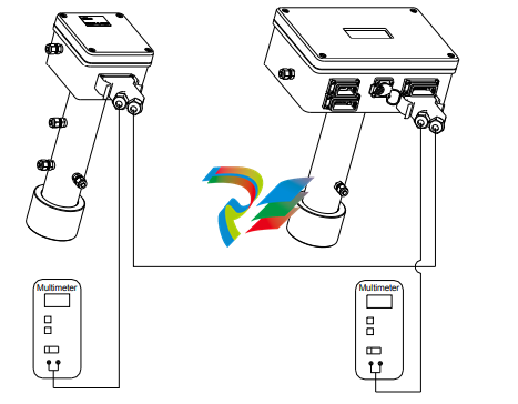
The fine-tuning procedure is as follows:
Connect a voltmeter with floating inputs (battery powered) and measure the alignment voltage from the receiver unit.
2. Maximize the voltmeter reading by carefully adjusting the adjustment screws on the receiver side.
3. Connect a voltmeter with floating inputs (battery powered) and measure the alignment voltage from the transmitter unit.
4. Maximize the voltmeter reading by carefully adjusting the adjustment screws on the transmitter side.
5. Repeat steps 1-2 and 3-4 until no further improvements in voltmeter readings.
6. Tighten the locking screws and check that the alignment has not changed.
7. Disconnect the voltmeter Having completed the previously described operations successfully, the installation and process parameters need to be set correctly using a PC and the analyzer software to enable correct measurements. Setting of these parameters is explained in Section 4
-
 OMRON 3G3XV-A2007 3G3XV-A2007-NEV2
 -
 Omron NJ1019000 NJ1 programable logic controller
 -
 OMRON C120-LK202-EV1/C120LK202EV1
 -
 OMRON C200H-AD003 PLC
 -
 OMRON C200H-CPU23-E COIL 24VDC PLC
 -
 Omron C200HG - C200H-ID212- C200H-OC226 C200HW-BC101 PLC Base Unit
 -
 OMRON C200H-OC222(Output Unit),C200H-PS211(Power Supply Unit),SP001 Module Rack
 -
 OMRON C200H-RT201 PROGRAMMABLE CONTROLLER
 -
 OMRON C200HS-CPU01-E SYSMAC PROGRAMMABLE CONTROLLER
 -
 OMRON C200H-SNT31 C200H Programmable Controllers
 -
 OMRON C200HW-MC402-E Motion control unit
 -
 OMRON C200PC-ISA02-DRM-E PLC ISA bus compatible board card
 -
 OMRON C500-CT012 PLC
 -
 OMRON C500-NC103-E PLC
 -
 OMRON C500-NC222-E PLC
 -
 OMRON C500-PRW05-V1 PLC
 -
 OMRON C500-PRW06 PROGRAMMABLE CONTROLLER
 -
 OMRON C500-PS223-E 3G2A5-PS223-E PLC SYSMAC PROGRAMMABLE CONTROLLER
 -
 OMRON C500-TU001 3G2A5-TU001 PLC PLC
 -
 OMRON C60H-C1DR-DE-V1 Programmable Controllers
 -
 OMRON C60H-C5DR-DE-V1 Programmable Controllers
 -
 OMRON C60H-C6DR-DE-V1 Programmable Controllers
 -
 OMRON CJ1G-CPU44H CPU module
 -
 OMRON CJ1G-CPU45H PLC
 -
 OMRON CJ1M-CPU13-ETN V4.0 PLC PLC
 -
 OMRON CJ1W-AD041-V1 Analog input uni
 -
 OMRON CJ1W-CORT21 PLC module
 -
 OMRON CJ1W-IDP01 Input unit
 -
 OMRON CJ1W-MCH71 - MECHATROLINK-II
 -
 OMRON CJ1W-MD261 Digital I/O
 -
 OMRON CJ1W-NC413 Position control unit
 -
 OMRON CJ1W-NCF71 Position Control Units
 -
 OMRON CJ1W-PTS51 Process Simulation I/O Module
 -
 OMRON CJ1W-PTS52 Process Simulation I/O Module
 -
 OMRON CJ1W-SCU21-V1 PLC
 -
 Omron CJ1W-SCU22 Serial Communication Unit
 -
 OMRON CJ1W-TC001 CJ Series Temperature Control Unit
 -
 Omron CK3W-AX1515N Motion Controller
 -
 Omron CP1E-N60DR-D Compact PLC CPU
 -
 OMRON CP1E-NA20DT1-D PLC PLC
 -
 OMRON CP1H-X40DT-D plc PLC
 -
 OMRON CPM2C-S110C-DRT Interface module
 -
 OMRON CQM1-AD041 PLC
 -
 SAACKE F‑GDSA‑1 / F‑GDSA‑2 Feuerungsautomaten
 -
 SAACKE F-GDSA 143303 Controller SHIPS UPS
 -
 ICS Triplex T8270 Trusted 24 Vdc FanAssembly
 -
 SCHNEIDER M522220000 SA SM_DO16R 16 DIGITAL OUTPUTS MODULE
 -
 LENZ EPL10200-W EPZ-10203 CANPT010W3E
 -
 OMRON CQM1H-ADB21 PLC
 -
OMRON CQM1H-CPU61 PLC
-
 OMRON CQM1H-MAB42 PLC
 -
 OMRON CQM1-TC102 CQM1-TC101 PLC
 -
 OMRON CS1G-CPU44-EV1 PLC
 -
 OMRON CS1G-CPU44H CPU
 -
OMRON CS1H-CPU63-EV1 PLC
-
 OMRON CS1H-CPU66-V1 PLC
 -
 OMRON CS1W-CLK13 PLC communication module
 -
OMRON CS1W-EIP21 PLC
-
 OMRON CS1W-MAD44 PLC PLC
 -
 OMRON CS1W-SCU31-V1 CVM1-BC103 PLC
 -
 Omron CVM1-CPU21-V2 CPU Unit
 -
 OMRON F150-C10E-2 Vision Controller
 -
 OMRON F150-C15E-3 Vision Controller
 -
 OMRON F160-C15E VISION MATE CONTROLLER
 -
 OMRON F500-C10-ETN F500-C15-ETN Vision Sensor
 -
 OMRON F500-VS F500-S1
 -
 OMRON FH-3050 FH Vision Controller
 -
 Omron FQ2-S25050F PLC Smart Camera
 -
 Omron FQM1-MMA22 Motion Module
 -
 OMRON GRT1-TS2P Temperature Module
 -
 OMRON H8PR-24 Cam Positioner
 -
 OMRON IDSC-C1DR-A-E Controller
 -
 OMRON K3HB-HTA-DRT1 Temperature Panel Meter
 -
 Omron KM-N1-FLK Power Detector
 -
 OMRON CJ1G-CPU43H CPU
 -
 OMRON NA5-7W001S-V1 NA5-9W001B-V1 NA5-12W101B-V1 Graphic panel
 -
 OMRON NA5-9W001B-V1 Graphic panel
 -
 OMRON NB10W-TW01B INTERACTIVE DISPLAY
 -
 OMRON NB7W-TW01B +CP1L-EL20DR-D Complete Power Panel
 -
 OMRON NB7W-TX01B INTERACTIVE DISPLAY PLC
 -
 Omron NE1A-SCPU02 Network Controller
 -
 OMRON NA5-7W001B-V1 NA5-7W001S-V1 NA5-9W001B-V1 NA5-12W101B-V1 touch screen
 -
 Omron NS5-SQ00B-V2 NS5-SQ00-V2 NS5-SQ01-V2 NS5-SQ01B-V2 touch display panel
 -
 Omron NJ301-1100 Programmable Logic Controller
 -
 OMRON NJ501-1300 CUP Unit Programmable Controller
 -
 Omron NS12-TS01B-V2 Interactive Display
 -
 OMRON NSJW-ETN21 ETHERNET HMI
 -
 OMRON NT10S-SF121 PLC
 -
 OMRON NT20S-ST121-EV3 Touch Screen
 -
 Omron NX1P2-1140DT-BA Programmable Controller
 -
 OMRON 3G3MV-P10CDT3-E RS422/485 INVERTER BOARD
 -
 Omron C500-ID219 3G2A5-ID219 System Microprocessor
 -
 Omron PLC B7AM-8B16
 -
 OMRON PLC Module CJ1W-AD081-V1
 -
 OMRON R88D-HS10 PLC
 -
OMRON R88D-HT10 plc
-
 OMRON R88D-KN01H-ML2 Servos G5-series
 -
 OMRON R88M-H10030-B plc
 -
 OMRON R88S-H306G plc PLC
 -
 Omron Relay G9SX-GS226-T15-RT
 -
 Omron S8AS-24006N S8AS Smart Power Supply FNIP
 -
 Omron Safety Input Unit NX-SIH400
 -
 OMRON SYSMAC SCY-P1 Sequential Controller
 -
OMRON SYSMAC SCY-P0 13E Sequential Controller
-
 OMRON NS8-TV00B-V2 NS8-TV00-V2 NS8-TV00B-ECV2 NS8-TV00-ECV2 touch display Panel
 -
 Omron V680-CA5D02-V2 Programmable Controller
 -
 OMRON SGDH-04AE-OY Servo Drive
 -
OMRON SGDH-10DE-OY Servo Drive
-
 OMRON SGDS-02A12A PLC + SGMAS-C2ACA21
 -
 OMRON SGMPH-04AAA61D-OY Servo Motor
 -
 Omron ZFV-CA40 Smart Sensor Amp Unit 24VDC 0.8A
 -
OMRON ZFV-NX1 CFP0260 ZFV-A20 VISION CONTROL PANEL
-
 OMRON ZFX-C15 SMART SENSOR AMP UNIT, Vision Sensor LCD
 -
 OMRON ZFX-C20/25-CD SMART SENSOR AMP UNIT, Vision Sensor LCD
 -
 OMRON-DIGITAL TEMPERATURE CONTROLLER E5AC-CX4A5M-014 r
 -
 ABB PFVL141V-2.0MN is an industrial-grade, rectangular roll force load cell
 -
 ABB PFVL141V-1.6MN is an industrial-grade, rectangular roll force load cell
 -
ABB PFVL141V-1.25MN high-performance, rectangular roll force load cell
-
 ABB PFVL141V-1.0MN high-precision, heavy-duty rectangular load cell
 -
 ABB PFVL141V-0.8MN high-precision, heavy-duty rectangular load cell
 -
 ABB PFVL141V-0.63MN high-precision, heavy-duty rectangular load cell
 -
 GE 151X1202YE08PP08 Panel of the case / Structural component
 -
 GE 151X1212HB01MG02 Integrated LCI Controller (Old Model)
 -
 GE 151X1212GC01PC02 LCI Static Startup Controller
 -
 GE 151X1235FD01PK01 High-speed Digital Input Interface Board
 -
 GE 151X1215DK01PC01 Signal Processing / Amplification Board
 -
 GE 151X1238WP99BK01 6-pulse LCI power conversion module
 -
 GE 151X1225DF01PC03RA - Power Conversion / Drive Regulation Board


