
ABBAdvance Optima Continuous gas analyzers AO2000
Description Application Information from the AO2000 gas analyzer can be transferred to a PC or DCS via the Modbus. Measurement values, status signals and also signals of analog and digital inputs and outputs are thus available for further usage. Using the AO-MDDE server the signals can be integrated into standard software (e.g. Excel, Visual Basic or LabVIEW). For further information, see Chapter 4 “AO-MDDE server and demo programs”, page 3535. AO-MDDE can be downloaded from the DVD-ROM which is delivered together with each gas analyzer. AO-MDDE does not support Modbus over TCP/IP. Basic documents
Modbus Application Protocol Specification V1.1b, December 28, 2006
Modbus over Serial Line Specification and Implementation Guide V1.02, December 20, 2006
Modbus Messaging on TCP/IP Implementation Guide V1.0b, October 24, 2006 These documents are available at http://www.modbus.org/specs.php. Interfaces and connection versions The RS232 and the RS485 interface located on the RS232/RS485 module in AO2000 are supported, where only one can be operated at a time. Connection versions are described in Chapter 3 “Modbus connection”, page 30. As an alternative, the Ethernet 10/100BASE-T interface can be used for data transmission via Modbus TCP/IP protocol (from software version 5.1, see page 7).
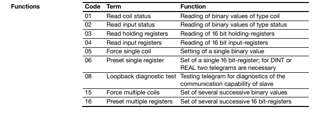
Data transfer For data transfer a combination of frames is used, that consists of 1/0 information, united to one or more telegrams. Frame The transfer values are decomposed in bytes (= 8 bit). Each of these bytes is completed by one start-bit, possibly one parity-bit (even number of “1”) and one stop-bit. In the following description the term “byte” will be used, even if ten or eleven bits will be transferred including the start-, stop- and parity-bits. Telegrams The Modbus telegrams consist of the following frames: address (1 byte), function (1 byte), data (n bytes) and check sum (2 bytes). The telegrams also take on the “shake-hands-function”: each telegram from master to slave must be responded, before a new telegram is allowed to be transmitted. The computer has to have in a adequate supervision, for excluding non answering bus participants (time-out-supervision). Admissible addresses As addresses for the participants of the bus the numbers 1 to 255 are admitted. The address 0 is the global address (broadcast-address). When this address will be used in a telegram, all participants accept this telegram without an acknowledgment to the master.
Integration The AO2000 Modbus/TCP server expects requests from the current IP addresses via the communication port. A maximum of 4 clients can be connected to the Modbus/TCP server of an AO2000 at the same time. If the connection to a client breaks down, the connection status in the Modbus/TCP server is enabled again after a max. 60 seconds. Reading out data from the AO2000 Modbus/TCP server The following procedure must be executed on the Modbus client, in order to receive data from the AO2000 Modbus/TCP server: 1. Establish a TCP connection to port 502 on the server. 2. Create a Modbus request. 3. Send the Modbus request incl. the Modbus/TCP MBAP Header. 4. Wait for a response to the same TCP connection. 5. Read the first 6 bytes of the response; these state the length of the response. 6. Read the remaining bytes of the response. Functions, addresses and registers The supported functions and the addresses and registers of Modbus over TCP/IP are equivalent to those of Modbus over RS232/RS485
Function code Function code 43 with MEI 14 (MEI = Modbus Encapsulated Interface) is used to read the device parameters to read measured values, transfer simulation data, apply reference material. Address assignment of the device parameters for the function code 43 There is read access to the device parameters. Measurement components are mapped with the following structure: Name Measurement range start Measurement range end Unit The number of the first measured values register is listed under BasisM in the device parameters list. The measured value status is implemented as NAMUR status: Bit Assignmant 0 Error 1 Maintenance 2 Maintenance request 3 Beyond specification 4 Test operation, simulation measured value transmitted 5…15 Reserved for extensions 16…31 Vendor-specific The number of the first simulation data register is listed under BasisS in the device parameters list. The number of the register to apply reference material is listed under BasisR in the device parameters list. Maximum 32 Bus DIs are reserved for transferring reference material. The register "status of application" is used for feedback of the DIs for which a hardware digital output is connected. When reference material is applied, the status "maintenance" is set and a message is displayed on the gas analyzer's screen
Principle The AO2000 series gas analyzers are modular and very flexible. A gas analyzer can consist of one or more analyzer modules which in itself can measure one or more components. It is also possible to connect different kinds of I/O-modules and I/O-boards to a device. For this reason the Modbus addressing schema is not static. Data format There are six flexible groups, four configurable groups and two fixed length groups of information defined in a AO2000 gas analyzer. The grouped information can be read through “Single Modbus Request”. Flexible groups The flexible groups are: Measurement values (see page 12) Analog inputs (see page 12) Analog outputs (see page 13) Digital inputs (see page 13) Digital outputs (see page 14) Measurement range feedback (see page 17) Measurement range configuration (see page 18) Measurement range drift values (see page 19) QAL3 calibration data (see page 21) Each flexible group has a fixed start address and, depending on the system layout, a variable number of elements. Configurable groups The configurable groups are: Bus analog inputs (see page 14) Bus analog outputs (see page 15) Bus digital inputs (see page 15) Bus digital outputs (see page 15) Each configurable group has a fixed start address and, depending on the user configuration, a variable number of elements. Fixed length groups The fixed length groups are: Configuration display (see page 16) Status (see page 16)
-
 OMRON 3G3XV-A2007 3G3XV-A2007-NEV2
 -
 Omron NJ1019000 NJ1 programable logic controller
 -
 OMRON C120-LK202-EV1/C120LK202EV1
 -
 OMRON C200H-AD003 PLC
 -
 OMRON C200H-CPU23-E COIL 24VDC PLC
 -
 Omron C200HG - C200H-ID212- C200H-OC226 C200HW-BC101 PLC Base Unit
 -
 OMRON C200H-OC222(Output Unit),C200H-PS211(Power Supply Unit),SP001 Module Rack
 -
 OMRON C200H-RT201 PROGRAMMABLE CONTROLLER
 -
 OMRON C200HS-CPU01-E SYSMAC PROGRAMMABLE CONTROLLER
 -
 OMRON C200H-SNT31 C200H Programmable Controllers
 -
 OMRON C200HW-MC402-E Motion control unit
 -
 OMRON C200PC-ISA02-DRM-E PLC ISA bus compatible board card
 -
 OMRON C500-CT012 PLC
 -
 OMRON C500-NC103-E PLC
 -
 OMRON C500-NC222-E PLC
 -
 OMRON C500-PRW05-V1 PLC
 -
 OMRON C500-PRW06 PROGRAMMABLE CONTROLLER
 -
 OMRON C500-PS223-E 3G2A5-PS223-E PLC SYSMAC PROGRAMMABLE CONTROLLER
 -
 OMRON C500-TU001 3G2A5-TU001 PLC PLC
 -
 OMRON C60H-C1DR-DE-V1 Programmable Controllers
 -
 OMRON C60H-C5DR-DE-V1 Programmable Controllers
 -
 OMRON C60H-C6DR-DE-V1 Programmable Controllers
 -
 OMRON CJ1G-CPU44H CPU module
 -
 OMRON CJ1G-CPU45H PLC
 -
 OMRON CJ1M-CPU13-ETN V4.0 PLC PLC
 -
 OMRON CJ1W-AD041-V1 Analog input uni
 -
 OMRON CJ1W-CORT21 PLC module
 -
 OMRON CJ1W-IDP01 Input unit
 -
 OMRON CJ1W-MCH71 - MECHATROLINK-II
 -
 OMRON CJ1W-MD261 Digital I/O
 -
 OMRON CJ1W-NC413 Position control unit
 -
 OMRON CJ1W-NCF71 Position Control Units
 -
 OMRON CJ1W-PTS51 Process Simulation I/O Module
 -
 OMRON CJ1W-PTS52 Process Simulation I/O Module
 -
 OMRON CJ1W-SCU21-V1 PLC
 -
 Omron CJ1W-SCU22 Serial Communication Unit
 -
 OMRON CJ1W-TC001 CJ Series Temperature Control Unit
 -
 Omron CK3W-AX1515N Motion Controller
 -
 Omron CP1E-N60DR-D Compact PLC CPU
 -
 OMRON CP1E-NA20DT1-D PLC PLC
 -
 OMRON CP1H-X40DT-D plc PLC
 -
 OMRON CPM2C-S110C-DRT Interface module
 -
 OMRON CQM1-AD041 PLC
 -
 SAACKE F‑GDSA‑1 / F‑GDSA‑2 Feuerungsautomaten
 -
 SAACKE F-GDSA 143303 Controller SHIPS UPS
 -
 ICS Triplex T8270 Trusted 24 Vdc FanAssembly
 -
 SCHNEIDER M522220000 SA SM_DO16R 16 DIGITAL OUTPUTS MODULE
 -
 LENZ EPL10200-W EPZ-10203 CANPT010W3E
 -
 OMRON CQM1H-ADB21 PLC
 -
OMRON CQM1H-CPU61 PLC
-
 OMRON CQM1H-MAB42 PLC
 -
 OMRON CQM1-TC102 CQM1-TC101 PLC
 -
 OMRON CS1G-CPU44-EV1 PLC
 -
 OMRON CS1G-CPU44H CPU
 -
OMRON CS1H-CPU63-EV1 PLC
-
 OMRON CS1H-CPU66-V1 PLC
 -
 OMRON CS1W-CLK13 PLC communication module
 -
OMRON CS1W-EIP21 PLC
-
 OMRON CS1W-MAD44 PLC PLC
 -
 OMRON CS1W-SCU31-V1 CVM1-BC103 PLC
 -
 Omron CVM1-CPU21-V2 CPU Unit
 -
 OMRON F150-C10E-2 Vision Controller
 -
 OMRON F150-C15E-3 Vision Controller
 -
 OMRON F160-C15E VISION MATE CONTROLLER
 -
 OMRON F500-C10-ETN F500-C15-ETN Vision Sensor
 -
 OMRON F500-VS F500-S1
 -
 OMRON FH-3050 FH Vision Controller
 -
 Omron FQ2-S25050F PLC Smart Camera
 -
 Omron FQM1-MMA22 Motion Module
 -
 OMRON GRT1-TS2P Temperature Module
 -
 OMRON H8PR-24 Cam Positioner
 -
 OMRON IDSC-C1DR-A-E Controller
 -
 OMRON K3HB-HTA-DRT1 Temperature Panel Meter
 -
 Omron KM-N1-FLK Power Detector
 -
 OMRON CJ1G-CPU43H CPU
 -
 OMRON NA5-7W001S-V1 NA5-9W001B-V1 NA5-12W101B-V1 Graphic panel
 -
 OMRON NA5-9W001B-V1 Graphic panel
 -
 OMRON NB10W-TW01B INTERACTIVE DISPLAY
 -
 OMRON NB7W-TW01B +CP1L-EL20DR-D Complete Power Panel
 -
 OMRON NB7W-TX01B INTERACTIVE DISPLAY PLC
 -
 Omron NE1A-SCPU02 Network Controller
 -
 OMRON NA5-7W001B-V1 NA5-7W001S-V1 NA5-9W001B-V1 NA5-12W101B-V1 touch screen
 -
 Omron NS5-SQ00B-V2 NS5-SQ00-V2 NS5-SQ01-V2 NS5-SQ01B-V2 touch display panel
 -
 Omron NJ301-1100 Programmable Logic Controller
 -
 OMRON NJ501-1300 CUP Unit Programmable Controller
 -
 Omron NS12-TS01B-V2 Interactive Display
 -
 OMRON NSJW-ETN21 ETHERNET HMI
 -
 OMRON NT10S-SF121 PLC
 -
 OMRON NT20S-ST121-EV3 Touch Screen
 -
 Omron NX1P2-1140DT-BA Programmable Controller
 -
 OMRON 3G3MV-P10CDT3-E RS422/485 INVERTER BOARD
 -
 Omron C500-ID219 3G2A5-ID219 System Microprocessor
 -
 Omron PLC B7AM-8B16
 -
 OMRON PLC Module CJ1W-AD081-V1
 -
 OMRON R88D-HS10 PLC
 -
OMRON R88D-HT10 plc
-
 OMRON R88D-KN01H-ML2 Servos G5-series
 -
 OMRON R88M-H10030-B plc
 -
 OMRON R88S-H306G plc PLC
 -
 Omron Relay G9SX-GS226-T15-RT
 -
 Omron S8AS-24006N S8AS Smart Power Supply FNIP
 -
 Omron Safety Input Unit NX-SIH400
 -
 OMRON SYSMAC SCY-P1 Sequential Controller
 -
OMRON SYSMAC SCY-P0 13E Sequential Controller
-
 OMRON NS8-TV00B-V2 NS8-TV00-V2 NS8-TV00B-ECV2 NS8-TV00-ECV2 touch display Panel
 -
 Omron V680-CA5D02-V2 Programmable Controller
 -
 OMRON SGDH-04AE-OY Servo Drive
 -
OMRON SGDH-10DE-OY Servo Drive
-
 OMRON SGDS-02A12A PLC + SGMAS-C2ACA21
 -
 OMRON SGMPH-04AAA61D-OY Servo Motor
 -
 Omron ZFV-CA40 Smart Sensor Amp Unit 24VDC 0.8A
 -
OMRON ZFV-NX1 CFP0260 ZFV-A20 VISION CONTROL PANEL
-
 OMRON ZFX-C15 SMART SENSOR AMP UNIT, Vision Sensor LCD
 -
 OMRON ZFX-C20/25-CD SMART SENSOR AMP UNIT, Vision Sensor LCD
 -
 OMRON-DIGITAL TEMPERATURE CONTROLLER E5AC-CX4A5M-014 r
 -
 ABB PFVL141V-2.0MN is an industrial-grade, rectangular roll force load cell
 -
 ABB PFVL141V-1.6MN is an industrial-grade, rectangular roll force load cell
 -
ABB PFVL141V-1.25MN high-performance, rectangular roll force load cell
-
 ABB PFVL141V-1.0MN high-precision, heavy-duty rectangular load cell
 -
 ABB PFVL141V-0.8MN high-precision, heavy-duty rectangular load cell
 -
 ABB PFVL141V-0.63MN high-precision, heavy-duty rectangular load cell
 -
 GE 151X1202YE08PP08 Panel of the case / Structural component
 -
 GE 151X1212HB01MG02 Integrated LCI Controller (Old Model)
 -
 GE 151X1212GC01PC02 LCI Static Startup Controller
 -
 GE 151X1235FD01PK01 High-speed Digital Input Interface Board
 -
 GE 151X1215DK01PC01 Signal Processing / Amplification Board
 -
 GE 151X1238WP99BK01 6-pulse LCI power conversion module
 -
 GE 151X1225DF01PC03RA - Power Conversion / Drive Regulation Board


