
ABBCrane motion controller 25-2000 A, 380-690 V
News in 10_054 and 10_055 10_054 Hardware 1) New thyristor module DASD 145, 600 V - 500 A 2) Improved speed control with incremental encoder at very low speed with new firmware PU_APP12 in DAPU 100 board (from May 2007) 3) Start of replacement of semiconductor fuses from higher voltage to 690 V with higher current rating in DASD 146, 147, 156, 157 based on the technical development. 4) Control sequence for output relays and safety brake lifter contactor for DARA 200 supervision system. Software functions 5) Display of DAPC 100 shows "54" when there is no Fault. "54 indicates 10_05, revision 4. 6) A large number of parameters fixed to constants for quicker parameterisation. 7) Acceleration control of travel motions as alternative to speed control developed and included. 8) Torque control with DARA 1001 is removed as acceleration control is better. SW release 10_053 shall be asked for when ordering spare part board DAPC 100. 9) Positioning "Soft limit switch" is removed as positioning on incremental encoder no more is recommended due to the development of absolute encoders. SW release 10_053 shall be asked for when ordering spare part board DAPC 100. 10) Firing angle can be modified in regenerative mode. Extremely loaded motors with high CosFi that else can operate in two-phase mode with heavy mechanical vibrations. 11) Correction of execution time to prevent a 10 ms long brake opening when trying to lift a load with load above the mechanical overload level. 12) Supervision time of MF-link and Remote I/O-link set to 500 ms time. 13) Fast stop function included; an active or passive signal can force the motion controller to sop also in healthy mode with master switch in driving position. 14) Speed dependent gain improved by separate break points for stand still (0% reference) in addition to existing 10%, 25%, 50% and 100% speed reference. 15) A step reference can be optimised for light motions (travel or hoist) by setting 08.01 to 5. With value 5 overshooting is prevented as the integral part of the speed regulator is set to zero each time the ramp output value coincides with the step reference. By setting 08.01 to 6 the integral part is not reset, which minimises load droop for hoists and is more suitable for fine positioning of heavy travel motions. 16) Standard value for switch to super synchronous speed changed from 85% to 95% speed. 17) Better function to enter in open control with light load. Full motor voltage is no longer required. 18) Contactor K3 will always close in super synchronous mode, if installed. 19) Function "Adoption to low line voltage with longer ramp times" is fixed, and cannot be deselected. 20) DO 6 can be used off-delayed to control, as example, lubrication pumps or rail cleaning blowers. 21) DI 15 can be used to switch between parameter sets 1 and 2 in installations without any remote I/0. 10_055 Software functions 22) Display of DAPC 100 shows "55" when there is no Fault. "55 indicates 10_05, revision 5. 23) Bypass functions as rescue operation with one of two (large) motors, and for E-room/cubicle loss reduction 24) Faults for operation are as before reset by cran

Historical release information: From 10_053 to 10_053C 10_053 Hardware 25) Increased voltage range to 1000 V rated rotor voltage for EH rotor contactors. Software functions 26) Display of DAPC 100 shows "53" when there is no Fault. "53 indicates 10_05, revision 3. 27) User does not have to contact ABB to modify a hidden parameter from its standard value to use MasterFollower. If that was not done, the Followers brake was directly released when Masters Direction signals (A or B) was removed. 28) Correction of logic for dynamic Master-Follower partner selection. Master-Follower partner is now fully selectable by macro-change. 29) Correction of very occasional trips in 60 Hz networks due to collision between current regulator execution and communication links. 30) Rotor contactors do not open during acceleration in case reverse thyristor bridge is commended by speed regulator. 31) Rotor contactors K2 and K3 do not close during acceleration if the stator current is larger than parameter 12.10 for hoists and 12.11 for Travel motions. The system is less sensitive for line voltage dips and low class power system design. The standard values should only be modified for macros used for temporary overload. 32) Standard values of parameter for rotor contactor closing time modified: 12.29 from 80 ms to 60 ms 33) Standard values of parameters related to thyristor bridge reversal have been modified; these are not modified by most users: 11.44 from 30 ms to 20 ms 11.46 from 200 ms to 50 ms 34) Standard value of parameter 08.18 changed from 0 to 1. Standard is 1 meaning active function for line voltage adopted ramp times. Tool program 35) For Monitor and View recording, the gridlines can be turned on and off. 36) For Monitor and View recording, two lines for each of six signals can be displayed. 37) For View recording, a vertical time-line can be moved in the chart, and the signal values at this time are presented. 38) Possible to add comments to record files, ∗.asg. 10_053A, ex works from 2006-08-01 Software functions 39) The additional brake setting based on speed reference has been corrected. The normal brake setting has worked and works without any remark. 40) The associated timer function for brake setting based on speed reference, parameter 06.08, has incorrectly been implemented as an ON-delay of reference coming to zero instead as an OFF-delay. Well working installations should not be modified. 41) A Follower in a MF-configuration is changed to use the uncorrected Masters speed reference for brake set-ting instead of the Followers lively speed reference. The action is more predictable. Well working installations should not be modified. 42) The slow down and stop limit switches in Master-Follower are corrected according to the existing specification to a true OR-action between the Masters and Followers limit switches. 10_053B, ex works from 2006-09-03 Software functions 43) For Master-Follower such states in Follower that cause fault codes in Follower, but not requires the Master to stop are not causing Master-Follower links faults any more. 44) Master-Follower link supervision corrected. Permitted down time was always zero (un-delayed trip), what-ever parameter value was set. After correction the trip is delayed with value in milliseconds of parameter 30.01. 45) Automatic resynchronization of Electrical Shaft after reactivation of the mode (in practice at first CRANE ON after changing from single drive to Master-Follower) restored after having been removed by mistake in Release 10_03A
1) Technical information and downloads are available on www.abb.com/cranes
2) About 10 new default for parameter values.
3) New sorting of parameters for Design, basic Start up and Special functions.
4) To enter super-synchronous lowering is based only on speed reference and not on estimated speed when rotor frequency based speed feedback is used.
5) A faster control response then exit from super-synchronous lowering to regulated speed range with rotor frequency based speed feedback by injection of predicted plugging current.
6) A faster return then exit from super-synchronous lowering to regulated speed range. The faster return is not dependent on setting of retardation time or type of speed feedback. A driver will have a virtually direct response then notching back
7) A faster return then changing from full speed reference with typically reached 90% final speed for travel motions and hoists up. The faster return is not dependent on setting of retardation time or type of speed feedback. A driver will have a virtually direct response then notching back.
8) The function of previous releases with higher gain for a certain time after controller release has been removed, as the general speed control is capable of giving good properties also in this situation.
9) N+1 run (DRI_TYPE = 4) has been removed as this situation is covered by the four parameter sets.
10) Possibility to connect a Low pass-filter to the speed feedback. With time set with parameter. The standard setting is to not use this filter, but it can improve the control for mechanically unstable cranes.
11) For manually operated cranes a Travel motion can have a virtual plug braking if pulling the master switch to the opposite direction than the actual motion. This function will shorten the deceleration ramp time.
12) The I- and P-gains can be functions of Speed reference range when needed to have very fast control as for sway control or automated cranes in general. There are 4 + 4 = 8 new speed regulator parameters for this.
13) The rotor contactors will not close if the line current is too low. The control will be performed with averagely lower current and better controllability of the motor
14) The ASTAT controller can be forced to operate with rotor contactor K1 closed in hoisting direction to better adopt to older existing rotor resistors
15) The rotor contactors K2 and K3 will not close in lowering operation except for super-synchronous lowering.
16) A detection of wrong connection of direction signals and polarity of speed reference. Gives Fault code 50.
17) Electrical shaft: The phenomena that the Follower stops earlier than Master (only noted in some applications with slow retardation ramp) is removed.
18) Electrical shaft: The Follower will never move in the opposite direction to the master switch, it will stay at zero speed until the Master has equalised the position error.
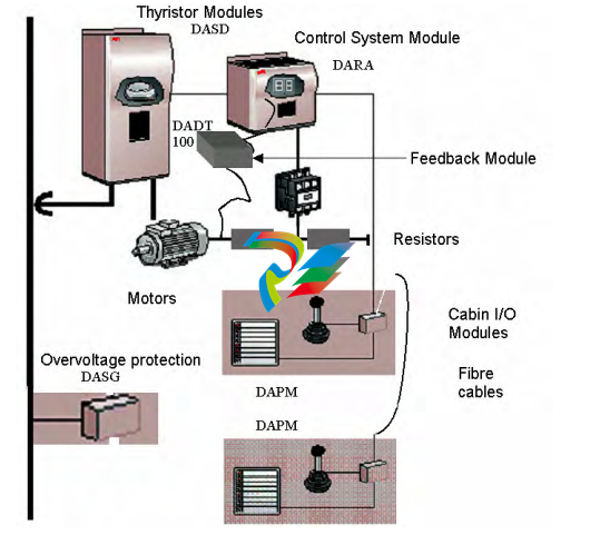
19) Speed feedback with rotor frequency can be selected from any of the maximally four motors, not only from motor number 1. This is important for shared motion and redundant drive installations. 20) Annunciation with LED no. 8 in "Cabin I/O" changed to: Flashing green: The control system is working and is powered but with detected fault. Steady green: Powered, no Fault. No light: Control system is out. 21) Status display of Control System Module visible with the cover mounted through a window in the cover (from September 2002). Tool program 22) Print out of Parameters will include "Normal Values". It is indicated by a star "∗" then any of the four values are different from Normal 23) Parameter printout with All parameters or only Design/Start up/Special 24) The logical signals in the Monitor Tool have thinner lines than in previous version. 25) Setting of offset of value signals in the Monitor Tool can be done. 26) Predefinition of sets with six signals with colours and scaling in the Monitor Tool 27) Default settings for comm.-port and speed 28) Tool program able to communicate over TCP/IP (not in freeware version)
1) Technical information and downloads are available on www.abb.com/cranes 2) About 10 new default for parameter values. 3) New sorting of parameters for Design, basic Start up and Special functions. 4) To enter super-synchronous lowering is based only on speed reference and not on estimated speed when rotor frequency based speed feedback is used. 5) A faster control response then exit from super-synchronous lowering to regulated speed range with rotor frequency based speed feedback by injection of predicted plugging current. 6) A faster return then exit from super-synchronous lowering to regulated speed range. The faster return is not dependent on setting of retardation time or type of speed feedback. A driver will have a virtually direct response then notching back 7) A faster return then changing from full speed reference with typically reached 90% final speed for travel motions and hoists up. The faster return is not dependent on setting of retardation time or type of speed feedback. A driver will have a virtually direct response then notching back. 8) The function of previous releases with higher gain for a certain time after controller release has been removed, as the general speed control is capable of giving good properties also in this situation. 9) N+1 run (DRI_TYPE = 4) has been removed as this situation is covered by the four parameter sets. 10) Possibility to connect a Low pass-filter to the speed feedback. With time set with parameter. The standard setting is to not use this filter, but it can improve the control for mechanically unstable cranes. 11) For manually operated cranes a Travel motion can have a virtual plug braking if pulling the master switch to the opposite direction than the actual motion. This function will shorten the deceleration ramp time. 12) The I- and P-gains can be functions of Speed reference range when needed to have very fast control as for sway control or automated cranes in general. There are 4 + 4 = 8 new speed regulator parameters for this. 13) The rotor contactors will not close if the line current is too low. The control will be performed with averagely lower current and better controllability of the motor 14) The ASTAT controller can be forced to operate with rotor contactor K1 closed in hoisting direction to better adopt to older existing rotor resistors 15) The rotor contactors K2 and K3 will not close in lowering operation except for super-synchronous lowering. 16) A detection of wrong connection of direction signals and polarity of speed reference. Gives Fault code 50. 17) Electrical shaft: The phenomena that the Follower stops earlier than Master (only noted in some applications with slow retardation ramp) is removed. 18) Electrical shaft: The Follower will never move in the opposite direction to the master switch, it will stay at zero speed until the Master has equalised the position error. 19) Speed feedback with rotor frequency can be selected from any of the maximally four motors, not only from motor number 1. This is important for shared motion and redundant drive installations. 20) Annunciation with LED no. 8 in "Cabin I/O" changed to: Flashing green: The control system is working and is powered but with detected fault. Steady green: Powered, no Fault. No light: Control system is out. 21) Status display of Control System Module visible with the cover mounted through a window in the cover (from September 2002). Tool program 22) Print out of Parameters will include "Normal Values". It is indicated by a star "∗" then any of the four values are different from Normal 23) Parameter printout with All parameters or only Design/Start up/Special 24) The logical signals in the Monitor Tool have thinner lines than in previous version. 25) Setting of offset of value signals in the Monitor Tool can be done. 26) Predefinition of sets with six signals with colours and scaling in the Monitor Tool 27) Default settings for comm.-port and speed 28) Tool program able to communicate over TCP/IP (not in freeware version)
-
 OMRON 3G3XV-A2007 3G3XV-A2007-NEV2
 -
 Omron NJ1019000 NJ1 programable logic controller
 -
 OMRON C120-LK202-EV1/C120LK202EV1
 -
 OMRON C200H-AD003 PLC
 -
 OMRON C200H-CPU23-E COIL 24VDC PLC
 -
 Omron C200HG - C200H-ID212- C200H-OC226 C200HW-BC101 PLC Base Unit
 -
 OMRON C200H-OC222(Output Unit),C200H-PS211(Power Supply Unit),SP001 Module Rack
 -
 OMRON C200H-RT201 PROGRAMMABLE CONTROLLER
 -
 OMRON C200HS-CPU01-E SYSMAC PROGRAMMABLE CONTROLLER
 -
 OMRON C200H-SNT31 C200H Programmable Controllers
 -
 OMRON C200HW-MC402-E Motion control unit
 -
 OMRON C200PC-ISA02-DRM-E PLC ISA bus compatible board card
 -
 OMRON C500-CT012 PLC
 -
 OMRON C500-NC103-E PLC
 -
 OMRON C500-NC222-E PLC
 -
 OMRON C500-PRW05-V1 PLC
 -
 OMRON C500-PRW06 PROGRAMMABLE CONTROLLER
 -
 OMRON C500-PS223-E 3G2A5-PS223-E PLC SYSMAC PROGRAMMABLE CONTROLLER
 -
 OMRON C500-TU001 3G2A5-TU001 PLC PLC
 -
 OMRON C60H-C1DR-DE-V1 Programmable Controllers
 -
 OMRON C60H-C5DR-DE-V1 Programmable Controllers
 -
 OMRON C60H-C6DR-DE-V1 Programmable Controllers
 -
 OMRON CJ1G-CPU44H CPU module
 -
 OMRON CJ1G-CPU45H PLC
 -
 OMRON CJ1M-CPU13-ETN V4.0 PLC PLC
 -
 OMRON CJ1W-AD041-V1 Analog input uni
 -
 OMRON CJ1W-CORT21 PLC module
 -
 OMRON CJ1W-IDP01 Input unit
 -
 OMRON CJ1W-MCH71 - MECHATROLINK-II
 -
 OMRON CJ1W-MD261 Digital I/O
 -
 OMRON CJ1W-NC413 Position control unit
 -
 OMRON CJ1W-NCF71 Position Control Units
 -
 OMRON CJ1W-PTS51 Process Simulation I/O Module
 -
 OMRON CJ1W-PTS52 Process Simulation I/O Module
 -
 OMRON CJ1W-SCU21-V1 PLC
 -
 Omron CJ1W-SCU22 Serial Communication Unit
 -
 OMRON CJ1W-TC001 CJ Series Temperature Control Unit
 -
 Omron CK3W-AX1515N Motion Controller
 -
 Omron CP1E-N60DR-D Compact PLC CPU
 -
 OMRON CP1E-NA20DT1-D PLC PLC
 -
 OMRON CP1H-X40DT-D plc PLC
 -
 OMRON CPM2C-S110C-DRT Interface module
 -
 OMRON CQM1-AD041 PLC
 -
 SAACKE F‑GDSA‑1 / F‑GDSA‑2 Feuerungsautomaten
 -
 SAACKE F-GDSA 143303 Controller SHIPS UPS
 -
 ICS Triplex T8270 Trusted 24 Vdc FanAssembly
 -
 SCHNEIDER M522220000 SA SM_DO16R 16 DIGITAL OUTPUTS MODULE
 -
 LENZ EPL10200-W EPZ-10203 CANPT010W3E
 -
 OMRON CQM1H-ADB21 PLC
 -
OMRON CQM1H-CPU61 PLC
-
 OMRON CQM1H-MAB42 PLC
 -
 OMRON CQM1-TC102 CQM1-TC101 PLC
 -
 OMRON CS1G-CPU44-EV1 PLC
 -
 OMRON CS1G-CPU44H CPU
 -
OMRON CS1H-CPU63-EV1 PLC
-
 OMRON CS1H-CPU66-V1 PLC
 -
 OMRON CS1W-CLK13 PLC communication module
 -
OMRON CS1W-EIP21 PLC
-
 OMRON CS1W-MAD44 PLC PLC
 -
 OMRON CS1W-SCU31-V1 CVM1-BC103 PLC
 -
 Omron CVM1-CPU21-V2 CPU Unit
 -
 OMRON F150-C10E-2 Vision Controller
 -
 OMRON F150-C15E-3 Vision Controller
 -
 OMRON F160-C15E VISION MATE CONTROLLER
 -
 OMRON F500-C10-ETN F500-C15-ETN Vision Sensor
 -
 OMRON F500-VS F500-S1
 -
 OMRON FH-3050 FH Vision Controller
 -
 Omron FQ2-S25050F PLC Smart Camera
 -
 Omron FQM1-MMA22 Motion Module
 -
 OMRON GRT1-TS2P Temperature Module
 -
 OMRON H8PR-24 Cam Positioner
 -
 OMRON IDSC-C1DR-A-E Controller
 -
 OMRON K3HB-HTA-DRT1 Temperature Panel Meter
 -
 Omron KM-N1-FLK Power Detector
 -
 OMRON CJ1G-CPU43H CPU
 -
 OMRON NA5-7W001S-V1 NA5-9W001B-V1 NA5-12W101B-V1 Graphic panel
 -
 OMRON NA5-9W001B-V1 Graphic panel
 -
 OMRON NB10W-TW01B INTERACTIVE DISPLAY
 -
 OMRON NB7W-TW01B +CP1L-EL20DR-D Complete Power Panel
 -
 OMRON NB7W-TX01B INTERACTIVE DISPLAY PLC
 -
 Omron NE1A-SCPU02 Network Controller
 -
 OMRON NA5-7W001B-V1 NA5-7W001S-V1 NA5-9W001B-V1 NA5-12W101B-V1 touch screen
 -
 Omron NS5-SQ00B-V2 NS5-SQ00-V2 NS5-SQ01-V2 NS5-SQ01B-V2 touch display panel
 -
 Omron NJ301-1100 Programmable Logic Controller
 -
 OMRON NJ501-1300 CUP Unit Programmable Controller
 -
 Omron NS12-TS01B-V2 Interactive Display
 -
 OMRON NSJW-ETN21 ETHERNET HMI
 -
 OMRON NT10S-SF121 PLC
 -
 OMRON NT20S-ST121-EV3 Touch Screen
 -
 Omron NX1P2-1140DT-BA Programmable Controller
 -
 OMRON 3G3MV-P10CDT3-E RS422/485 INVERTER BOARD
 -
 Omron C500-ID219 3G2A5-ID219 System Microprocessor
 -
 Omron PLC B7AM-8B16
 -
 OMRON PLC Module CJ1W-AD081-V1
 -
 OMRON R88D-HS10 PLC
 -
OMRON R88D-HT10 plc
-
 OMRON R88D-KN01H-ML2 Servos G5-series
 -
 OMRON R88M-H10030-B plc
 -
 OMRON R88S-H306G plc PLC
 -
 Omron Relay G9SX-GS226-T15-RT
 -
 Omron S8AS-24006N S8AS Smart Power Supply FNIP
 -
 Omron Safety Input Unit NX-SIH400
 -
 OMRON SYSMAC SCY-P1 Sequential Controller
 -
OMRON SYSMAC SCY-P0 13E Sequential Controller
-
 OMRON NS8-TV00B-V2 NS8-TV00-V2 NS8-TV00B-ECV2 NS8-TV00-ECV2 touch display Panel
 -
 Omron V680-CA5D02-V2 Programmable Controller
 -
 OMRON SGDH-04AE-OY Servo Drive
 -
OMRON SGDH-10DE-OY Servo Drive
-
 OMRON SGDS-02A12A PLC + SGMAS-C2ACA21
 -
 OMRON SGMPH-04AAA61D-OY Servo Motor
 -
 Omron ZFV-CA40 Smart Sensor Amp Unit 24VDC 0.8A
 -
OMRON ZFV-NX1 CFP0260 ZFV-A20 VISION CONTROL PANEL
-
 OMRON ZFX-C15 SMART SENSOR AMP UNIT, Vision Sensor LCD
 -
 OMRON ZFX-C20/25-CD SMART SENSOR AMP UNIT, Vision Sensor LCD
 -
 OMRON-DIGITAL TEMPERATURE CONTROLLER E5AC-CX4A5M-014 r
 -
 ABB PFVL141V-2.0MN is an industrial-grade, rectangular roll force load cell
 -
 ABB PFVL141V-1.6MN is an industrial-grade, rectangular roll force load cell
 -
ABB PFVL141V-1.25MN high-performance, rectangular roll force load cell
-
 ABB PFVL141V-1.0MN high-precision, heavy-duty rectangular load cell
 -
 ABB PFVL141V-0.8MN high-precision, heavy-duty rectangular load cell
 -
 ABB PFVL141V-0.63MN high-precision, heavy-duty rectangular load cell
 -
 GE 151X1202YE08PP08 Panel of the case / Structural component
 -
 GE 151X1212HB01MG02 Integrated LCI Controller (Old Model)
 -
 GE 151X1212GC01PC02 LCI Static Startup Controller
 -
 GE 151X1235FD01PK01 High-speed Digital Input Interface Board
 -
 GE 151X1215DK01PC01 Signal Processing / Amplification Board
 -
 GE 151X1238WP99BK01 6-pulse LCI power conversion module
 -
 GE 151X1225DF01PC03RA - Power Conversion / Drive Regulation Board


