
ABBACS5000 water-cooledUser manual
Legal disclaimer
This document contains information about one or more ABB products and may include a description of or a reference to one or more standards that are relevant to the ABB products. The presence of any such description of a standard or reference to a standard is not a representation that all of the ABB products referenced in this document include all the features of the described or referenced standard. In order to determine the specific features included in a particular ABB product, the product specifications for the particular ABB product apply. The buyer acknowledges the proprietary and confidential nature of the information contained in this document and agrees that all rights to and concerning the information contained in this document remain vested in ABB, in particular with regard to any intellectual property rights. Nothing contained herein shall oblige ABB to furnish any particular information to the buyer. The information in this document is subject to change without notice and should not be construed as a binding declaration of ABB. ABB assumes no responsibility for any errors or omissions in this document. Products described or referenced in this document are designed to be connected with networks and provide information and data through network interfaces. The products must be connected to a secure network. It is the sole responsibility of the buyer of the products to provide and continuously ensure a secure connection between the product and the system network and/or any other networks that may be connected to the product. ABB is in no event liable for the security of the network used by buyer. The buyer of the product must establish and maintain appropriate measures, including, but not limited to, the installation of firewalls, application of authentication measures, encryption of data, installation of antivirus programs, and so on, to protect these products, the network, its system, and interfaces against security breaches, unauthorized access, interference, intrusion, leakage, and/or theft of data or information. Any liability of ABB in this regard is excluded. ABB may perform functionality testing on the products and may release updates. However, it is the sole responsibility of the buyer of the product to ensure that any product updates or other major system updates (to include but not limited to code changes, configuration file changes, third-party software updates or patches, hardware change out, and so on) are compatible with the security measures implemented. The buyer of the product must verify that the system and associated products function as expected in the environment in which they are deployed. ABB has no obligations in this regard. In no event shall ABB be liable for any damages inclusive but not limited to indirect, special, incidental or consequential damages of any nature or kind whatsoever arising from the use of this document, nor shall ABB be liable for any damages inclusive but not limited to indirect, special, incidental or consequential damages arising from the use of any software or hardware described in this document. This document and parts thereof must be kept strictly confidential and must not be reproduced or copied without the prior written permission from ABB, and the contents thereof must not be disclosed or made available to any third party nor used for any unauthorized purpose. The software or hardware described in this document may be furnished under a license and may be used, copied, or disclosed only in accordance with the terms of such license.
Trademarks
ABB is a registered trademark of ASEA BROWN BOVERI LTD. All rights to copyrights, registered trademarks, and trademarks reside with their respective owners. Copyright © 2009 ABB All rights reserved
1.1. Equipment covered by this manual
This manual covers standard drive and provides generic information on the drive. The manual does not claim to cover all variations and details of the drive, nor to consider all eventualities that may arise during installation, commissioning, operation and maintenance of the drive. If the drive is adapted to specific customer needs or applications, and handling, installation, and operation of the drive are affected by these modifications, information on these modifications is provided in the appropriate documentation (such as layout drawings, wiring diagrams, project-specific data, engineering notes). If information is required beyond the instructions in this manual, refer the matter to ABB.
1.2. Structure of the user documentation
The documentation for a standard drive consists of this document and the following project-specific appendices. NOTE – These appendices are NOT included in this document.
– Appendix A - Additional manuals provides manuals about additional equipment delivered with the drive (such as project-specific options like pulse encoder or fieldbus interfaces), or information on modifications of the standard drive. – Appendix B - Technical data contains the technical data sheets of the drive. – Appendix C - Mechanical drawings provides the outline drawings of the drive. The drawings are generated according to the customer-specific project. – Appendix D - Wiring diagrams contains the circuit diagrams with information on device identification, cross-reference and device identification conventions. The diagrams are generated according to the customer-specific project. “Setting of protective devices” is generated according to the customer-specific project. – Appendix E - Parts list produced for each project and contains all information to identify a component. – Appendix F - Test reports and certificates provides the test reports of the drive. Quality certificates, and codes and standards the drive complies with are added if necessary for the project. – Appendix G - Signal and parameter table includes descriptions of actual signals, control and status words, and control parameters and their default settings.
1.3. Related documents The following documents are available for supplementary information:
Table 1-1 Maintenance Title Document number ACS5000 preventive maintenance schedule 3BHS855274 E01 Table 1-2 Technical data Title Document number Technical data from DriveSmart(1) (1) Configuration software for medium voltage drives Table 1-3 Schematics Title Document number Layout drawing Project-specific Table 1-4 Specifications and guidelines Title Document number Generic transformer specification 3BHS356582 E01 Generic motor specification 3BHS824803 E01 Main circuit breaker engineering guideline 3BHS125149 E50 ACS5000 power cable specification 3BHS215798 E01 Power cables engineering guideline 3BHS542290 E01 Auxiliary power and control cables guideline 3BHS813742 E01 Customer interface 3BHS347034 E03 Table 1-5 Manuals Title Document number ACS5000 Service manual 3BHS264270 E20 Air-cooled excitation units user manual 3BHS252500 E01 Table 1-6 I/O interface Title Document number S800 I/O Getting started(1) (1) Also available online in the ABB Library (https://library.abb.com) 3BSE020923 S800 I/O Modules and Termination Units(1) 3BSE020924
1.4. Terms and abbreviations The following table lists terms and abbreviations you should be familiar with when using this user manual. Some of the terms and abbreviations used in this user manual are unique to ABB and might differ from the normal usage. Table 1-7 Serial communications interfaces Title Document number Ethernet - NETA-21 remote monitoring tool user manual(1) 3AUA0000096939 Modbus - NMBA-01 installation and start-up guide(1) 3AFY58919772 Profibus - NPBA-12 installation and start-up guide(1) 3BFE64341588 (1) Also available online in the ABB Library (https://library.abb.com) Table 1-8 Terms and abbreviations
Term/Abbreviation Definition AMC The application and motor controller (AMC) is a digital signal processor and the heart of the drive control system. Converter Short form for ACS5000 frequency converter COU The control unit (COU) consists of a control section, a customer interface section and a terminal section. The control section incorporates the hardware for control, monitoring and protection functions of the drive and the communication interface to the door-mounted CDP control panel. The COU compartment also incorporates the grounding frame for cable screens and the ground cable, the grounding accessories and the motor terminal section. CVMI Current voltage measurement interface Drive Synonym for ACS5000 frequency converter DriveDebug DriveDebug is part of ABB’s DriveWare® software tools for devices using the DDCS communications protocol. DriveDebug runs on computers with Microsoft Windows® operating systems. DriveDebug is a specialist tool used to diagnose, tune and troubleshoot frequency converters. DriveWindow DriveWindow is a DriveWare® product. DriveWindow is a 32-bit Microsoft Windows® application for commissioning and maintaining ABB drives equipped with optical communication links. DriveMonitor DriveMonitor is a monitoring and diagnostics system that allows secure access to the frequency converter via the Internet from a remote location. DriveMonitor provides long-term monitoring functions that allow to infer equipment status and improve equipment performance. EAF Earth fault monitoring EMC Electromagnetic compatibility
Table 1-8 Terms and abbreviations (continued)
Term/Abbreviation Definition
EOI Electrical-optical interface Equipment Frequency converter and related equipment EXU The excitation unit (EXU) is part of the drive when a synchronous motor has to be supplied with excitation power. Ground Earth To ground To connect the electrical equipment to the earth, eg, by a grounding set or a grounding switch. I/O device Term of ABB’s S800 I/O process system. An I/O device consists of a module termination unit (MTU) and one I/O module. I/O module Term of ABB’s S800 I/O process system. The I/O module is an active input or output device for digital or analog signals. I/O station Term of ABB’s S800 I/O process system. The I/O station typically consists of a bus modem and several input and output devices. IGCT Integrated gate-commutated thyristor IPS Insulated power supply LED Light emitting diode LSU Line supply unit (rectifier phase module) MCB The main circuit breaker (MCB) is a major protection device of the drive system and connects and / or disconnects the main power supply to the drive. Motor terminal section This is the customer terminal for connecting motor cables. It is located behind the swing frame of the COU compartment. NP Neutral point OEI Optical-electrical interrupter PCU A primary phase converter unit (PCU) consists of a transformer terminal section, a rectifier stack, a DC link and an inverter stack. A secondary phase converter unit consists of a DC link and an inverter stack. Phase module The phase module is a compact assembly of wired components including power semiconductors and circuit boards that serves as a standardized building block for the inverter and rectifier stack. PICW Person in charge of work PINT Pulse interface PPE Personal protective equipment PTW Permit to work SW Software S800 I/O The S800 I/O is a distributed process input / output system that can be connected to various process controllers from ABB and other companies.
1.5. Target groups and required qualification The drive presented in this manual is part of an industrial environment where voltages are present that contain a potential hazard of electric shock and / or burn. For this reason, only personnel who have a thorough knowledge of the drive and the industrial environment and have obtained the required qualification should handle, install, operate, or maintain the drive. The manual addresses personnel who are responsible for unpacking, transportation, installation, operation and maintenance of the drive. The personnel must carry out the below listed tasks in a manner that does not cause physical harm or danger, and ensures the safe and reliable functioning of the drive. IMPORTANT! Commissioning of the drive must only be performed by qualified and certified ABB personnel
1.5.1. Handling Personnel must be skilled and experienced in unpacking and transporting heavy equipment.
1.5.2. Mechanical installation The personnel must be qualified to prepare the installation site according to the site and equipment requirements and to perform the installation accordingly.
1.5.3. Electrical installation Personnel must have a sound knowledge of the relevant electrical codes and specifications covering low and medium voltage equipment, be experienced with electrical wiring principles and know the electrical symbols typically used in wiring diagrams..
1.5.4. Operation The personnel include all persons who operate the drive from the local operator panel of the drive. The personnel must know the functions of the operator panel, be adequately trained for the drive, and know the driven process. Special knowledge of frequency converter technology is not required.
1.5.5. Maintenance The personnel include all persons who
– Are qualified to carry out preventive and corrective maintenance on drive as described in this manual
– Are thoroughly familiar with the drive
– Have a sound knowledge of the relevant electrical codes and specifications covering low and medium voltage equipment
– Are able to assess the hazards associated with the energy sources of the drive and act correspondingly
– Know the safe shutdown and grounding procedures for the drive system
1.6. User’s responsibilities It is the responsibility of those in charge of the drive to ensure that each person involved in the installation, operation or maintenance of the drive has received the appropriate training and has thoroughly read and clearly understood the instructions in this manual and the relevant safety instructions.
1.7. Intended use of equipment
Those in charge of the drive must ensure that the drive is only used as specified in the contractual documents, operated under the conditions stipulated in the technical specifications and on the rating plate of the drive, and serviced in the intervals specified by ABB. Use of the drive outside the scope of the specifications is not permitted. Intended equipment use also implies that only spare parts recommended and approved by ABB must be used. Unauthorized modifications and constructional changes of the drive are not permitted.
Those in charge of the drive must ensure that the drive is only used as specified in the contractual documents, operated under the conditions stipulated in the technical specifications and on the rating plate of the drive, and serviced in the intervals specified by ABB. Use of the drive outside the scope of the specifications is not permitted. Intended equipment use also implies that only spare parts recommended and approved by ABB must be used. Unauthorized modifications and constructional changes of the drive are not permitted.
Standard Title
ANSI Z535.6 American national standard for product safety information in product manuals, instructions, and other collateral materials ISO 3864-2 2004 (E) - ‘Graphical symbols – Safety colors and safety signs – Part 2: Design principles for product safety labels’ ISO 7010 2011 (E) - Graphical symbols - Safety colours and safety signs - Registered safety sign EN 50110 European standard code for electrical work safety ISO 13849-1 Safety of machinery - Safety-related parts of control systems - Part 1: General principles for design, section 6.2.6 Category 3 IEC 60204-1 Safety of machinery - Electrical equipment of machines - Part 1: General requirements IEC 60721-3-2 Classification of environmental conditions: Classification of groups of environmental parameters and their severities; Transportation IEC 60721-3-1 Classification of environmental conditions: Classification of groups of environmental parameters and their severities; Storage IEC 60721-3-3 Stationary use at weather-protected locations IEC 62477-2 Safety requirements for power electronic converter systems and equipment – Part 2: Power electronic converters from 1 000 V AC or 1 500 V DC up to 36 kV AC or 54 kV DC
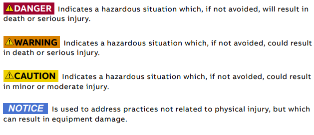
Safety messages The following safety messages are provided to help prevent personal injury and damage to the equipment. The indicated hazard level is based on the ANSI Z535.6 standard.

This is the safety alert symbol. It is used to alert you to potential physical injury hazards. Obey all safety messages that follow this symbol to avoid possible injury or death
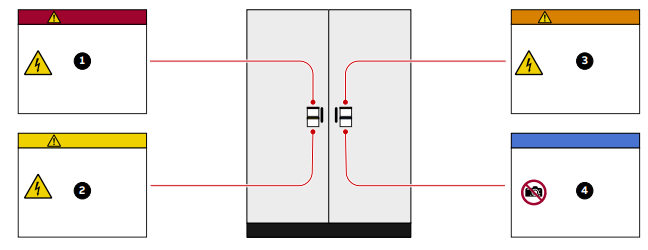
Product safety labels Safety labels are affixed to the drive components to alert personnel of potential hazards when working on the equipment. For more information, see the label placement document for the drive. The instructions on the safety labels must always be followed and the labels must be kept in a perfectly legible condition.
General safety instructions 1) Minimize hazards 2) Before energizing the drive:
• Remove all foreign objects are from the drive
• Fasten all internal and external covers securely
• Close, lock, and/or bolt all doors
• Move the release dial of the door safety switches into the locked position 3) Before working on the drive:
• Turn off, lock out, and tag out the main and auxiliary power supplies to the drive • De-energize the drive
• Ensure that the safety ground connections are in place
• Ensure that the appropriate personal protective equipment (PPE) is available and used when required
• Inform the involved personnel about the potential safety hazards
• Wear hearing protection when a drive is running. 4) Before working simultaneously on the drive and on other drive system equipment:
• Observe the relevant safety codes and standards
• Turn off all energy sources for the equipment
• Ensure that all lockout and tagout devices are in place
• Install barriers around and use appropriate covers on the equipment that is still energized
• Inform the involved personnel about the potential safety hazards 5) In case of fire in the drive room:
• Observe the established rules and regulations for fire safety
• Only allow firefighters with the appropriate PPE to enter the drive room
The 7 steps that save lives ABB’s 7 steps that save lives concept is a series of actions that must take place prior to commencing work on or near electrical installations. 1) Prepare for the work: do an on-site risk assessment or job hazard analysis that considers the limits of approach for shock and arc-flash. • Be in possession of a clear work order to execute the work. • When required, the access or work permit is to be obtained by a person who is authorized for the specific electrical system. • Engage the person responsible for electrical equipment or system to review single-line diagrams, schematics, switching plans, etc. • Ensure the competence of workers. • Check for proper tools for the job. • Determine and select the proper arc-rated Personal Protective Equipment (PPE). • Decide of the appropriate work methods and initiate the Permit To Work (PTW) process. 2) Clearly identify the work location and equipment. • Use your senses (sight, hearing and smell) to identify problem areas. • Define the work area via barriers and barricading and label equipment. • Avoid distractions such as talking or texting on the phone. 3a) Disconnect all sources of supply. • If ABB is responsible for switching and it cannot be done remotely, then the person performing the switching must be properly trained and wearing the proper PPE identified in step 1. • The Person in Charge of Work (PICW) must ensure that switching is performed in the proper manner by witnessing it from a safe distance if present on site or by engaging the person responsible for switching to identify all isolation points. 3b) Secure against reconnection by applying Lockout/Tagout. • Apply Lockout/Tagout (LOTO) to the energy isolation device and if multiple energy isolation devices are involved, then Group LOTO must be implemented with the PICW serving as the Group LOTO Leader.
4) Verify the absence of operating voltage: always test before you touch! Only use properly rated and inspected voltage detection devices and wear proper PPE identified in step 1:
• Test voltage detection device • Test for voltage
• Test voltage detection device It is highly important that the voltage detection device is tested on a known voltage source such as a Proving Unit or by performing an internal self-test, according to the manufacturer’s instructions, before and after testing for the absence of operating voltage. 5) Carry out earthing and short-circuiting.
• Close and lock the earthing switch if the electrical equipment is designed for this purpose or apply portable equipment for earthing and short-circuiting. If this is carried out by the customer, then the PICW must ensure that this equipment is properly earthed as a part of the integration/verification and during step 7 when the PICW walks the PTW. 6) Protect against adjacent live parts and take special precautions when close to bare conductors.
• Determine minimum approach distances, apply screening or shrouding, and when applicable, padlock both cable and busbar shutters.
• If working within the restricted approach boundary or vicinity zone where inadvertent movement could cause contact with live parts, special precautions must be employed, such as the use of the properly rated insulated gloves and tools. 7) Complete the permit to work and “Walk the Permit”. • Check isolation points
• Verify that all circuits are isolated and secured • Ensure all parties are integrated with the Lockout/Tagout
• Check the earths are properly applied • Answer specific questions from the working group
• Ensure the work can proceed without danger
• Complete and verify the “Permit to Work”
Possible residual risks Residual risks must be considered by the drive system integrator and/or plant owner when assessing the hazards of the equipment to personnel. The following risks can pose a hazard to drive system personnel: 1) Electric power equipment generates electro-magnetic fields which can cause a hazard to people with metal implants and / or a pacemaker. 2) Drive system components can move unintentionally when being commissioned, operated, or serviced due to:
• Operation of the equipment outside the scope of the specifications • Incorrectly assembled or installed equipment • Wrongly connected cables • External influence on, or damage of the equipment • Wrong parameter settings • Software errors
• Faulty hardware 3) Hazardous touch voltages can be present on drive system components, which can be caused by:
• Operation of the equipment outside the scope of the specifications
• External influence on, or damage of the equipment
• Induced voltages by external equipment
• Condensation on equipment components, or pollution
• Faulty hardware 4) High temperatures, noise, particles, or gases can be emitted from drive system components caused by:
• Operation of the equipment outside the scope of the specifications
• External influence on or damage of the equipment
• Incorrect parameter settings
• Software errors
• Faulty hardware 5) Hazardous substances can be emitted from drive system components due to incorrect disposal of components
-
 OMRON 3G3XV-A2007 3G3XV-A2007-NEV2
 -
 Omron NJ1019000 NJ1 programable logic controller
 -
 OMRON C120-LK202-EV1/C120LK202EV1
 -
 OMRON C200H-AD003 PLC
 -
 OMRON C200H-CPU23-E COIL 24VDC PLC
 -
 Omron C200HG - C200H-ID212- C200H-OC226 C200HW-BC101 PLC Base Unit
 -
 OMRON C200H-OC222(Output Unit),C200H-PS211(Power Supply Unit),SP001 Module Rack
 -
 OMRON C200H-RT201 PROGRAMMABLE CONTROLLER
 -
 OMRON C200HS-CPU01-E SYSMAC PROGRAMMABLE CONTROLLER
 -
 OMRON C200H-SNT31 C200H Programmable Controllers
 -
 OMRON C200HW-MC402-E Motion control unit
 -
 OMRON C200PC-ISA02-DRM-E PLC ISA bus compatible board card
 -
 OMRON C500-CT012 PLC
 -
 OMRON C500-NC103-E PLC
 -
 OMRON C500-NC222-E PLC
 -
 OMRON C500-PRW05-V1 PLC
 -
 OMRON C500-PRW06 PROGRAMMABLE CONTROLLER
 -
 OMRON C500-PS223-E 3G2A5-PS223-E PLC SYSMAC PROGRAMMABLE CONTROLLER
 -
 OMRON C500-TU001 3G2A5-TU001 PLC PLC
 -
 OMRON C60H-C1DR-DE-V1 Programmable Controllers
 -
 OMRON C60H-C5DR-DE-V1 Programmable Controllers
 -
 OMRON C60H-C6DR-DE-V1 Programmable Controllers
 -
 OMRON CJ1G-CPU44H CPU module
 -
 OMRON CJ1G-CPU45H PLC
 -
 OMRON CJ1M-CPU13-ETN V4.0 PLC PLC
 -
 OMRON CJ1W-AD041-V1 Analog input uni
 -
 OMRON CJ1W-CORT21 PLC module
 -
 OMRON CJ1W-IDP01 Input unit
 -
 OMRON CJ1W-MCH71 - MECHATROLINK-II
 -
 OMRON CJ1W-MD261 Digital I/O
 -
 OMRON CJ1W-NC413 Position control unit
 -
 OMRON CJ1W-NCF71 Position Control Units
 -
 OMRON CJ1W-PTS51 Process Simulation I/O Module
 -
 OMRON CJ1W-PTS52 Process Simulation I/O Module
 -
 OMRON CJ1W-SCU21-V1 PLC
 -
 Omron CJ1W-SCU22 Serial Communication Unit
 -
 OMRON CJ1W-TC001 CJ Series Temperature Control Unit
 -
 Omron CK3W-AX1515N Motion Controller
 -
 Omron CP1E-N60DR-D Compact PLC CPU
 -
 OMRON CP1E-NA20DT1-D PLC PLC
 -
 OMRON CP1H-X40DT-D plc PLC
 -
 OMRON CPM2C-S110C-DRT Interface module
 -
 OMRON CQM1-AD041 PLC
 -
 SAACKE F‑GDSA‑1 / F‑GDSA‑2 Feuerungsautomaten
 -
 SAACKE F-GDSA 143303 Controller SHIPS UPS
 -
 ICS Triplex T8270 Trusted 24 Vdc FanAssembly
 -
 SCHNEIDER M522220000 SA SM_DO16R 16 DIGITAL OUTPUTS MODULE
 -
 LENZ EPL10200-W EPZ-10203 CANPT010W3E
 -
 OMRON CQM1H-ADB21 PLC
 -
OMRON CQM1H-CPU61 PLC
-
 OMRON CQM1H-MAB42 PLC
 -
 OMRON CQM1-TC102 CQM1-TC101 PLC
 -
 OMRON CS1G-CPU44-EV1 PLC
 -
 OMRON CS1G-CPU44H CPU
 -
OMRON CS1H-CPU63-EV1 PLC
-
 OMRON CS1H-CPU66-V1 PLC
 -
 OMRON CS1W-CLK13 PLC communication module
 -
OMRON CS1W-EIP21 PLC
-
 OMRON CS1W-MAD44 PLC PLC
 -
 OMRON CS1W-SCU31-V1 CVM1-BC103 PLC
 -
 Omron CVM1-CPU21-V2 CPU Unit
 -
 OMRON F150-C10E-2 Vision Controller
 -
 OMRON F150-C15E-3 Vision Controller
 -
 OMRON F160-C15E VISION MATE CONTROLLER
 -
 OMRON F500-C10-ETN F500-C15-ETN Vision Sensor
 -
 OMRON F500-VS F500-S1
 -
 OMRON FH-3050 FH Vision Controller
 -
 Omron FQ2-S25050F PLC Smart Camera
 -
 Omron FQM1-MMA22 Motion Module
 -
 OMRON GRT1-TS2P Temperature Module
 -
 OMRON H8PR-24 Cam Positioner
 -
 OMRON IDSC-C1DR-A-E Controller
 -
 OMRON K3HB-HTA-DRT1 Temperature Panel Meter
 -
 Omron KM-N1-FLK Power Detector
 -
 OMRON CJ1G-CPU43H CPU
 -
 OMRON NA5-7W001S-V1 NA5-9W001B-V1 NA5-12W101B-V1 Graphic panel
 -
 OMRON NA5-9W001B-V1 Graphic panel
 -
 OMRON NB10W-TW01B INTERACTIVE DISPLAY
 -
 OMRON NB7W-TW01B +CP1L-EL20DR-D Complete Power Panel
 -
 OMRON NB7W-TX01B INTERACTIVE DISPLAY PLC
 -
 Omron NE1A-SCPU02 Network Controller
 -
 OMRON NA5-7W001B-V1 NA5-7W001S-V1 NA5-9W001B-V1 NA5-12W101B-V1 touch screen
 -
 Omron NS5-SQ00B-V2 NS5-SQ00-V2 NS5-SQ01-V2 NS5-SQ01B-V2 touch display panel
 -
 Omron NJ301-1100 Programmable Logic Controller
 -
 OMRON NJ501-1300 CUP Unit Programmable Controller
 -
 Omron NS12-TS01B-V2 Interactive Display
 -
 OMRON NSJW-ETN21 ETHERNET HMI
 -
 OMRON NT10S-SF121 PLC
 -
 OMRON NT20S-ST121-EV3 Touch Screen
 -
 Omron NX1P2-1140DT-BA Programmable Controller
 -
 OMRON 3G3MV-P10CDT3-E RS422/485 INVERTER BOARD
 -
 Omron C500-ID219 3G2A5-ID219 System Microprocessor
 -
 Omron PLC B7AM-8B16
 -
 OMRON PLC Module CJ1W-AD081-V1
 -
 OMRON R88D-HS10 PLC
 -
OMRON R88D-HT10 plc
-
 OMRON R88D-KN01H-ML2 Servos G5-series
 -
 OMRON R88M-H10030-B plc
 -
 OMRON R88S-H306G plc PLC
 -
 Omron Relay G9SX-GS226-T15-RT
 -
 Omron S8AS-24006N S8AS Smart Power Supply FNIP
 -
 Omron Safety Input Unit NX-SIH400
 -
 OMRON SYSMAC SCY-P1 Sequential Controller
 -
OMRON SYSMAC SCY-P0 13E Sequential Controller
-
 OMRON NS8-TV00B-V2 NS8-TV00-V2 NS8-TV00B-ECV2 NS8-TV00-ECV2 touch display Panel
 -
 Omron V680-CA5D02-V2 Programmable Controller
 -
 OMRON SGDH-04AE-OY Servo Drive
 -
OMRON SGDH-10DE-OY Servo Drive
-
 OMRON SGDS-02A12A PLC + SGMAS-C2ACA21
 -
 OMRON SGMPH-04AAA61D-OY Servo Motor
 -
 Omron ZFV-CA40 Smart Sensor Amp Unit 24VDC 0.8A
 -
OMRON ZFV-NX1 CFP0260 ZFV-A20 VISION CONTROL PANEL
-
 OMRON ZFX-C15 SMART SENSOR AMP UNIT, Vision Sensor LCD
 -
 OMRON ZFX-C20/25-CD SMART SENSOR AMP UNIT, Vision Sensor LCD
 -
 OMRON-DIGITAL TEMPERATURE CONTROLLER E5AC-CX4A5M-014 r
 -
 ABB PFVL141V-2.0MN is an industrial-grade, rectangular roll force load cell
 -
 ABB PFVL141V-1.6MN is an industrial-grade, rectangular roll force load cell
 -
ABB PFVL141V-1.25MN high-performance, rectangular roll force load cell
-
 ABB PFVL141V-1.0MN high-precision, heavy-duty rectangular load cell
 -
 ABB PFVL141V-0.8MN high-precision, heavy-duty rectangular load cell
 -
 ABB PFVL141V-0.63MN high-precision, heavy-duty rectangular load cell
 -
 GE 151X1202YE08PP08 Panel of the case / Structural component
 -
 GE 151X1212HB01MG02 Integrated LCI Controller (Old Model)
 -
 GE 151X1212GC01PC02 LCI Static Startup Controller
 -
 GE 151X1235FD01PK01 High-speed Digital Input Interface Board
 -
 GE 151X1215DK01PC01 Signal Processing / Amplification Board
 -
 GE 151X1238WP99BK01 6-pulse LCI power conversion module
 -
 GE 151X1225DF01PC03RA - Power Conversion / Drive Regulation Board


