WATLOWCLS200, MLS300, and CAS200 Communications Specification
This reference guide is designed to help applications software
programmers with the following tasks:
• Interface to Watlow Anafaze MLS300, CLS200, MLS and CLS controllers, and the CAS200 and CAS scanners via serial communications.
• Modify the communications Anafaze protocol driver in the Watlow
Anafaze Communications Driver Kit. (If you have the communications driver kit, you don’t need to read this manual unless you want
to modify the communications driver.)
In This Manual
The following sections are included in this guide:
Chapter 1: Anafaze/AB Protocol. Gives an overview and explanation
of the Anafaze/Allen Bradley communications protocol.
Chapter 2: Modbus-RTU Protocol. Gives an overview and
explanation of the Modbus-RTU communications protocol
Chapters 1 and 2: Data Table Summary. Provides standard controller
data table maps for the parameters (one for each protocol).
Chapter 3: Parameters Description. Describes each parameter.
Appendix A: Communications driver.
Glossary: Explanation of commonly used terms and acronyms.
NOTE
This reference guide is not a tutorial. It does not explain
how to use the controller; it is not a programming reference; it also does not explain PID control, alarms, linear
scaling, or other topics that are explained in detail in the
controller manuals. If you need additional information
about a topic covered in this reference guide, consult the
documentation included with your controller.
Chapter 1: ANAFAZE/AB Protocol
This section explains the ANAFAZE/Allen Bradley protocol used in
Watlow Anafaze MLS, CLS, and CAS devices. These controllers
operate on serial communications links (EIA/TIA-232 or EIA-TIA-485)
at either 2400 or 9600 baud. They use 8 data bits, one or 2 stop bits, and
no parity.
Protocol Syntax
The controllers use a half-duplex (master-slave) protocol to interface to
high-level software. The host software is considered the “master” and
the controller is considered the “slave.” In other words, the software can
request information from the controller or download information to the
controller. The controller can only respond to communications
transactions initiated by the host software. The controller cannot initiate
communications.
The controller and host software communicate by sending and receiving
information in a “packet” format. A packet consists of a sequence of
bytes in a specific format; it can be as large as 256 bytes of data. (For
more information about packets, see the Packet Format section later in
this chapter.)
The numbers in the packet are sent in binary format. However, our
examples show bytes in hexadecimal format.
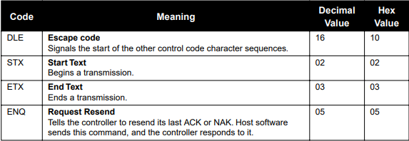
Control Codes
Watlow Anafaze abbreviates control codes this way

Chapter 1: ANAFAZE/AB Protocol

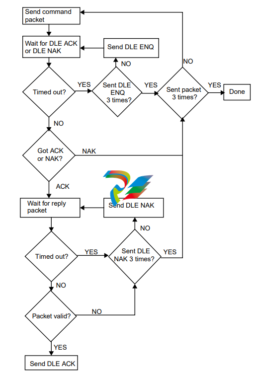
Transaction Sequence
Here are the four steps in a transaction between the host software and
the controller. The following example shows the transaction as an
exchange of packets. The example also assumes that there are no
communication errors in the exchange.
(1) The host software sends a packet that contains a read command or
write command.
(2) The controller sends a DLE ACK to the host software.
(3) The host software receives a reply packet from the controller.
(4) The host software sends a DLE ACK.
The following flowchart shows a transaction with no error handling.

NOTE
Due to the difference between the processing speeds of the
controller and PCs, it may be necessary to delay the computer's acknowledgement (ACK) in order for the controller
to receive it. A delay of 200 ms should suffice

Packet Format
Messages are transmitted in the form of packets. Command and reply
packets specify the source and destination addresses, whether to read or
write, the block of data to read or write, etc.
A packet contains a sequence of binary bytes formatted this way:
Sending Control Codes
To send a control code, send a DLE before the control code to
distinguish it from data.
Sending a DLE as Data
When you send a byte with an x10, (a DLE), the controller and software
interpret it as a command. Therefore, to send a DLE as data, send
another DLE immediately before it (DLE DLE).
Codes in a Packet
This section describes the sequence of bytes in a packet, in the order the
host software or controller sends them.
DLE STX
• The DLE STX byte signals the beginning of a transmission. Every
packet of information starts with the control codes DLE STX.
DST
• The DST byte is the address of the destination device (usually a controller; the first Watlow Anafaze controller is at x08).
NOTE
When host software communicates with an MLS, a CLS, or
a CAS in ANAFAZE or AB protocol, it does not send the
controller’s actual address. Since the protocol reserves
device addresses 0 to 7, the host software sends the value
(controller address + 7), instead of the actual device
address.
SRC
• The SRC byte is the device address of the packet’s source. The host
software is usually designated address x00.
DLE STX DLE ETX BCC/CRC
DST SRC CMD STS TNSL TNSH ADDL ADDH DAT
CMD
• The CMD byte indicates the command that the host software sends
to the controller. The software sends a read (x01) or write (x08).
When the controller replies, it returns the read or write command


