
ABBDCS880Hardware manual DCS880 Drives (20 A ... 5200 A)
Safety instructions What this chapter contains
y instructions What this chapter contains
This chapter contains the safety instructions which you must follow when installing, operating and servicing the drive. If ignored, physical injury or death may follow, or damage may occur to the drive, the motor or driven equipment. Read the safety instructions before you work on the unit.
To which products this chapter applies
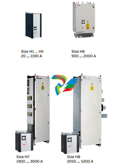
The information is valid for the whole range of the product DCS880, the converter modules DCS880-S0x size H1 ... H8, field exciter units DCF80x, etc. like the Rebuild Kit DCS880-R00.
Use of warnings and notes
There are two types of safety instructions throughout this manual: warnings and notes. Warnings caution you about conditions which can result in serious injury or death and/or damage to the equipment and advice on how to avoid the danger. Notes draw attention to a particular condition or fact, or give information on a subject. The warning symbols are used as follows:

Dangerous voltage warning warns of high voltage which can cause physical injury and/or damage to the equipment. General danger warning warns about conditions, other than those caused by electricity, which can result in physical injury or death and/or damage to the equipment. Electrostatic sensitive discharge warning warns of electrostatic discharge which can damage the equipment
Installation and maintenance work These warnings are intended for all who work on the drive, motor cable or motor. Ignoring the instructions can cause physical injury or death and/or damage to the equipment.
WARNING – Only qualified electricians are allowed to install and maintain the drive! – Never work on the drive, motor cable or motor when main power is applied. – Always ensure by measuring with a multimeter (impedance at least 1 MOhm) that: Voltage between drive input phases U1, V1 and W1 and the frame is close to 0 V. Voltage between terminals C+ and D- and the frame is close to 0 V. – Do not work on the control cables when power is applied to the drive or to the external control circuits. Externally supplied control circuits may cause dangerous voltages inside the drive even when the main power on the drive is switched off. – Do not make any insulation resistance or voltage withstand tests on the drive or drive modules. – Isolate the motor cables from the drive when testing the insulation resistance or voltage withstand of the cables or the motor. – When reconnecting the motor cable, always check that the C+ and D- cables are connected with the proper terminal.
Notes: – The motor cable terminals on the drive are at a dangerously high voltage when the main power is on, regardless of whether the motor is running or not. – Depending on the external wiring, dangerous voltages (115 V, 220 V or 230 V) may be present on the relay outputs of the drive system (e.g. XRO1 ... XRO3). – DCS880 with enclosure extension: Before working on the drive, isolate the whole drive from the supply.
Grounding
These instructions are intended for all who are responsible for the grounding of the drive. Incorrect
grounding can cause physical injury, death and/or equipment malfunction and increase
electromagnetic interference
WARNING – Ground the drive, motor and adjoining equipment to ensure personnel safety in all circumstances, and to reduce electromagnetic emission and pick-up. – Make sure that grounding conductors are adequately sized and marked as required by safety regulations. – In a multiple-drive installation, connect each drive separately to protective earth (PE ). – Minimize EMC emission and make a 360° high frequency grounding (e.g. conductive sleeves) of screened cable entries at the cabinet lead-through plate. – Do not install a drive equipped with an EMC filter to an ungrounded power system or a high resistance-grounded (> 30 Ohms) power system.
Notes: – Power cable shields are suitable as equipment grounding conductors only when adequately sized to meet safety regulations. – As the normal leakage current of the drive is higher than 3.5 mAAC or 10 mADC, a fixed protective earth connection is required. – This product can cause a DC current in the protective earthing conductor. Where a residual current-operated protective (RCD) or monitoring (RCM) device is used for protection in case of direct or indirect contact, only an RCD or RCM of Type B is allowed on the supply side of this product.
Printed circuit boards and fiber optic cables These instructions are intended for all who handle the circuit boards and fiber optic cables. Ignoring the following instructions can cause damage to the equipment.
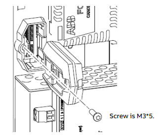
WARNING – The printed circuit boards contain components sensitive to electrostatic discharge. Wear a grounding wrist band when handling the boards. Do not touch the boards unnecessarily. – Use grounding strip:

WARNING – Handle the fiber optic cables with care. The minimum allowed bend radius is 35 mm (1.38 in.). – When unplugging optic cables, always grab the connector, not the cable itself. – Do not touch the ends of the fibers with bare hands as the fiber is extremely sensitive to dirt.
Mechanical installation These notes are intended for all who install the drive. Handle the unit carefully to avoid damage and injury.
WARNING – DCS880 sizes H4 ... H8: – The drive is heavy. Lift the drive by lifting lugs only. – The drive’s center of gravity is high. Do not tilt the unit. The unit will overturn from a tilt of about 6 degrees. An overturning drive can cause physical injury. – Do not lift the unit by the front cover. – Place units H4 … H6 only on their back. – Make sure that dust from drilling does not enter the drive when installing. Electrically conductive dust inside the unit may cause damage or lead to malfunction. – Ensure sufficient cooling. – Do not fasten the drive by riveting or welding
Operation
These warnings are intended for all who plan the operation of the drive or operate the drive. Ignoring the instructions can cause physical injury or death and/or damage to the equipment.
WARNING – Before adjusting the drive and putting it into service, make sure that the motor and all driven equipment are suitable for operation throughout the speed range provided by the drive. The drive can be adjusted to operate the motor at speeds above and below the base speed. – Do not control the motor with the disconnecting device (disconnecting mains); instead, use the control panel keys and , or commands via the I/O board of the drive. – Mains connection: You can use a disconnect switch (with fuses) to disconnect the electrical components of the drive from the mains for installation and maintenance work. The type of disconnect switch used must be as per EN 60947-3, Class B, so as to comply with EU regulations, or a circuit-breaker type which switches off the load circuit by means of an auxiliary contact causing the breaker's main contacts to open. The mains disconnect must be locked in its "OPEN" position during any installation and maintenance work. – EMERGENCY STOP buttons must be installed at each control desk and at all other control panels requiring an emergency stop function. Pressing the STOP button on the control panel of the drive will neither cause an emergency stop of the motor, nor will the drive be disconnected from any dangerous potential. – To avoid unintentional operating states, or to shut the unit down in case of any imminent danger according to the standards in the safety instructions it is not sufficient to merely shut down the drive via signals "RUN", "drive OFF" or "Emergency Stop" respectively "control panel" or "PC tool". – Intended use: The operating instructions cannot take into consideration every possible case of configuration, operation or maintenance. Thus, they mainly give such advice only, which is required by qualified personnel for normal operation of the machines and devices in industrial installations. If in special cases the electrical machines and devices are intended for use in non-industrial installations - which may require stricter safety regulations (e.g. protection against contact by children or similar) - these additional safety measures for the installation must be provided by the customer during assembly.
Note: – When the control location is not set to Local (Local not shown in the status row of the display), the stop key on the control panel will not stop the drive. To stop the drive using the control panel, press the Loc/Rem key and then the stop key
The DCS880 Chapter overview This chapter describes briefly the operating principle and construction of the converter modules in short. The DCS880 converter modules The DCS880-S size H1 ... H8 are intended for controlling DC motors.
Mechanical installation Chapter overview This chapter describes the mechanical installation of the DCS880. Safety
WARNING Examining the installation site The drive must be installed in an upright position with the cooling section against a wall. Make sure that the installation site agrees with these requirements: – The installation site has sufficient ventilation to prevent overheating of the drive. See chapter Current ratings. – The operation conditions of the drive agree with the specifications in chapter Environmental Conditions. – The wall is vertical, not flammable and strong enough to hold the weight of the drive. – The material below the installation is not flammable. – There is enough free space above, beside and belo
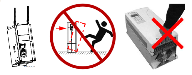
w the drive for cooling air flow, service and maintenance. There is enough free space in front of the drive for operation, service and maintenance. See chapter Dimensions and weights. Necessary tools – Drill and drill bits. – Screwdriver and/or wrench with bits. Some drive covers have torx screws. Moving the drive Move the transport package by pallet truck to the installation site. – DCS800 sizes H4 ... H8: – The drive is heavy. Lift the drive by lifting lugs only. – The drive’s center of gravity is high. Do not tilt the unit. The unit will overturn from a tilt of about 6 degrees. An overturning drive can cause physical injury. – Do not lift the unit by the front cover. Place units H4 … H6 only on their back
Delivery check Check that there are no signs of damage. Before attempting installation and operation, check the information on the nameplate of the converter module to verify that the unit is of the correct type. The label includes an IEC rating, cTÜVus, C-tick (N713) and CE markings, a type code and a serial number, which allow individual identification of each unit. The remaining digits complete the serial number so that there are no two units with the same serial number. See an example nameplate below.
Replacing the memory unit Make sure, that the auxiliary power is off. Unscrew the memory unit and pull it out. Replace the memory unit in reverse order.
Additional terminals
– Use connectors Slot1 … Slot3 for F-type I/O extension modules and F-type fieldbus adapters.
– Connectors XC12, XS13, X14 and X38 connect the SDCS-CON-H01 to the SDCS-PIN-H01 or SDCS-POW-H01 for
voltage, current, temperature measurement and safety.
– Use connector X13 to connect the control panel either directly via a jack plug or via a CAT 1:1 cable (< 3 m)
with RJ-45 plugs.
-
 OMRON 3G3XV-A2007 3G3XV-A2007-NEV2
 -
 Omron NJ1019000 NJ1 programable logic controller
 -
 OMRON C120-LK202-EV1/C120LK202EV1
 -
 OMRON C200H-AD003 PLC
 -
 OMRON C200H-CPU23-E COIL 24VDC PLC
 -
 Omron C200HG - C200H-ID212- C200H-OC226 C200HW-BC101 PLC Base Unit
 -
 OMRON C200H-OC222(Output Unit),C200H-PS211(Power Supply Unit),SP001 Module Rack
 -
 OMRON C200H-RT201 PROGRAMMABLE CONTROLLER
 -
 OMRON C200HS-CPU01-E SYSMAC PROGRAMMABLE CONTROLLER
 -
 OMRON C200H-SNT31 C200H Programmable Controllers
 -
 OMRON C200HW-MC402-E Motion control unit
 -
 OMRON C200PC-ISA02-DRM-E PLC ISA bus compatible board card
 -
 OMRON C500-CT012 PLC
 -
 OMRON C500-NC103-E PLC
 -
 OMRON C500-NC222-E PLC
 -
 OMRON C500-PRW05-V1 PLC
 -
 OMRON C500-PRW06 PROGRAMMABLE CONTROLLER
 -
 OMRON C500-PS223-E 3G2A5-PS223-E PLC SYSMAC PROGRAMMABLE CONTROLLER
 -
 OMRON C500-TU001 3G2A5-TU001 PLC PLC
 -
 OMRON C60H-C1DR-DE-V1 Programmable Controllers
 -
 OMRON C60H-C5DR-DE-V1 Programmable Controllers
 -
 OMRON C60H-C6DR-DE-V1 Programmable Controllers
 -
 OMRON CJ1G-CPU44H CPU module
 -
 OMRON CJ1G-CPU45H PLC
 -
 OMRON CJ1M-CPU13-ETN V4.0 PLC PLC
 -
 OMRON CJ1W-AD041-V1 Analog input uni
 -
 OMRON CJ1W-CORT21 PLC module
 -
 OMRON CJ1W-IDP01 Input unit
 -
 OMRON CJ1W-MCH71 - MECHATROLINK-II
 -
 OMRON CJ1W-MD261 Digital I/O
 -
 OMRON CJ1W-NC413 Position control unit
 -
 OMRON CJ1W-NCF71 Position Control Units
 -
 OMRON CJ1W-PTS51 Process Simulation I/O Module
 -
 OMRON CJ1W-PTS52 Process Simulation I/O Module
 -
 OMRON CJ1W-SCU21-V1 PLC
 -
 Omron CJ1W-SCU22 Serial Communication Unit
 -
 OMRON CJ1W-TC001 CJ Series Temperature Control Unit
 -
 Omron CK3W-AX1515N Motion Controller
 -
 Omron CP1E-N60DR-D Compact PLC CPU
 -
 OMRON CP1E-NA20DT1-D PLC PLC
 -
 OMRON CP1H-X40DT-D plc PLC
 -
 OMRON CPM2C-S110C-DRT Interface module
 -
 OMRON CQM1-AD041 PLC
 -
 SAACKE F‑GDSA‑1 / F‑GDSA‑2 Feuerungsautomaten
 -
 SAACKE F-GDSA 143303 Controller SHIPS UPS
 -
 ICS Triplex T8270 Trusted 24 Vdc FanAssembly
 -
 SCHNEIDER M522220000 SA SM_DO16R 16 DIGITAL OUTPUTS MODULE
 -
 LENZ EPL10200-W EPZ-10203 CANPT010W3E
 -
 OMRON CQM1H-ADB21 PLC
 -
OMRON CQM1H-CPU61 PLC
-
 OMRON CQM1H-MAB42 PLC
 -
 OMRON CQM1-TC102 CQM1-TC101 PLC
 -
 OMRON CS1G-CPU44-EV1 PLC
 -
 OMRON CS1G-CPU44H CPU
 -
OMRON CS1H-CPU63-EV1 PLC
-
 OMRON CS1H-CPU66-V1 PLC
 -
 OMRON CS1W-CLK13 PLC communication module
 -
OMRON CS1W-EIP21 PLC
-
 OMRON CS1W-MAD44 PLC PLC
 -
 OMRON CS1W-SCU31-V1 CVM1-BC103 PLC
 -
 Omron CVM1-CPU21-V2 CPU Unit
 -
 OMRON F150-C10E-2 Vision Controller
 -
 OMRON F150-C15E-3 Vision Controller
 -
 OMRON F160-C15E VISION MATE CONTROLLER
 -
 OMRON F500-C10-ETN F500-C15-ETN Vision Sensor
 -
 OMRON F500-VS F500-S1
 -
 OMRON FH-3050 FH Vision Controller
 -
 Omron FQ2-S25050F PLC Smart Camera
 -
 Omron FQM1-MMA22 Motion Module
 -
 OMRON GRT1-TS2P Temperature Module
 -
 OMRON H8PR-24 Cam Positioner
 -
 OMRON IDSC-C1DR-A-E Controller
 -
 OMRON K3HB-HTA-DRT1 Temperature Panel Meter
 -
 Omron KM-N1-FLK Power Detector
 -
 OMRON CJ1G-CPU43H CPU
 -
 OMRON NA5-7W001S-V1 NA5-9W001B-V1 NA5-12W101B-V1 Graphic panel
 -
 OMRON NA5-9W001B-V1 Graphic panel
 -
 OMRON NB10W-TW01B INTERACTIVE DISPLAY
 -
 OMRON NB7W-TW01B +CP1L-EL20DR-D Complete Power Panel
 -
 OMRON NB7W-TX01B INTERACTIVE DISPLAY PLC
 -
 Omron NE1A-SCPU02 Network Controller
 -
 OMRON NA5-7W001B-V1 NA5-7W001S-V1 NA5-9W001B-V1 NA5-12W101B-V1 touch screen
 -
 Omron NS5-SQ00B-V2 NS5-SQ00-V2 NS5-SQ01-V2 NS5-SQ01B-V2 touch display panel
 -
 Omron NJ301-1100 Programmable Logic Controller
 -
 OMRON NJ501-1300 CUP Unit Programmable Controller
 -
 Omron NS12-TS01B-V2 Interactive Display
 -
 OMRON NSJW-ETN21 ETHERNET HMI
 -
 OMRON NT10S-SF121 PLC
 -
 OMRON NT20S-ST121-EV3 Touch Screen
 -
 Omron NX1P2-1140DT-BA Programmable Controller
 -
 OMRON 3G3MV-P10CDT3-E RS422/485 INVERTER BOARD
 -
 Omron C500-ID219 3G2A5-ID219 System Microprocessor
 -
 Omron PLC B7AM-8B16
 -
 OMRON PLC Module CJ1W-AD081-V1
 -
 OMRON R88D-HS10 PLC
 -
OMRON R88D-HT10 plc
-
 OMRON R88D-KN01H-ML2 Servos G5-series
 -
 OMRON R88M-H10030-B plc
 -
 OMRON R88S-H306G plc PLC
 -
 Omron Relay G9SX-GS226-T15-RT
 -
 Omron S8AS-24006N S8AS Smart Power Supply FNIP
 -
 Omron Safety Input Unit NX-SIH400
 -
 OMRON SYSMAC SCY-P1 Sequential Controller
 -
OMRON SYSMAC SCY-P0 13E Sequential Controller
-
 OMRON NS8-TV00B-V2 NS8-TV00-V2 NS8-TV00B-ECV2 NS8-TV00-ECV2 touch display Panel
 -
 Omron V680-CA5D02-V2 Programmable Controller
 -
 OMRON SGDH-04AE-OY Servo Drive
 -
OMRON SGDH-10DE-OY Servo Drive
-
 OMRON SGDS-02A12A PLC + SGMAS-C2ACA21
 -
 OMRON SGMPH-04AAA61D-OY Servo Motor
 -
 Omron ZFV-CA40 Smart Sensor Amp Unit 24VDC 0.8A
 -
OMRON ZFV-NX1 CFP0260 ZFV-A20 VISION CONTROL PANEL
-
 OMRON ZFX-C15 SMART SENSOR AMP UNIT, Vision Sensor LCD
 -
 OMRON ZFX-C20/25-CD SMART SENSOR AMP UNIT, Vision Sensor LCD
 -
 OMRON-DIGITAL TEMPERATURE CONTROLLER E5AC-CX4A5M-014 r
 -
 ABB PFVL141V-2.0MN is an industrial-grade, rectangular roll force load cell
 -
 ABB PFVL141V-1.6MN is an industrial-grade, rectangular roll force load cell
 -
ABB PFVL141V-1.25MN high-performance, rectangular roll force load cell
-
 ABB PFVL141V-1.0MN high-precision, heavy-duty rectangular load cell
 -
 ABB PFVL141V-0.8MN high-precision, heavy-duty rectangular load cell
 -
 ABB PFVL141V-0.63MN high-precision, heavy-duty rectangular load cell
 -
 GE 151X1202YE08PP08 Panel of the case / Structural component
 -
 GE 151X1212HB01MG02 Integrated LCI Controller (Old Model)
 -
 GE 151X1212GC01PC02 LCI Static Startup Controller
 -
 GE 151X1235FD01PK01 High-speed Digital Input Interface Board
 -
 GE 151X1215DK01PC01 Signal Processing / Amplification Board
 -
 GE 151X1238WP99BK01 6-pulse LCI power conversion module
 -
 GE 151X1225DF01PC03RA - Power Conversion / Drive Regulation Board


