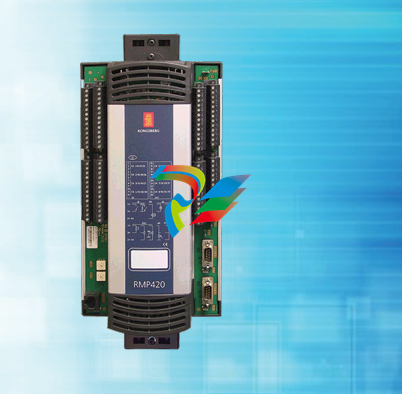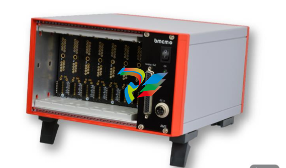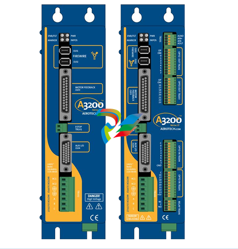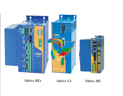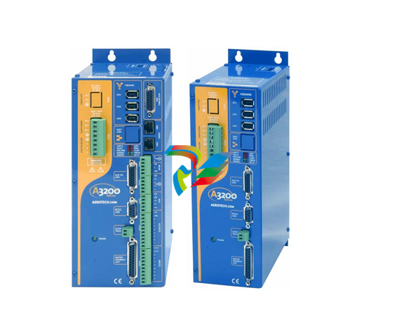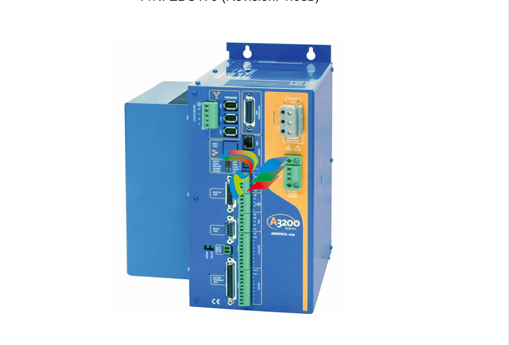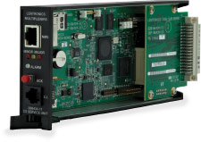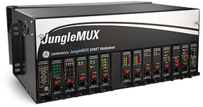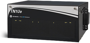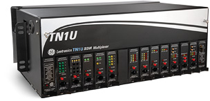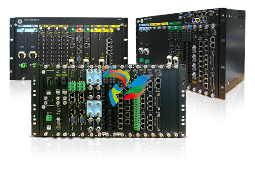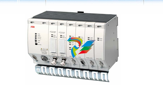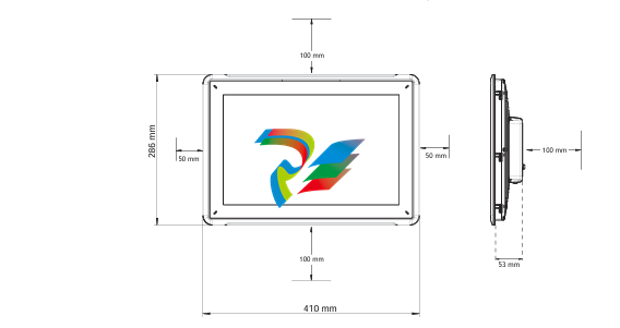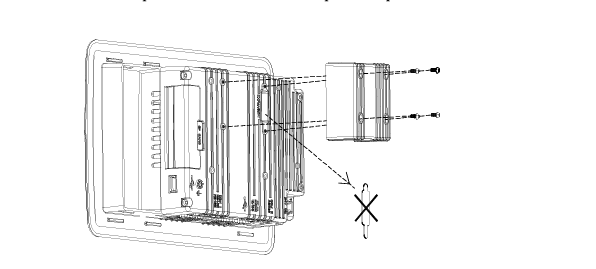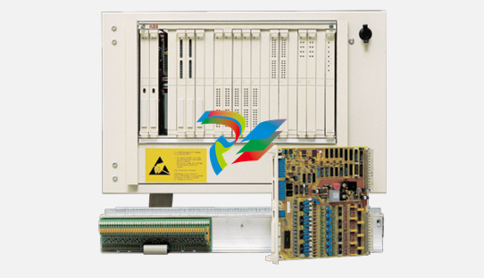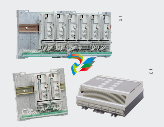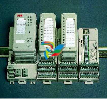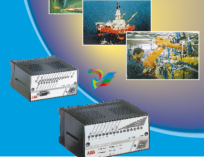
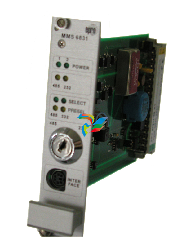
EPRO MMS6210 Dual-channel axial displacement measurement module
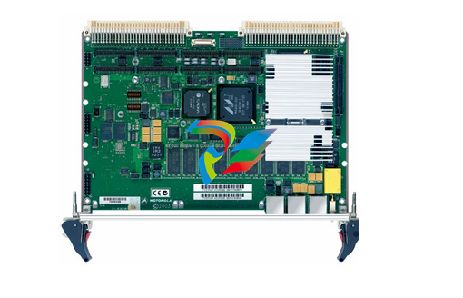
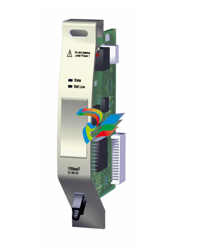
MMS6210 Dual-channel axial displacement measurement module MMS6210
Features
Dual-channel axial displacement measurement module, monitoring axial displacement and expansion difference.
It can be replaced during operation, used independently, and has redundant power input.
Extended self-checking function, built-in sensor self-checking function, password protection operation level.
Applicable eddy current sensor PR642. Series plus preamplifier CON0X1
The RS232/485 ports are used for on-site configuration and communication, and measurement values can be read out.
Built-in linearization processor.
Record and store the measurement data of the most recent start/stop.
Application
The dual-channel axial displacement measurement module MMS6210 measures the movement of shafts, such as: axial displacement,
expansion difference, thermal expansion, and radial shaft position. The signal is taken from the eddy current displacement sensor.
The measurement of this module can be combined with that of other modules to form a turbomachinometer protection system,
or be provided as input to the analysis and diagnosis system, fieldbus system, distributed control system, power plant/main computer, network such as WAN/LAN network, Ethernet.
For steam engines, gas engines, water turbines, compressors, fans, centrifuges and other turbomachinery.
The use of this system can enhance the efficiency of operation, the safety of operation and extend the service life of machinery.
The MMS6210 is a dual-channel axial displacement measurement module that can use eddy current displacement sensors to measure axial movement to monitor and protect various types of turbine machinery,
such as steam turbines, gas turbines, compressors, fans, gearboxes, blowers, centrifuges, etc.
The output of the sensor, that is, the input of the module, represents the gap from the front end of the sensor to the surface of the object being measured.
The signal is processed by the MMS6210 module and converted into a standard signal output in proportion to the set working mode.
The other parts of the module provide functions such as alarm, sensor power supply, module power supply, detection of channels and sensors, and signal filtering.
It is equipped with a built-in microprocessor, allowing the working mode and parameters to be set and all measurement values to be read via on-site portable devices or remote communication buses.
The last start/stop process is stored in the module and can be displayed on the computer.
Signal input
a." The MMS6210 has two independent eddy current sensor signal inputs:
SENS 1H (z8) /SENS 1L (z10) and SENS 2H (d8) /SENS 2L (d10).
The matching eddy current sensor is the PR642X series eddy current sensor and the corresponding preamplifier produced by the German company epro.
Sensors of the same type produced by other manufacturers can also be used. The input voltage range is -1... -22 V dc.
The module provides two -26.75V DC power supplies for the sensor:
SENS 1+ (z6) /SENS 1- (b6) and SENS 2+ (d6) /SENS 2- (b8).
The sensor signal can be detected at the SMB interface on the front panel of the module.
b." The module has two voltage inputs, EI1 (b14)/EI2 (b16), and their functions will be introduced in the next chapter.
c. The module is also equipped with a key signal input (must be greater than 13V), which is necessary for the speed control mode.
2. Signal output
a." Output of characteristic values
The module has two current outputs representing characteristic values: I1+ (z18)/I1- (b18) and I2+ (z20)/I2- (b20), which can be set to 0... 20mA or 4... 20mA.
The module has two zeros representing the eigenvalues... 10V voltage output: EO 1 (d14)/EO 2 (d16).
b." The module provides two paths of 0... 10 V dc voltage output: NGL1 (z12)/NGL2 (d12).
This output is proportional to the distance between the sensor and the measured surface.
3. Limit monitoring
a." Alarm value
In the dual-channel independent measurement mode, each channel can be separately set with two sets of alarm values and danger values.
The specific description of the dual-channel combined use mode is provided later.
To prevent repeated alarms triggered by changes in the measured value near the limit value, an alarm lag value can be set at 1... of the full scale. Choose between 20%.
b." Limit multiplier and multiplier coefficient X
In special circumstances, such as when the critical speed is exceeded, to avoid unnecessary alarms or trips,
the limit multiplier function can be activated in the software and the multiplier coefficient X (1.00 to 5.00) can be set. When using this function,
d18 should be at a low level. The multiplication coefficient X simultaneously affects both the alarm value and the danger value.
c. Alarm output
The module provides four alarm outputs:
Channel 1: Danger D1-C, D1-E (d26. d28), Alarm A1-C, A1-E (b26. b28)
Channel 2: Danger D2-C, D2-E (d30. d32), Alarm A2-C, A2-E (b30. b32)
Whether the alarm is triggered upwards or downwards, an alarm output will be given.
"d. Alarm hold function
By using this function, the alarm status will be maintained. Only through the Reset latch channel 1/2 command in the software can the alarm be cancelled after the alarm condition disappears.
e." Alarm output mode
When using SC-A (Alarm d24) and SC-D (Danger z24), the alarm output mode can be selected:
When SC- is an open circuit or a high potential (+ 24V), the alarm output is normally open.
When SC- is at a low potential (0 V), the alarm relay is normally closed.
To avoid power failure causing an alarm and facilitate plugging and unplugging while powered on, it is recommended to choose an alarm output that is always on.
f." No alarm allowed
The alarm output will be disabled in the following circumstances:
- Module failure (power supply or software failure).
The delay period after power-on and the 78-second delay period after power-off and setting.
The module temperature exceeds the dangerous value.
- Disable the external alarm and set ES (z22) to 0V.
When the limit suppression function is activated, the input level is 0.5V lower than the lower limit of the range or 0.5V higher than the upper limit of the range.
4. Status monitoring
The module continuously checks the measurement circuit, provides indications when faults are detected, and locks the alarm output when necessary.
There are three ways for status indication:
- Through the "Channel Normal" indicator light on the front panel;
- Output 1/2 through "Channel Normal";
- Displayed on Device status via computer and configuration software.
a." Channel monitoring
The module checks the DC voltage value of the input signal. When the input signal exceeds the set upper limit of 0.5V or falls below the set lower limit of 0.5V,
a channel error indication (sensor short circuit or open circuit) is given.
b." Normal channel indication
When the channel is normal, the indicator light is green.
The changes of the indicator light are as follows:
- The indicator light is off... "Fault
-Slow flicker (FS) 0.8Hz... Channel status
- Fast Flash (FQ) 1.6Hz... Module status
After being powered on
- Normal startup period... The two indicator lights flash synchronously for 15 seconds.
- The module is not configured... The two indicator lights flash alternately.
- Module not calibrated *... All the indicator lights flash alternately. When this phenomenon occurs, it should be sent to the factory for handling.
| User name | Member Level | Quantity | Specification | Purchase Date |
|---|


