
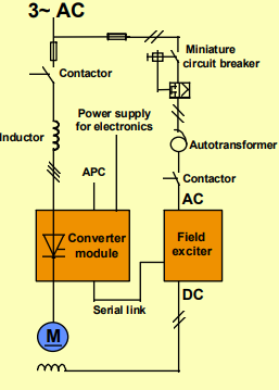
ABBDCV 700 thyristor panelsfor 6-/ and 12-pulse DC drive systems in Drive-MNS-cabinets 22 to 5150/10300 A 10 to 4900/9400 kW
Control Configuration The control system provides a flexible and simple method of controlling different drive configurations. The configurations comprise the converter and its software, Application Controller, Engineering and Maintenance tools and different communication links to other automation systems. The control system includes an Application Controller (APC) and a Digital Drive Controller (DDC) with well defined functions and interface. The Application Controller (APC), common for both AC and DC drives, is a single board controller with all the software and hardware facilities needed to handle the application specific functions. The Digital Drive Controller (DDC) is not programmable but various functions and operating modes can be selected by a fixed number of parameters, which are set from the APC level. The motor control programs are located in the DDC, which is controlled by either a torque or a speed reference provided by the APC.
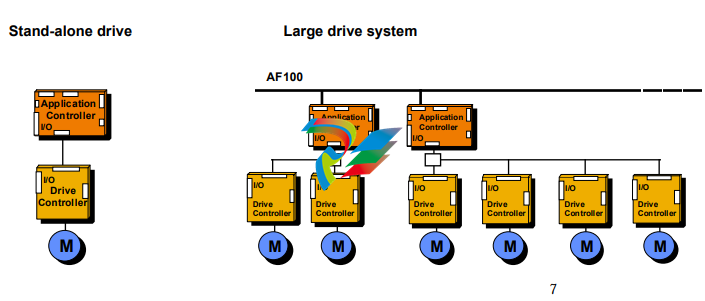
Stand-alone drive A single drive has one Digital Drive Controller DDC connected to the Application controller APC. Small drive system In small systems, one APC is connected from 1 up to 4 Digital Drive Controllers. The small drive configuration can also be used in master/slave applications. Large drive system Large systems are built by interconnecting application controllers through a communication bus, for example AF100. Common control functions can be distributed to separate nodes. Even very complex systems can be configured by using the same system design concept and its common building blocks, resulting in great savings in, for example, spare parts.
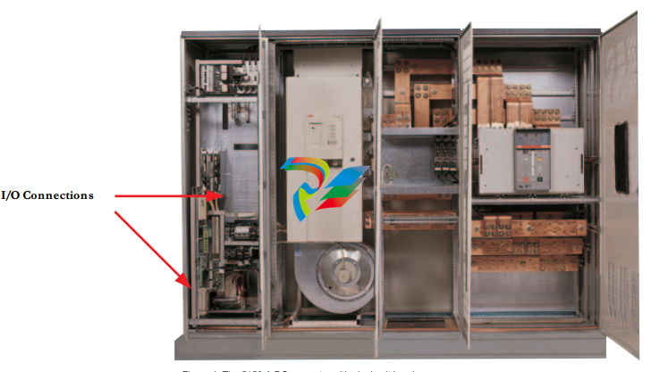
The I/O connections of the DCV 700 are in the Application Controller (APC) and in the Digital Drive Controller (DDC). The Application Controller APC includes: • 4 digital inputs • 2 digital outputs • 2 analogue inputs • 1 voltage reference output The I/O connections in the Drive Controller DDC are used for safety and other drive specific functions like emergency stop and motor temperature measurement: • 3 digital inputs • 4 digital outputs • 5 analogue inputs • 2 analogue outputs • 1 pulse encoder input • 1 emergency stop input • 1 emergency stop output • 1 current source • 1 voltage reference output • 1 actual armature current output Optional I/O boards are available to provide tailored solutions for the most demanding applications. The quantity of I/Os can be increased by using extended I/O board and speed measurement board. Extended / Remote I/O Board YPQ110A Connection to the APC can either be through parallel bus (extended) or through low speed serial bus (remote). • 8 digital inputs • 8 digital outputs • 4 analogue inputs • 2 analogue outputs • 3 voltage reference outputs Speed Measurement Board YPH107A The board can be used for accurate speed and position measurement. Connection to the APC is through the parallel bus. For positioning there is a 32 bit hardware counter. • 1 digital input for synchronisation • 1 pulse encoder input • 2 analogue outputs
Communication Various communication boards are available to provide communication links between the APC and overriding control systems.
AF100 Advant Fieldbus 100 is a high-speed serial bus, which is used for communication between APCs or between an APC and an overriding system such as ABB’s Advant Controller AC400-family. The bus administrator board CI626 (BA) is needed for controlling the bus when not using the Advant Controller AC450. The communication board YPK112A is used to connect the APC to the Advant Fieldbus 100.
UART Board YPK113A The UART board, YPK113A, is used to communicate with other overriding systems. Protocols for Siemens Simatic S5 and Allen Bradley DH are available together with SAMI protocol.
Technical Data Optional I/O Connections The technical data and dimensions are valid at the time of printing. We reserve the right to subsequent alterations. Extended/Remote I/O board YPQ110A
8 digital inputs Opto isolated inputs, control voltage 110 VAC/ 24 VDC. Hardware delay 2 ms. Digital filter time constants from 0.5 ms to 128 ms in 0.5 ms steps. Input impedance 3 kΩ for 24 VDC and 13 kΩ for 110 VAC. 8 digital outputs 6 relay outputs, normally open contacts. Max. voltage 230 VAC, max. current 2 A at 230 VAC, min. switching time 20 ms. 2 opto isolated transistor outputs. Max. voltage 60 V DC, max. current 100 mA, min. switching time 100 µs. 4 analogue inputs Differential inputs, resolution 12 bits+sign. Input ranges -10 to +10 V or -20 to +20 mA (0 to +10 V, 0 to +1 V and 0/4 to 20 mA by software scaling), input impedance is 400 kΩ. Accuracy ± 0.1 % at ± 10 V and ± 0.4 % at ± 1 V. Hardware filter time constant 5 ms. Digital filter time constants from 5 ms to 32 s in 1 ms steps. 2 analogue outputs Output voltage -10 to +10 V, output current -10 to +10 mA. Resolution 12 bits+sign, accuracy ± 0.1 %. 3 voltage reference +10 V voltage reference, accuracy ± 1 mV. outputs Max. load current 10 mA. -10 V voltage reference, accuracy ± 5 mV. Max. load current 10 mA. 5 mA current reference, accuracy ± 0.05 mA. Max. load resistance 1 kΩ. Extended, connection through parallel bus: max. 4 boards. Remote, connection through low speed serial bus: max. 8 nodes. Speed measurement board YPH107A 1 digital input for Control voltage 24 V AC/DC or 110 V AC/DC. synchronisation Input impedance 3 kΩ at 24 V and 13 kΩ at 110 V. Hardware delay 1 ms or 10 ms, software adjustable. 1 pulse encoder input 3 opto isolated channels (A, B and Z), differential or single ended tachometers. ± 13 mA current input or ± 24 V voltage input. Max. input frequency 300 kHz. 2 analogue outputs Output voltage ± 10 V, output current ± 10 mA. Resolution 12 bits, accuracy ± 1 %.
-
 OMRON 3G3XV-A2007 3G3XV-A2007-NEV2
 -
 Omron NJ1019000 NJ1 programable logic controller
 -
 OMRON C120-LK202-EV1/C120LK202EV1
 -
 OMRON C200H-AD003 PLC
 -
 OMRON C200H-CPU23-E COIL 24VDC PLC
 -
 Omron C200HG - C200H-ID212- C200H-OC226 C200HW-BC101 PLC Base Unit
 -
 OMRON C200H-OC222(Output Unit),C200H-PS211(Power Supply Unit),SP001 Module Rack
 -
 OMRON C200H-RT201 PROGRAMMABLE CONTROLLER
 -
 OMRON C200HS-CPU01-E SYSMAC PROGRAMMABLE CONTROLLER
 -
 OMRON C200H-SNT31 C200H Programmable Controllers
 -
 OMRON C200HW-MC402-E Motion control unit
 -
 OMRON C200PC-ISA02-DRM-E PLC ISA bus compatible board card
 -
 OMRON C500-CT012 PLC
 -
 OMRON C500-NC103-E PLC
 -
 OMRON C500-NC222-E PLC
 -
 OMRON C500-PRW05-V1 PLC
 -
 OMRON C500-PRW06 PROGRAMMABLE CONTROLLER
 -
 OMRON C500-PS223-E 3G2A5-PS223-E PLC SYSMAC PROGRAMMABLE CONTROLLER
 -
 OMRON C500-TU001 3G2A5-TU001 PLC PLC
 -
 OMRON C60H-C1DR-DE-V1 Programmable Controllers
 -
 OMRON C60H-C5DR-DE-V1 Programmable Controllers
 -
 OMRON C60H-C6DR-DE-V1 Programmable Controllers
 -
 OMRON CJ1G-CPU44H CPU module
 -
 OMRON CJ1G-CPU45H PLC
 -
 OMRON CJ1M-CPU13-ETN V4.0 PLC PLC
 -
 OMRON CJ1W-AD041-V1 Analog input uni
 -
 OMRON CJ1W-CORT21 PLC module
 -
 OMRON CJ1W-IDP01 Input unit
 -
 OMRON CJ1W-MCH71 - MECHATROLINK-II
 -
 OMRON CJ1W-MD261 Digital I/O
 -
 OMRON CJ1W-NC413 Position control unit
 -
 OMRON CJ1W-NCF71 Position Control Units
 -
 OMRON CJ1W-PTS51 Process Simulation I/O Module
 -
 OMRON CJ1W-PTS52 Process Simulation I/O Module
 -
 OMRON CJ1W-SCU21-V1 PLC
 -
 Omron CJ1W-SCU22 Serial Communication Unit
 -
 OMRON CJ1W-TC001 CJ Series Temperature Control Unit
 -
 Omron CK3W-AX1515N Motion Controller
 -
 Omron CP1E-N60DR-D Compact PLC CPU
 -
 OMRON CP1E-NA20DT1-D PLC PLC
 -
 OMRON CP1H-X40DT-D plc PLC
 -
 OMRON CPM2C-S110C-DRT Interface module
 -
 OMRON CQM1-AD041 PLC
 -
 SAACKE F‑GDSA‑1 / F‑GDSA‑2 Feuerungsautomaten
 -
 SAACKE F-GDSA 143303 Controller SHIPS UPS
 -
 ICS Triplex T8270 Trusted 24 Vdc FanAssembly
 -
 SCHNEIDER M522220000 SA SM_DO16R 16 DIGITAL OUTPUTS MODULE
 -
 LENZ EPL10200-W EPZ-10203 CANPT010W3E
 -
 OMRON CQM1H-ADB21 PLC
 -
OMRON CQM1H-CPU61 PLC
-
 OMRON CQM1H-MAB42 PLC
 -
 OMRON CQM1-TC102 CQM1-TC101 PLC
 -
 OMRON CS1G-CPU44-EV1 PLC
 -
 OMRON CS1G-CPU44H CPU
 -
OMRON CS1H-CPU63-EV1 PLC
-
 OMRON CS1H-CPU66-V1 PLC
 -
 OMRON CS1W-CLK13 PLC communication module
 -
OMRON CS1W-EIP21 PLC
-
 OMRON CS1W-MAD44 PLC PLC
 -
 OMRON CS1W-SCU31-V1 CVM1-BC103 PLC
 -
 Omron CVM1-CPU21-V2 CPU Unit
 -
 OMRON F150-C10E-2 Vision Controller
 -
 OMRON F150-C15E-3 Vision Controller
 -
 OMRON F160-C15E VISION MATE CONTROLLER
 -
 OMRON F500-C10-ETN F500-C15-ETN Vision Sensor
 -
 OMRON F500-VS F500-S1
 -
 OMRON FH-3050 FH Vision Controller
 -
 Omron FQ2-S25050F PLC Smart Camera
 -
 Omron FQM1-MMA22 Motion Module
 -
 OMRON GRT1-TS2P Temperature Module
 -
 OMRON H8PR-24 Cam Positioner
 -
 OMRON IDSC-C1DR-A-E Controller
 -
 OMRON K3HB-HTA-DRT1 Temperature Panel Meter
 -
 Omron KM-N1-FLK Power Detector
 -
 OMRON CJ1G-CPU43H CPU
 -
 OMRON NA5-7W001S-V1 NA5-9W001B-V1 NA5-12W101B-V1 Graphic panel
 -
 OMRON NA5-9W001B-V1 Graphic panel
 -
 OMRON NB10W-TW01B INTERACTIVE DISPLAY
 -
 OMRON NB7W-TW01B +CP1L-EL20DR-D Complete Power Panel
 -
 OMRON NB7W-TX01B INTERACTIVE DISPLAY PLC
 -
 Omron NE1A-SCPU02 Network Controller
 -
 OMRON NA5-7W001B-V1 NA5-7W001S-V1 NA5-9W001B-V1 NA5-12W101B-V1 touch screen
 -
 Omron NS5-SQ00B-V2 NS5-SQ00-V2 NS5-SQ01-V2 NS5-SQ01B-V2 touch display panel
 -
 Omron NJ301-1100 Programmable Logic Controller
 -
 OMRON NJ501-1300 CUP Unit Programmable Controller
 -
 Omron NS12-TS01B-V2 Interactive Display
 -
 OMRON NSJW-ETN21 ETHERNET HMI
 -
 OMRON NT10S-SF121 PLC
 -
 OMRON NT20S-ST121-EV3 Touch Screen
 -
 Omron NX1P2-1140DT-BA Programmable Controller
 -
 OMRON 3G3MV-P10CDT3-E RS422/485 INVERTER BOARD
 -
 Omron C500-ID219 3G2A5-ID219 System Microprocessor
 -
 Omron PLC B7AM-8B16
 -
 OMRON PLC Module CJ1W-AD081-V1
 -
 OMRON R88D-HS10 PLC
 -
OMRON R88D-HT10 plc
-
 OMRON R88D-KN01H-ML2 Servos G5-series
 -
 OMRON R88M-H10030-B plc
 -
 OMRON R88S-H306G plc PLC
 -
 Omron Relay G9SX-GS226-T15-RT
 -
 Omron S8AS-24006N S8AS Smart Power Supply FNIP
 -
 Omron Safety Input Unit NX-SIH400
 -
 OMRON SYSMAC SCY-P1 Sequential Controller
 -
OMRON SYSMAC SCY-P0 13E Sequential Controller
-
 OMRON NS8-TV00B-V2 NS8-TV00-V2 NS8-TV00B-ECV2 NS8-TV00-ECV2 touch display Panel
 -
 Omron V680-CA5D02-V2 Programmable Controller
 -
 OMRON SGDH-04AE-OY Servo Drive
 -
OMRON SGDH-10DE-OY Servo Drive
-
 OMRON SGDS-02A12A PLC + SGMAS-C2ACA21
 -
 OMRON SGMPH-04AAA61D-OY Servo Motor
 -
 Omron ZFV-CA40 Smart Sensor Amp Unit 24VDC 0.8A
 -
OMRON ZFV-NX1 CFP0260 ZFV-A20 VISION CONTROL PANEL
-
 OMRON ZFX-C15 SMART SENSOR AMP UNIT, Vision Sensor LCD
 -
 OMRON ZFX-C20/25-CD SMART SENSOR AMP UNIT, Vision Sensor LCD
 -
 OMRON-DIGITAL TEMPERATURE CONTROLLER E5AC-CX4A5M-014 r
 -
 ABB PFVL141V-2.0MN is an industrial-grade, rectangular roll force load cell
 -
 ABB PFVL141V-1.6MN is an industrial-grade, rectangular roll force load cell
 -
ABB PFVL141V-1.25MN high-performance, rectangular roll force load cell
-
 ABB PFVL141V-1.0MN high-precision, heavy-duty rectangular load cell
 -
 ABB PFVL141V-0.8MN high-precision, heavy-duty rectangular load cell
 -
 ABB PFVL141V-0.63MN high-precision, heavy-duty rectangular load cell
 -
 GE 151X1202YE08PP08 Panel of the case / Structural component
 -
 GE 151X1212HB01MG02 Integrated LCI Controller (Old Model)
 -
 GE 151X1212GC01PC02 LCI Static Startup Controller
 -
 GE 151X1235FD01PK01 High-speed Digital Input Interface Board
 -
 GE 151X1215DK01PC01 Signal Processing / Amplification Board
 -
 GE 151X1238WP99BK01 6-pulse LCI power conversion module
 -
 GE 151X1225DF01PC03RA - Power Conversion / Drive Regulation Board


