
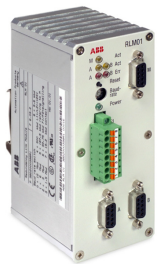
ABBDevice Management PROFIBUS DP/FMS Redundancy Link Module, RLM01
Section 1 Features/ Application
RLM 01 converts one simple, non-redundant Profibus line into two reciprocally redundant lines A/B. The module works bidirectionally, which means that all three interfaces can receive and transmit data
• Conversion: Line M <=> Lines A/B
• Use on PROFIBUS DP/FMS lines
• Automatic line selection
• Transmission rate 9.6 kBit/s .... 12 MBit/s
• Monitoring of communication
• Repeater functionality
• Redundant power supply
• Status and error display
• Monitoring of the power supply
• Potential-free alarm contact
• Simple assembly on DIN mounting rail
You can position the module directly after a master, before a bus segment with several slaves or before an individual slave. PROFIBUS stations with redundant couplers [K] can be directly connected to the PROFIBUS set redundant by RLM 01. Stations with only one interface can be optionally assigned to the A or B line. Each RLM 01 PROFIBUS interface can serve up to 31 PROFIBUS stations. Using repeaters [R] and media converters [O/E] makes it possible to increase the length of the PROFIBUS lines and the number of stations.
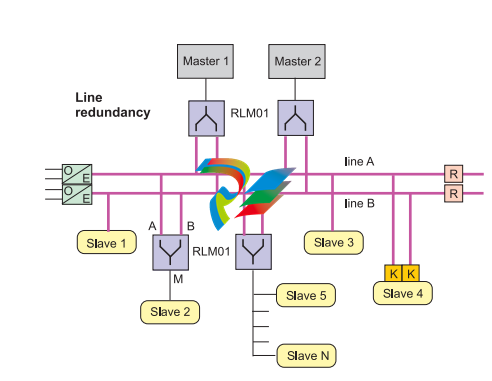
Figure 1. Application example
RLM01 does not support master redundancy where one master only runs line A and the other one only line B. The bus communication is asynchronous, even if both masters balance their program modules against each other on the applicational level. A Melody central unit CMC 60/70 offers clock sy
Network devices like repeater, FOC coupler, DP/PA converter as well as RLM01 cause a N x bit time delay of data telegrams. The delay time (see technical data) is device specific and depends upon the selected baud rate. It must be taken into consideration for the master bus configuration.
Section 2 Description of functions
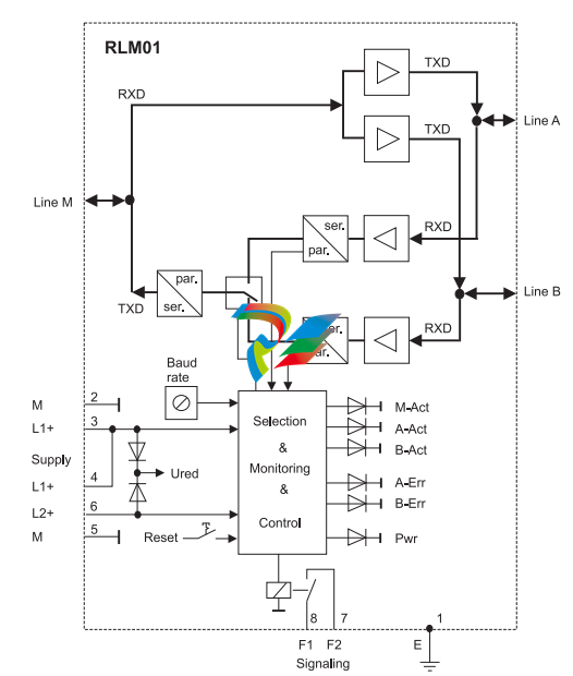
The three RS 485 interfaces of the module support all transmission rates specified in DIN 19245 for the PROFIBUS from 9.6 kBit/s to 12 MBit/s. The module has repeater functionality, i.e., it regenerates the signal shape and the amplitude of received data. RLM 01 monitors all three lines A, B and M for activity and error states. Detected errors are signalled by lit diodes on the front panel. The potentialfree alarm contact activated in parallel to this can be polled for diagnostic purposes by the process control system PCS or by a programmable logic control PLC. The three serial RS 485 interfaces are potential-free relative to each other and to the power supply. This is a functional electrical isolation. The first data coming in over line A or line B with a correct telegram start are routed to terminal M. With simultaneity, either line A or line B is selected at random. Testing and selection is always based on the first character. In the case of a telegram start with error on A, the control logic switches to the redundant line B. The same procedure applies vice-versa for line B. Data coming in over line M with a correct telegram start are routed in parallel to the two terminals A and B. The test for data is always based on the first character. In the case of a telegram start with error, the control logic does not output any data to A and B. Either a single or a redundant power supply with 24 VDC is possible. The distribution of load across L1+ and L2+ is based on the level of the voltages applied. If a voltage source fails, the switch to the redundant supply source is made without interruption. A monitoring logic circuit tests whether both voltages are present.
Section 3 Commissioning
Safety information
To supply RLM 01, use only a safety-low voltage. This requirement also applies to the alarm contact supply. In accordance with the UL/CSA requirements an external protection (e.g. fuse) is prescribed. The fuse rating can amounted to 1.6A to 10A (characteristic: medium slow-acting or slow-acting). Protection of groups of several devices with a common fuse is admissible (several RLM 01 or RLM 01 together with other devices). When selecting a mounting location, make certain that the limit values for ambient conditions specified in the technical data are observed and the module can discharge heat without any obstruction. Do not connect any bus lines that are laid partially or entirely outside buildings. Voltage overload, for example resulting from lightning strikes, may destroy the module. For protection against cases such as these, use optical fibre cable and appropriate medium converters (electrical <==> optical) as high-quality electrical isolation. In accordance with the PROFIBUS installation guideline the shielding of the bus cables are preferably connected at the start and at the end with earth potential. Place the module on a low-resistance and low-inductance earthed DIN mounting rail. Grounding measures by way of the E terminal (1) on the terminal strip are then not required.
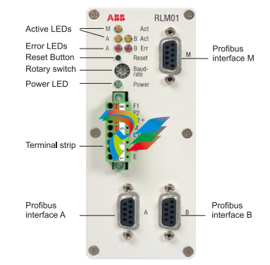
Front panel elements
Three Sub-D connectors A, B and M are located on the front panel of the RLM 01 for connection of the PROFIBUS cable. The 8-pin male multi-pin connector with the associated terminal strip is used to connect the alarm and power supply wires. There are also LEDs for activity/error display, a rotary switch for setting the transmission rate and a reset button (activate transmission rate)
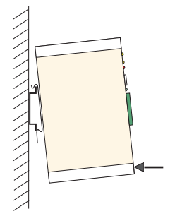
Mounting
The module should preferably be attached vertically on a DIN mounting rail. To do this, place the two rear-side clamps on the top edge of the mounting rail. Then press lightly on the underside of the module until the clamps spread apart and the bottom edge of the rail locks audibly into place. The mounting location should be selected so that the RLM 01 can discharge heat arising from power loss without hindrance. A
distance of > 30 mm should be maintained between the top/bottom of the module and cable ducts, other devices, etc.
Installation
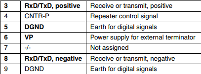
The redundant PROFIBUS lines are connected to the two terminals A and B. Terminal M is provided for the non-redundant PROFIBUS line. All three PROFIBUS connections A, B and M are designed uniformly with 9-pin Sub-D connectors (sockets). The pin assignment conforms to the PROFIBUS standard. RLM 01 uses only pins 3+8 for data transfer and 6+5 for power supply to an external resistor combination for bus termination. The following table shows the maximum assignment for PROFIBUS usage

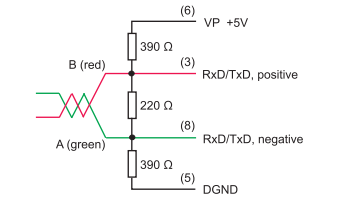
If terminals A/B of RLM 01 are positioned at the beginning or end of a bus segment, two terminals must be provided with one bus termination each (resistor combination). The same also applies for terminal M if it is located at the beginning or the end of a PROFIBUS segment. It is preferable to use PROFIBUS terminals with an integrated resistor combination that can be turned on and off. A shortcircuit-proof power supply to supply the resistors located in the connector is available on pins 5 (VP+) and 6 (DGND). The designation A/B in the following figure refers to the cables in the PROFIBUS cable and not to the redundant PROFIBUS cables, which are also named A/B.
Use only shielded PROFIBUS connectors of suitable design. The connectors should preferably have a cable connection that is angled down at 35° and is no wider than 18 mm.
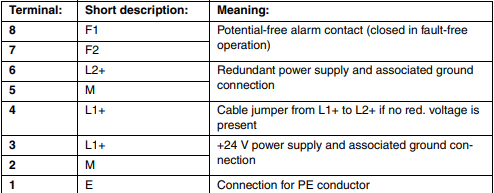
The power supply and alarm lines are connected directly to the terminals labelled 1 to 8. If it is necessary to replace the module, you need only remove the terminal strips. The maximum of 8 cables remain connected. The functions of terminals 1... 8 are given in the following table.
You can press down the orange-coloured pin using a narrow screwdriver to open the cage tension spring. Only press the pin in far enough to feel a noticiable resistance ( about 1 mm below the upper surface of the terminal strip ). Now insert the stripped wire as far as it will go into the large hole on the left. Reliable contact is only ensured if the cage tension spring grasps the wire and not the insulation around it. The cage tension spring can receive solid wires or rough wire strands with cross sections from 0.14 to 1.5 mm2. Please use flexible or rough wire strands with the lowest possible cross section for better handling and reduced mechanical stress to the terminal strip.
Setting the baud rate
Configuration of the RLM 01 merely involves setting the baud rate. It should be set with the rotary switch on the front panel before turning on the power supply. You can select baud rates of from 9.6 kbd to 12 Mbd. If the baud rate is changed during ongoing operation, you should push the reset button once briefly to reset the control logic and the counters etc. to a defined initial state.
Application on ships and maritime systems
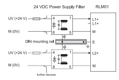
RLM01 is certified for applications on ships and maritime systems by the Germanic Lloyd (GL). To meet the increased requirements regarding EMC and overvoltage, RLM01 must have one or two "24 VDC power supply filters (surge)" depending on the supply (single / redundant). The supply of several RLM01 behind one filter is not admissible. The max. length of the lines between filter and RLM01 must not exceed 1 m. Possibly needed fuse elements have to be arranged before the filter. The electrical connection to ground potential is effected via the module attachment as with RLM01. The following example shows the interconnection in case of a redundant supply of RLM01. For a single supply of RLM01, the L2+ terminal has to be bridged with the second L1+ terminal.
Section 4 Monitoring
The LEDs assigned to lines A, B and M on the front panel are used to indicate bus activity (Act) and possible errors (Err) on the PROFIBUS lines. The monitoring logic in RLM 01 assumes that lines A & B are used for communication during operation. If it is subsequently possible to receive data over only one of the two lines, the non-available line is reported as faulty. If the redundant (second) line also fails, the same state results for the monitoring logic as for a redundant PROFIBUS link A AND B that is not in operation at all. Since the logic has no criterion for making a distinction, no error message is generated by RLM 01. The alarm contact remains closed and the two Act and Err LEDs are unlit. But the condition just described does not go undetected. In this case the PROFIBUS master generates the error message, since it cannot access the slaves either via line A or line B. An Err LED flashing at an undefined pulse/pause ratio indicates that the line in question has failed AND that there is only sporadic data traffic on the redundant line. The monitoring logic can only indicate operating and error states correctly if the baud rate is set correctly. RLM 01 also tests whether the supply voltage is present at inputs L1+ and L2+. A single power supply with L1+ alone always requires a cable jumper from L1+ to L2+ (see Chapter 3). This prevents an unwanted error message
Section 5 Signalling
The monitoring logic in RLM 01 indicates operating and possible error states via LEDs on the front panel. In normal operation, all yellow Act LEDs (flashing or continuous) and the green Pwr LED are lit. The two red Err LEDs are unlit. Any signalling configuration other than this indicates a communication or power supply error
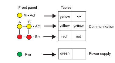
The text (yellow, red, green) in the two following tables means that the corresponding LED is lit, thus displaying an operating or error state
-
 OMRON 3G3XV-A2007 3G3XV-A2007-NEV2
 -
 Omron NJ1019000 NJ1 programable logic controller
 -
 OMRON C120-LK202-EV1/C120LK202EV1
 -
 OMRON C200H-AD003 PLC
 -
 OMRON C200H-CPU23-E COIL 24VDC PLC
 -
 Omron C200HG - C200H-ID212- C200H-OC226 C200HW-BC101 PLC Base Unit
 -
 OMRON C200H-OC222(Output Unit),C200H-PS211(Power Supply Unit),SP001 Module Rack
 -
 OMRON C200H-RT201 PROGRAMMABLE CONTROLLER
 -
 OMRON C200HS-CPU01-E SYSMAC PROGRAMMABLE CONTROLLER
 -
 OMRON C200H-SNT31 C200H Programmable Controllers
 -
 OMRON C200HW-MC402-E Motion control unit
 -
 OMRON C200PC-ISA02-DRM-E PLC ISA bus compatible board card
 -
 OMRON C500-CT012 PLC
 -
 OMRON C500-NC103-E PLC
 -
 OMRON C500-NC222-E PLC
 -
 OMRON C500-PRW05-V1 PLC
 -
 OMRON C500-PRW06 PROGRAMMABLE CONTROLLER
 -
 OMRON C500-PS223-E 3G2A5-PS223-E PLC SYSMAC PROGRAMMABLE CONTROLLER
 -
 OMRON C500-TU001 3G2A5-TU001 PLC PLC
 -
 OMRON C60H-C1DR-DE-V1 Programmable Controllers
 -
 OMRON C60H-C5DR-DE-V1 Programmable Controllers
 -
 OMRON C60H-C6DR-DE-V1 Programmable Controllers
 -
 OMRON CJ1G-CPU44H CPU module
 -
 OMRON CJ1G-CPU45H PLC
 -
 OMRON CJ1M-CPU13-ETN V4.0 PLC PLC
 -
 OMRON CJ1W-AD041-V1 Analog input uni
 -
 OMRON CJ1W-CORT21 PLC module
 -
 OMRON CJ1W-IDP01 Input unit
 -
 OMRON CJ1W-MCH71 - MECHATROLINK-II
 -
 OMRON CJ1W-MD261 Digital I/O
 -
 OMRON CJ1W-NC413 Position control unit
 -
 OMRON CJ1W-NCF71 Position Control Units
 -
 OMRON CJ1W-PTS51 Process Simulation I/O Module
 -
 OMRON CJ1W-PTS52 Process Simulation I/O Module
 -
 OMRON CJ1W-SCU21-V1 PLC
 -
 Omron CJ1W-SCU22 Serial Communication Unit
 -
 OMRON CJ1W-TC001 CJ Series Temperature Control Unit
 -
 Omron CK3W-AX1515N Motion Controller
 -
 Omron CP1E-N60DR-D Compact PLC CPU
 -
 OMRON CP1E-NA20DT1-D PLC PLC
 -
 OMRON CP1H-X40DT-D plc PLC
 -
 OMRON CPM2C-S110C-DRT Interface module
 -
 OMRON CQM1-AD041 PLC
 -
 SAACKE F‑GDSA‑1 / F‑GDSA‑2 Feuerungsautomaten
 -
 SAACKE F-GDSA 143303 Controller SHIPS UPS
 -
 ICS Triplex T8270 Trusted 24 Vdc FanAssembly
 -
 SCHNEIDER M522220000 SA SM_DO16R 16 DIGITAL OUTPUTS MODULE
 -
 LENZ EPL10200-W EPZ-10203 CANPT010W3E
 -
 OMRON CQM1H-ADB21 PLC
 -
OMRON CQM1H-CPU61 PLC
-
 OMRON CQM1H-MAB42 PLC
 -
 OMRON CQM1-TC102 CQM1-TC101 PLC
 -
 OMRON CS1G-CPU44-EV1 PLC
 -
 OMRON CS1G-CPU44H CPU
 -
OMRON CS1H-CPU63-EV1 PLC
-
 OMRON CS1H-CPU66-V1 PLC
 -
 OMRON CS1W-CLK13 PLC communication module
 -
OMRON CS1W-EIP21 PLC
-
 OMRON CS1W-MAD44 PLC PLC
 -
 OMRON CS1W-SCU31-V1 CVM1-BC103 PLC
 -
 Omron CVM1-CPU21-V2 CPU Unit
 -
 OMRON F150-C10E-2 Vision Controller
 -
 OMRON F150-C15E-3 Vision Controller
 -
 OMRON F160-C15E VISION MATE CONTROLLER
 -
 OMRON F500-C10-ETN F500-C15-ETN Vision Sensor
 -
 OMRON F500-VS F500-S1
 -
 OMRON FH-3050 FH Vision Controller
 -
 Omron FQ2-S25050F PLC Smart Camera
 -
 Omron FQM1-MMA22 Motion Module
 -
 OMRON GRT1-TS2P Temperature Module
 -
 OMRON H8PR-24 Cam Positioner
 -
 OMRON IDSC-C1DR-A-E Controller
 -
 OMRON K3HB-HTA-DRT1 Temperature Panel Meter
 -
 Omron KM-N1-FLK Power Detector
 -
 OMRON CJ1G-CPU43H CPU
 -
 OMRON NA5-7W001S-V1 NA5-9W001B-V1 NA5-12W101B-V1 Graphic panel
 -
 OMRON NA5-9W001B-V1 Graphic panel
 -
 OMRON NB10W-TW01B INTERACTIVE DISPLAY
 -
 OMRON NB7W-TW01B +CP1L-EL20DR-D Complete Power Panel
 -
 OMRON NB7W-TX01B INTERACTIVE DISPLAY PLC
 -
 Omron NE1A-SCPU02 Network Controller
 -
 OMRON NA5-7W001B-V1 NA5-7W001S-V1 NA5-9W001B-V1 NA5-12W101B-V1 touch screen
 -
 Omron NS5-SQ00B-V2 NS5-SQ00-V2 NS5-SQ01-V2 NS5-SQ01B-V2 touch display panel
 -
 Omron NJ301-1100 Programmable Logic Controller
 -
 OMRON NJ501-1300 CUP Unit Programmable Controller
 -
 Omron NS12-TS01B-V2 Interactive Display
 -
 OMRON NSJW-ETN21 ETHERNET HMI
 -
 OMRON NT10S-SF121 PLC
 -
 OMRON NT20S-ST121-EV3 Touch Screen
 -
 Omron NX1P2-1140DT-BA Programmable Controller
 -
 OMRON 3G3MV-P10CDT3-E RS422/485 INVERTER BOARD
 -
 Omron C500-ID219 3G2A5-ID219 System Microprocessor
 -
 Omron PLC B7AM-8B16
 -
 OMRON PLC Module CJ1W-AD081-V1
 -
 OMRON R88D-HS10 PLC
 -
OMRON R88D-HT10 plc
-
 OMRON R88D-KN01H-ML2 Servos G5-series
 -
 OMRON R88M-H10030-B plc
 -
 OMRON R88S-H306G plc PLC
 -
 Omron Relay G9SX-GS226-T15-RT
 -
 Omron S8AS-24006N S8AS Smart Power Supply FNIP
 -
 Omron Safety Input Unit NX-SIH400
 -
 OMRON SYSMAC SCY-P1 Sequential Controller
 -
OMRON SYSMAC SCY-P0 13E Sequential Controller
-
 OMRON NS8-TV00B-V2 NS8-TV00-V2 NS8-TV00B-ECV2 NS8-TV00-ECV2 touch display Panel
 -
 Omron V680-CA5D02-V2 Programmable Controller
 -
 OMRON SGDH-04AE-OY Servo Drive
 -
OMRON SGDH-10DE-OY Servo Drive
-
 OMRON SGDS-02A12A PLC + SGMAS-C2ACA21
 -
 OMRON SGMPH-04AAA61D-OY Servo Motor
 -
 Omron ZFV-CA40 Smart Sensor Amp Unit 24VDC 0.8A
 -
OMRON ZFV-NX1 CFP0260 ZFV-A20 VISION CONTROL PANEL
-
 OMRON ZFX-C15 SMART SENSOR AMP UNIT, Vision Sensor LCD
 -
 OMRON ZFX-C20/25-CD SMART SENSOR AMP UNIT, Vision Sensor LCD
 -
 OMRON-DIGITAL TEMPERATURE CONTROLLER E5AC-CX4A5M-014 r
 -
 ABB PFVL141V-2.0MN is an industrial-grade, rectangular roll force load cell
 -
 ABB PFVL141V-1.6MN is an industrial-grade, rectangular roll force load cell
 -
ABB PFVL141V-1.25MN high-performance, rectangular roll force load cell
-
 ABB PFVL141V-1.0MN high-precision, heavy-duty rectangular load cell
 -
 ABB PFVL141V-0.8MN high-precision, heavy-duty rectangular load cell
 -
 ABB PFVL141V-0.63MN high-precision, heavy-duty rectangular load cell
 -
 GE 151X1202YE08PP08 Panel of the case / Structural component
 -
 GE 151X1212HB01MG02 Integrated LCI Controller (Old Model)
 -
 GE 151X1212GC01PC02 LCI Static Startup Controller
 -
 GE 151X1235FD01PK01 High-speed Digital Input Interface Board
 -
 GE 151X1215DK01PC01 Signal Processing / Amplification Board
 -
 GE 151X1238WP99BK01 6-pulse LCI power conversion module
 -
 GE 151X1225DF01PC03RA - Power Conversion / Drive Regulation Board


