
MMS System Manual MMS 6000 Part 2 Direction for use Shaft Vibration Monitor MMS 6110
Three different levels permit definition of the access authorization for operation, configuration and for installation and test of the monitor.
• Access authorization "Factory" includes all adjustments and is intended for installation
purposes by the epro staff.
• Access authorization "Service" is intended for specialists who specifies and configures the
monitor for the actual application.
• Access authorization „Operation“ permits changing settings required for the normal operation.
By means of laptop/PC and the operating kit, the parameters of the selected monitor and the
measuring results (including order analysis, FFT etc.) as well as the status of the monitor can
be watched on the computer screen.
The Operating Kit also contains two measuring cables for measuring the sensor signals at
the mini coax sockets on the monitor front. By means of these cables the coaxial sockets for
the sensor signals 1 and 2 can be connected to an oscilloscope.
An RS 485 interface (at the device connector) serves the connection of the monitor to the
epro MMS 6850 Analysis and Diagnosis system for acquiring and analysing measuring data.
The monitor is designed as printed board in the standard euro format (100 mm of x 60 mm)
with 6 TE width (approx. 30 mm) and an eloxadized front plate.
The supply of the monitor requires +24 V, two supply inputs, decoupled via diodes, permit
redundant supply of the monitor.
CONFIGURATION, MENU FILE
This chapter describes the configuration especially of the MMS 6110 module by using the
MMS 6000W configuration program. The installation software for the configuration program
MMS 6910 W and the MMS 6000 system manual are part of the MMS 6910 Operating kit
and stored on a CD-ROM. The description of the handling of the configuration software and
descriptions of the parameters common to all of the MMS 6000 monitors, are described in
part 1 - CONFIGURATION AND VISUALIZATION - of the MMS 6000 W System manual.
There are two different ways how to configure a new monitor:
1. Select menu "New" in main menu "File", select parameters monitor type and operation mode and set all relevant parameters in menu "Edit".
2. Call up menu "PreDefined" in menu "File" and select a monitor with an operating
mode which definitions suits best to the application. At least channel names must be entered and parameters can then be corrected in menu Edit.
Monitor Configuration New
Menupoint File > New opens dialog window Set up MMS-6000 Monitorconfiguration.
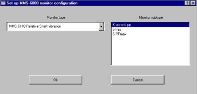
The left part of the menu shows a list where the monitor to be configured is selected. The
right part of the menu shows a list with all operating modes possible for this monitor, one of
them must be chosen with a mouse click.
Possible modes for the MMS 6110:
S0P and SPP Dual channel mode with two separate channels. The configuration
(measurement range, sensor type, limit value etc.) can be selected for
each of the channels, each channel calculates its own characteristical
value (peak-peak or zero-peak value) and checks it on limit exceedings
and faults of the measuring chain.
Smax The resulting maximum value of the shaft vibration for the measuring directions X and Y is calculated according to DIN 45670 characteristical
value A by geometrical addition of the actual values S1 (channel 1) and
S2 (channel 2) [S )t( 1s )t( s2 )t(
2 2
m = + ]. The maximum value Smax is output as characteristical value and checked on limit exceedings.
SPPmax Calculation and output of the greater vibration amplitude Sppmax according to DIN 45670, characteristical value B or max (x, y) according to API
670. The characteristical value, output and checked on limit exceedings,
is formed by the greatest of the two measuring values of channels 1 or 2
in X and Y-measuring direction.
Having confirmed the choice by clicking the OK- button, the program returns to the main
menu. The newly defined monitor must then be configured in menu "File > Edit".
2.2 Monitor type PreDefined
Menu point File > PreDefined opens dialog window PreDefined MMS 6000 Monitor Types.
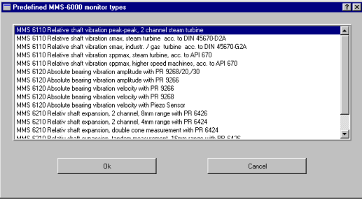
This window shows predefined configurations for different monitor types and their operating
modes for various applications. After selection of the monitor type and confirmation by clicking the OK button, the configuration is stored in the memory.
In any case the device parameters must be adapted to the actual application in menu
File > Edit and the channel designations entered.
Edit monitor configuration
Menu point Edit opens a dialog window with several property pages for setting device parameters.
Property page Administration
In property page Administration the general data, valid for the actual monitor type are
shown.
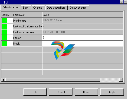
Display field Monitor type
This field shows the predefined monitor type (indicated parameters in this menu cannot be
-
 HIRSCHMANN MSM20-M2M2M2M2SY9HH9E Ethernet media modul
 -
 HIRSCHMANN SPIDER-PL-20-05T1999999TWVHHHH Industrial Ethernet Rail Switch
 -
 Hirschmann SPIDER-PL-20-07T1M2M299TWVHHHH Industrial ETHERNET Rail Switch
 -
.png) Hirschmann (Belden) RS20-1600M2M2SDAEHC09.1.00 DIN-rail managed industrial Fast Ethernet switch
Hirschmann (Belden) RS20-1600M2M2SDAEHC09.1.00 DIN-rail managed industrial Fast Ethernet switch -
 Hirschmann (Belden) RS30-1602O6O6TDAPHC09.1.00 DIN-rail managed industrial Ethernet switch
 -
 Hirschmann (Belden) RS30-2402O6T1SDAPHH09.0.13 DIN-rail industrial Ethernet switch
 -
Hirschmann (Belden) SPIDER-PL-20-04T1S29999TY9HHHH Ethernet DIN-rail switch
-
 HIRSCHMANN RS20-1600T1T1SDAUHX Switch
 -
 HIRSCHMANN BRS42-0012OOOO-SPCZ99HHSES industrial switch
 -
 Hirschmann RS20-0800S2S2TDHPHH09.0.14 Fast Ethernet DIN rail switch.
 -
 HIRSCHMANN MM20-Z6Z6M2M2SAHH Hybrid Fast Ethernet Media Module
 -
 HIRSCHMANN MM20-Z6Z6T1T1SAHH hot-swappable hybrid Fast Ethernet Media Module
 -
 HIRSCHMANN MM20-P9P9T1T1SAHH Hybrid Fast Ethernet Media Module
 -
 HIRSCHMANN MM20-M4T1T1T1SAHH Hybrid Fast Ethernet Media Module
 -
 HIRSCHMANN MM20-M4M4T1T1SAHH Hybrid Fast Ethernet Media Module
 -
 HIRSCHMANN MM20-M2M2M2M2SZHH Ethernet media module
 -
HIRSCHMANN MM20-M2M2M2M2SAHH Ethernet media module
-
 HIRSCHMANN MM20-T1T1T1T1EBH 4-port Fast Ethernet Copper Cable Media Module
 -
HIRSCHMANN MM20-T1T1T1T1SAHH 4-port Fast Ethernet Copper Cable Media Module
-
HIRSCHMANN MM20-T1T1T1T1SAHH 4-port Fast Ethernet Copper Cable Media Module
-
 HIRSCHMANN MM20-Z6Z6EBH Hot-swappable fast Ethernet media module
 -
 HIRSCHMANN MM20-Z6Z6SAHH Ethernet media module
 -
HIRSCHMANN MM20-Z6Z6Z6Z6EBH Industrial Media Module
-
 MSM40-T1T1T1TZ9HH9E99.9.99 HIRSCHMANN Switch
 -
 HIRSCHMANN MS20-0800SAAEHC / MS20-0800SAAEHC0 8-port modular Layer 2 management Ethernet switch
 -
 Hirschmann RSPM20-4T14T1SZ9HHS9 Switch RSPM20-4T14T1SZ9HHS9
 -
 HIRSCHMANN RS20-1600M2M2SDAEHH09.1. RS20/30/40 Managed Switch configurator
 -
HIRSCHMANN RS20-1600M2M2SDAEHX09.0.00 Ethernet switch
-
 HIRSCHMANN BELDEN SPIDER-PL-20-07T1M2M299TY9HHHH / SPIDERPL2007T1M2M299TY9HHHH
 -
HIRSCHMANN MM3-1FXS2/3TX1 Switching Board Module
-
 HIRSCHMANN RSPE30-24044O7T99-ECCP999HHSE2A08.1.00 Industrial-grade fanless management-type Ethernet switch
 -
 HIRSCHMANN RS30-1602OOZZSDAEHC09.1.00 DIN-rail-mounted managed Layer 2 Ethernet switch
 -
 HIRSCHMANN MACH104-20TX-F Managed 24-port Full Gigabit 19" Switch
 -
 HIRSCHMANN Switch RS20-0800M4M4SDAE
 -
Hirschmann RS30-1602O6O6SDAEHH09.1. Management-type Ethernet switch
-
 Hirschmann RS30-1602OOZZSDAEHC09.0.10 Open rack-style Ethernet switch
 -
 HIRSCHMANN RSPE30-24044O7T99-SCCV999HHSI2SXX.X.XX High-Availability Seamless Redundancy
 -
HIRSCHMANN RSPE30-24044O7T99-SCCZ999HHSE2A DIN-rail Ethernet switch
-
HIRSCHMANN MM2-4TX1-EEC switch
-
HIRSCHMANN MSM40-T1T1T1T1TZ9HH9E99.9.99 Module
-
 HIRSCHMANN RS20 Rail Switch RS20-0400S4T1SDAEHC07.1.01
 -
 HIRSCHMANN M4-FAST8-SFP Fast Ethernet media module
 -
 HIRSCHMANN RS20-0400M2T1SDAP Managed Fast-Ethernet-Switch
 -
 HIRSCHMANN BELDEN SPIDER II 8TX/1FX EEC Industrial Ethernet Rail Switch
 -
HIRSCHMANN MM3-2FXS2/2TX1
-
 HIRSCHMANN RS2-4TX/1FX EEC Industrial Ethernet Rail Switch
 -
 RS30-0802O6O6SDAEHC09.0.10 HIRSCHMANN Switch
 -
 HIRSCHMANN m4-8TP-RJ45 Ethernet Media Module
 -
 HIRSCHMANN MSP30-24040SCZ9URHHE3A switch
 -
 Hirschmann rack MS30-1602SAAPHC
 -
 HIRSCHMANN RS2-FX/FX Industrial Switch Module
 -
Rs1txfx - Hirschmann - Rs1-Tx/Fx Rail Switch
-
RS20-0800S2S2SDAEHC09.1.00 HIRSCHMANN Commutator
-
 Hirschmann EAGLE20 TX/TX Industrial Security Router
 -
 Hirschmann SPIDER-SL-20-04T1S29999SY9HHHH Industrial Switch
 -
 HIRSCHMANN MAR1040-4C4C4C4C9999SMMHRHHXX.X. Gigabit Ethernet Switch configurator
 -
 Hirschmann MAR1040 Industrial Switch
 -
 HIRSCHMANN BELDEN RS30-1602O6O6SDAE
 -
Hirschmann RS20-1600M2M2SDAUHC Ethernet DIN rail switch
-
 HIRSCHMANN OCTOPUS 24M industrial switch
 -
 HIRSCHMANN RS20-1600T1T1SDAE Management-type Ethernet switch
 -
 HIRSCHMANN RS20-1600T1T1SDAUHH industrial switch
 -
HIRSCHMANN RS20-0800M2M2SDAPHC09.0.04 switch
-
 Hirschmann MR 8-03 24V DC Industrial Modular Bridge/Router
 -
 HIRSCHMANN RS20-0400M2T1SDAPHC08.0.01 Managed Switch
 -
 MACH1130 Hirschmann Industrial Switch
 -
 HIRSCHMANN 943824-002 SPIDER 5TX Industrial Ethernet Switch
 -
 HIRSCHMANN RS30-0802O6O6SDAEHC09.1.00 Managed Industrial Switch
 -
 HIRSCHMANN RS20-0400M2M2TDAEHC04.0.01 Industrial Switch
 -
 HIRSCHMANN BRS20-0600Z6Z6-STCZ99HHSES Industrial Switch
 -
 HIRSCHMANN MACH104-20TX-FR-L3P Industrial Ethernet Switch
 -
 HIRSCHMANN RS40-0009CCCCEDBPHH06.0.01 Industrial Switch
 -
 HIRSCHMANN RS2-3TX/2FX EEC Industrial Ethernet Switch
 -
 Hirschmann MACH 1020/1030 Fast/Gigabit Rack Mount Switches
 -
HIRSCHMANN RS20-0800M2M2SDAPHC09.0.14 Industrial Switch
-
 HIRSCHMANN RS20-1600T1T1SDAEHC09.0.04 Industrial Switch
 -
 HIRSCHMANN RSB20-0800T1T1EAABHH Industrial Switch
 -
 HIRSCHMANN MACH4002-48+4G-L3E Industrial Backbone Switch
 -
 HIRSCHMANN RS20-0400S2T1SDAE Industrial Managed Switch
 -
HIRSCHMANN RS20-0800S2T1SDAUHC Industrial Switch
-
 HIRSCHMANN RS20-2400S4S4SDAEHC09.0.14 industrial switch
 -
 HIRSCHMANN OS20-001200T5T5T5- TBBZ999HHNE3S 08.1.00 industrial switch
 -
HIRSCHMANN OS20-001200T5T5T5- TBBZ999HHNE3S 08.1.00 industrial switch
-
 HIRSCHMANN RS40-0009CCCCSDAEHH09.0.14 switch
 -
 Hirschmann RS20-1600T1T1SDAUHC Management-type Ethernet Switch
 -
 Hirschmann M1-8SFP Switche
 -
Hirschmann Industrial Ethernet Ruggedized Switch MACH1000 Family
-
 Basler Electric, Solid State Protective Relay, BE1-60
 -
BASLER ELECTRIC SR4A-2B15B3A Static Voltage Regulator
-
.png) BASLER ELECTRIC EXCITER DIODE MONITOR EDM-200
BASLER ELECTRIC EXCITER DIODE MONITOR EDM-200 -
.png) BASLER ELECTRIC DECS125-15-B2C5 DIGITAL EXCITATION CONTROL SYSTEM V 2.0.9
BASLER ELECTRIC DECS125-15-B2C5 DIGITAL EXCITATION CONTROL SYSTEM V 2.0.9 -
 BASLER ELECTRIC BE1-851 OVERCURRENT PROTECTION RELAY MECHANISM
 -
 Basler Electric BE1-51A / BE151A
 -
 Basler Electric BE1-40Q Loss of Excitation Relay
 -
 Basler Electric BE1-87G Variable Percentage Differential Relay
 -
 Basler Electric BE1-11 Protection System I5A3M2P2N0EA00
 -
 BASLER ELECTRIC DECS-200-1C Digital Excitation Control System
 -
 Basler Electric / Kohler BE1-11g Generator Protection Relay G5A3M2J2N0E000
 -
BASLER ELECTRIC DECS125-15 DIGITAL EXCITATION CONTROL SYSTEM
-
 BASLER ELECTRIC BE1-951 OverCurrent Protecton System
 -
Basler Electric DECS-200-1L Digital Excitation Control System
-
 Basler Electric DGC-2020HD-5NS1DNSBA Digital Genset Controller -
 -
 BASLER ELECTRIC BE1-81T1EE1WA0N1F / BE181T1EE1WA0N1F
 -
 BASLER ELECTRIC BE1-25M1EA6PN5R1F / BE125M1EA6PN5R1F
 -
 BASLER ELECTRIC DECS-250-LN1SN1N DIGITAL EXCITATION CONTROL SYSTEM
 -
Basler Electric DECS-250-CN2CN 1N Digital Excitation Control System Unit
-
 BASLER ELECTRIC DECS-300-C0N0 DIGITAL EXCITATION CONTROL SYSTEM
 -
 BASLER ELECTRIC BE1-87T-A1E-A1J-D0S1F / BE187TA1EA1JD0S1F
 -
BASLER ELECTRIC BE1-11-G6D1M0J2P0E000 Protection System
-
 BASLER ELECTRIC BE1-GPS100-E4N1H1N GENERATOR PROTECTION SYSTEM
 -
 Jaquet Relay card (Auxiliary module) FTV 3090 377Z-03985
 -
 Jaquet Trip Chain Control card FTBU 3034 377Z-05030
 -
 Jaquet with input card -E04 FTFU 3024 -E04 377Z-05855
 -
 Jaquet with input card -E03 FTFU 3024- E03 377Z-03983
 -
 Jaquet FTFU 3024- E02 377Z-03982 with input card -E02
 -
 Jaquet FTFU 3024-E01 377Z-03981 with input card -E01
 -
 Hirschmann RS20-2400T1T1SDAE Industrial Managed Ethernet Switch
 -
 Hirschmann BELDEN EAGLE30-04022O6TT999SCCV9HSE3F
 -
 Hirschmann MM3-2FXS2/2TX MICE Media Module
 -
 Hirschmann RS20-1600M2M2SDAPHC08.0.05 Industrial Managed Switch
 -
 Hirschmann OZD Profi 12M G12-1300 PRO Fieldbus Repeater
 -
Hirschmann SPIDER 4TX/1FX-ST EEC Industrial Ethernet Switch
-
 Hirschmann MM2-2FXM3/2TX1 MICE Media Module
 -
 Hirschmann RS20-2400M2M2SDAPHC09.0.14 Industrial Switch
 -
 Hirschmann RS20-0400M2M2SDAEHC07.1.05 OpenRail Switch
 -
 Hirschmann OZD Profi 12M G12-EEC Fieldbus Repeater
 -
HIRSCHMANN MDA422-1/2-3.5c-23/46 sensor
-
Hirschmann RS30-2402T1T1SDAUHC Managed Industrial Switch


