
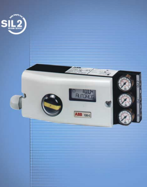
ABBElectro-Pneumatic Positioner TZIDC
Low operating cost
Compact design
Well-proven technology
Robust and environmentally ruggedized
Wide operating temperature range
-40 ... 85 °C (-40 ... 185 °F)
Easy to commission, “single pushbutton”
operating philosophy
Mechanical position indicator
ATEX, FM, CSA, GOST and IECEx approvals
For SIL2 safety loops
1 Description Pos: 3.2 /==== Wechsel ein- auf zweispaltig ==== @ 0mod_1130421847171_3101.doc @ 3828
Wechsel ein-auf zweispaltig Pos: 3.3 /Technische Daten / Datenblatt/Aktorik/Stellungsregler/Allgemein/Kurzbeschreibung/Kurzbeschreibung @ 10mod_1173180169769_3101.doc @ 71118
The TZIDC is an electronically configurable positioner with
communication capabilities designed for mounting to pneumatic
linear or rotary actuators. It features a small and compact design, a
modular construction, and an excellent cost-performance ratio.
Fully automatic determination of the control parameters and
adaptation to the final control element yield considerable time savings
and an optimal control behavior.
Pos: 3.4 /Überschriften/1.1/2-spaltig/Pneumatik @ 10mod_1176211138453_3101.doc @ 76683
1.1 Pneumatics Pos: 3.5 /Technische Daten / Datenblatt/Aktorik/Stellungsregler/Allgemein/Kurzbeschreibung/Pneumatik @ 10mod_1173180645393_3101.doc @ 71139 a
An I/P module with subsequent pneumatic amplifier is used to control
the pneumatic actuator. The well-proven I/P module proportionally
converts the permanent electrical positioning signal from the CPU
into a pneumatic signal used to adjust a 3/3-way valve.
The air flow for pressurizing or depressurizing the actuator is
continuously adjusted. As a result, excellent control is achieved.
When reaching the set point, the 3/3-way valve is closed in center
position to minimize the air consumption.
Four different pneumatics versions are available: for single-acting or
double-acting actuators, each with “fail-safe” or “fail-freeze” function.
Pos: 3.6 /Überschriften/1.1.1/2-spaltig/Sicherheitsfunktion "entlüftend" @ 10mod_1176211744343_3101.doc @ 76809
1.1.1 “Fail-safe” function
Pos: 3.7 /Technische Daten / Datenblatt/Aktorik/Stellungsregler/Allgemein/Kurzbeschreibung/Sicherheitsfunktion "entlüftend" @ 10mod_1176211673796_3101.doc @ 76788
If the electrical power supply fails, the positioner output 1 is
depressurized, and the pneumatic actuator’s return spring moves the
valve to the defined safe position. In case of a double-acting actuator
the second output 2 is additionally pressurized.
Pos: 3.8 /======= Spaltenumbruch ======== @ 0mod_1132937966324_3101.doc @ 3831
Pos: 3.9 /Überschriften/1.1.1/2-spaltig/Sicherheitsfunktion "blockierend" @ 10mod_1176211798765_3101.doc @ 76830
1.1.2 “Fail-freeze” function
Pos: 3.10 /Technische Daten / Datenblatt/Aktorik/Stellungsregler/Allgemein/Kurzbeschreibung/Sicherheitsfunktion "blockierend" @ 10mod_1176211845484_3101.doc @ 76851
If the electrical power supply should fail, the positioner output 1 (and
2, if applicable) is closed and the pneumatic actuator stops
(“freezes”) the valve in the current position. If compressed air supply
should fail, the positioner depressurizes the actuator.
Pos: 3.11 /Überschriften/1.1/2-spaltig/Bedienung @ 10mod_1176211172234_3101.doc @ 76704
1.2 Operation Pos: 3.12 /Technische Daten / Datenblatt/Aktorik/Stellungsregler/Allgemein/Kurzbeschreibung/Bedienung (Kommunikationsmöglichkeit) @ 10mod_1173184631054_3101.doc @ 71160
The positioner has a built-in operating panel providing a 2-line LCD
and 4 pushbuttons for optimal local configuration, commissioning and
operational monitoring.
Alternatively, the appropriate configuration program and the available
communication option can be used.
Pos: 3.13 /Überschriften/1.1/2-spaltig/Kommunikation @ 10mod_1176211201546_3101.doc @ 76725
1.3 Communication Pos: 3.14 /Technische Daten / Datenblatt/Aktorik/Stellungsregler/TZIDC / TZIDC-200/Kurzbeschreibung/Kommunikation @ 10mod_1176212225390_3101.doc @ 76893
The standard TZIDC model has a local communication interface (LKS
connector). Additionally, a “HART communication” option for
communication via the 20 mA signal is available. Both
communications are based on the HART Protocol.
Pos: 3.15 /Überschriften/1.1/2-spaltig/Ein-/Ausgänge @ 10mod_1176211233015_3101.doc @ 76746
1.4 Inputs and outputs Pos: 3.16 /Technische Daten / Datenblatt/Aktorik/Stellungsregler/TZIDC / TZIDC-200/Kurzbeschreibung/Ein-/Ausgänge @ 10mod_1176212290390_3101.doc @ 76914
In addition to its input for the analog position set point the TZIDC
positioner is equipped with a digital input which can be used to
activate various protective functions in the device via the process
control system. A digital output allows you to output collective alarms
or fault messages.
Pos: 3.17 /Überschriften/1.1/2-spaltig/Modularer Aufbau @ 10mod_1176211317984_3101.doc @ 76767
1.5 Modular design Pos: 3.18 /Technische Daten / Datenblatt/Aktorik/Stellungsregler/Allgemein/Kurzbeschreibung/ModularerAufbau @ 10mod_1173184783043_3101.doc @ 71181 q
The TZIDC basic model can be enhanced at any time by retrofitting
optional equipment. Option modules for analog or digital position
feedback or a shutdown-module can be installed. Additionally, a
mechanical position indicator, proximity switches or 24 V
microswitches are available for indicating the position independently
of the mother board function
Electro-Pneumatic Positioner TZIDC 10/18-0.22-EN
for 4 … 20 mA two-wire technology
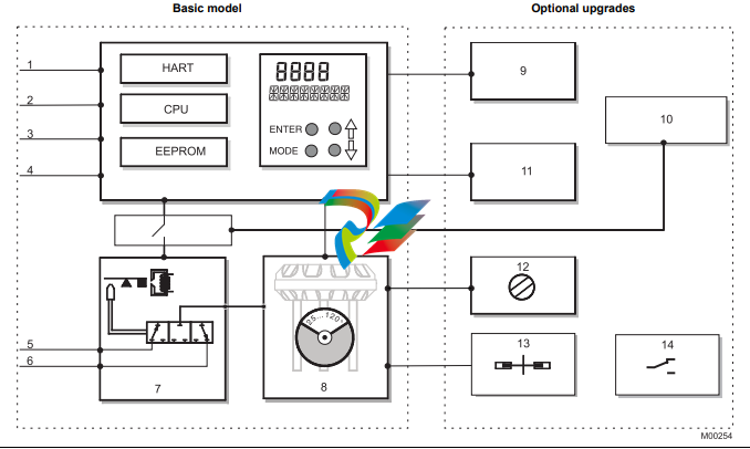
Basic model Optional upgrades
1 LKS plug 9 Plug module for analog feedback (4 … 20 mA)
2 Positioning signal 4 … 20 mA 10 Plug-in module for safety shutdown (forced depressurization)
3 Digital input 11 Plug module for digital feedback
4 Digital output DO 12 Installation kit for mechanical position indicator
5 Supply, 1.4 … 6 bar 13 Installation kit for digital feedback with proximity switches
6 Exhaust 14 Installation kit for digital feedback with 24 V microswitches
7 I/P module with 3/3-way valve
8 Position sensor (optional up to 270° rotation angle)
Important
With optional upgrades either the “Installation kit for digital feedback with proximity switches” (13) or the “Installation
kit for digital feedback with microswitches 24 V” (14) can be used.
In both cases, the “mechanical position indicator” (8) must be installed.
2 Mounting versions Pos: 5.2 /==== Wechsel ein- auf zweispaltig ==== @ 0mod_1130421847171_3101.doc @ 3828
Wechsel ein-auf zweispaltig Pos: 5.3 /Überschriften/1.1/2-spaltig/Genormter Anbau an pneumatische Linearantriebe @ 10mod_1176212852312_3101.doc @ 76956
2.1 To linear actuators in accordance with the
standard Pos: 5.4 /Technische Daten / Datenblatt/Aktorik/Stellungsregler/Allgemein/Montage/Genormter Anbau an pneumatische Linearantriebe @ 10mod_1176213091968_3101.doc @ 77040
Lateral attachment is in accordance with DIN / IEC 534 (lateral
attachment to NAMUR). The required attachment kit is a complete
set of attachment material, but does not include the screwed pipe
connections and air pipes.
Pos: 5.5 /Überschriften/1.1/2-spaltig/Genormter Anbau an pneumatische Schwenkantriebe @ 10mod_1176212899953_3101.doc @ 76977
2.2 To rotary actuators in accordance with the
standard Pos: 5.6 /Technische Daten / Datenblatt/Aktorik/Stellungsregler/Allgemein/Montage/Genormter Anbau an pneumatische Schwenkantriebe @ 10mod_1176213146937_3101.doc @ 77061
This attachment is designed for mounting according to the standard
VDI/VDE 3845. The attachment kit consists of a console with
mounting screws for mounting on a rotary actuator. The adapter for
coupling the positioner feedback shaft to the actuator shaft has to be
ordered separately. Screwed pipe connections and air pipes have to
be provided on site.
Pos: 5.7 /======= Spaltenumbruch ======== @ 0mod_1132937966324_3101.doc @ 3831
Pos: 5.8 /Überschriften/1.1/2-spaltig/Integrierter Anbau an Regelventile @ 10mod_1176212940421_3101.doc @ 76998
2.3 Integral mounting to control valves Pos: 5.9 /Technische Daten / Datenblatt/Aktorik/Stellungsregler/Allgemein/Montage/Integrierter Anbau an Regelventile, TZIDC-1x0 @ 10mod_1176213402234_3101.doc @ 77103
The TZIDC positioner featuring standard pneumatic action is also
suitable for integral mounting.
The required holes are found at the back of the device.
The benefit of this design is that the point for mechanical stroke
measurement is protected and that the positioner and actuator are
linked internally. No external tubing is required.
Pos: 5.10 /Überschriften/1.1/2-spaltig/Besondere antriebsspezifische Anbauversionen @ 10mod_1176212991062_3101.doc @ 77019
2.4 Special actuator-specific mounting Pos: 5.11 /Technische Daten / Datenblatt/Aktorik/Stellungsregler/Allgemein/Montage/Besondere antriebsspezifische Anbauversionen @ 10mod_1173186727709_3101.doc @ 71265
In addition to the mounting methods described above, there are
special actuator-specific attachments.
Please contact us for details.
Electro-Pneumatic Positioner TZIDC 10/18-0.22-EN
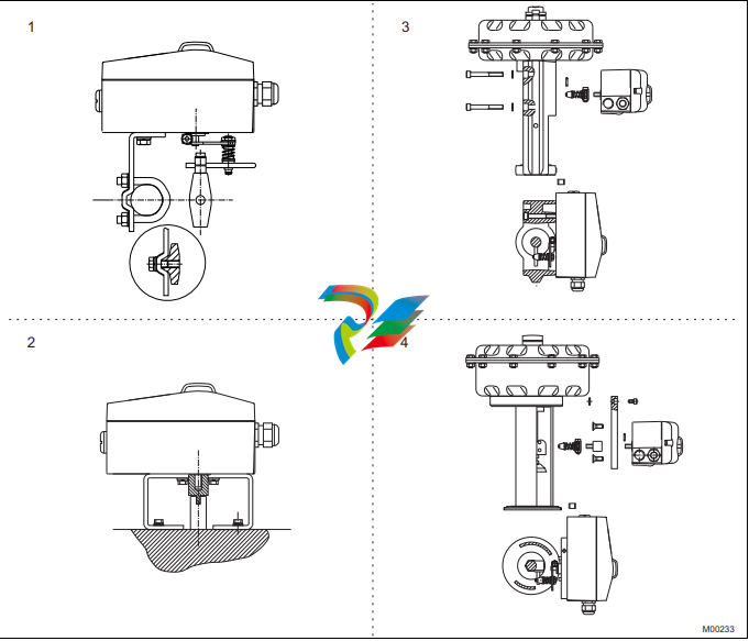
Fig. 2: Mounting options
1 Mounting to linear actuators acc. to DIN / IEC 534 3 Integral mounting to control valves
2 Mounting to rotary actuators to VDI / VDE 3845 4 Integral mounting to control valves by using an adapter panel
3 Operation Pos: 7.2 /==== Wechsel ein- auf zweispaltig ==== @ 0mod_1130421847171_3101.doc @ 3828
Wechsel ein-auf zweispaltig Pos: 7.3 /Überschriften/1.1/2-spaltig/Allgemeines @ 10mod_1176213970765_3101.doc @ 77124 A
3.1 General Pos: 7.4 /Technische Daten / Datenblatt/Aktorik/Stellungsregler/Allgemein/Betrieb/Allgemeines @ 10mod_1176214294328_3101.doc @ 77292
Microprocessor-based position control in the TZIDC provides for
optimal results. The positioner features high-precision control
functions and high operational reliability. Due to their elaborate
structure and easy accessibility, the device parameters can be
quickly adapted to the respective application.
The total range of parameters includes:
- Operating parameters
- Adjustment parameters
- Monitoring parameters
- Diagnosis parameters
- Maintenance parameters
Pos: 7.5 /Überschriften/1.1.1/2-spaltig/Betriebsparameter @ 10mod_1176214001500_3101.doc @ 77145
3.1.1 Operating parameters
Pos: 7.6 /Technische Daten / Datenblatt/Aktorik/Stellungsregler/TZIDC / TZIDC-200/Betrieb/Betriebsparameter @ 10mod_1176214346265_3101.doc @ 77343
The following operating parameters can be set manually if required:
Signal
Signal min. 4 mA, max. signal 20 mA (0 ... 100 %)
freely selectable for split-range operation
min. range 20 % (3.2 mA)
recommended range > 50 % (8.0 mA)
Action (positioning signal)
Increasing: Signal 4 ... 20 mA = position 0 ... 100 %
Increasing: Signal 20 ... 4 mA = position 0 ... 100 %
Characteristic curve (travel = f {signal})
Linear, equal percentage 1:25 or 1:50 or 25:1 or 50:1 or freely
configurable with 20 reference points.
Travel limit
The positioning travel, i.e. the stroke or angle of rotation, can be
reduced as required within the full range of 0 ... 100 %, provided that
a minimum value of 20 % is observed.
Shut-off function
This parameter can be set separately for each end position. When
the respective configured limit value is exceeded, the shut-off
function causes immediate travel of the actuator until reaching the set
end position.
When the shut-off value is set to “0”, the position is further controlled,
even in the respective end position.
Travel time prolongation
This function can be used to increase the max. travel time for full
travel. This time parameter can be set separately for each direction.
Important
This function can only be used with the pneumatics with the
safety function “fail-safe”.
Switching points for the position
This parameter allows you to define two position limits for signaling
(see option “Module for digital position feedback”).
Digital output
The alarms generated in the TZIDC positioner can be polled via the
digital output as a collective alarm.
The desired information can be selected via the operator panel or
remotely via the configuration program.
The output can be set to “active high” or “active low”, as required.
Digital input
For the digital input, one of the following safety options can be
selected. You may use the operator’s panel or configuration program
to select an option.
- No function (default)
- Move to 0 % position
- Move to 100 % position
- Hold previous position
- disable local configuration
- Disable local configuration and operation
- Disable any access (no local or remote access via a PC)
The selected function is activated once the 24 V DC signal is no
longer applied (< 11 V DC).
Pos: 7.7 /Überschriften/1.1.1/2-spaltig/Justageparameter @ 10mod_1176214036515_3101.doc @ 77166
3.1.2 Adjustment parameters
Pos: 7.8 /Technische Daten / Datenblatt/Aktorik/Stellungsregler/TZIDC / TZIDC-200/Betrieb/Justageparameter @ 10mod_1176214397515_3101.doc @ 77364
The TZIDC positioner has a special function for automatic adjustment
of the parameters.
Additionally, the control parameters can be set automatically (in
adaptive control mode) or manually to optimally adapt them to the
process requirements.
Tolerance band
When reaching the tolerance band the position is considered as
corrected. From this point on, the position is further slowly readjusted until the dead band is reached. The factory setting for this
parameter is 0.3 %.
Dead band (sensitivity)
When reaching the dead band, the position is held. The factory
setting for this parameter is 0,1 %.
Actuator spring action
Selection of the sensor shaft rotating sense (looking into the open
case), if the valve is moved to the safe position by the actuator spring
(actuator is depressurized via Y1/OUT1).
For double-acting actuators the actuator spring action corresponds to
pressurizing the pneumatic output (OUT2).
Display 0 ... 100 %
Adjusting the display (0 ... 100 %) according to the direction of action
for opening or closing the valve.
Pos: 7.9 /Überschriften/1.1.1/2-spaltig/Betriebsüberwachungsparameter @ 10mod_1176214071453_3101.doc @ 77187
3.1.3 Monitoring parameters
Pos: 7.10 /Technische Daten / Datenblatt/Aktorik/Stellungsregler/TZIDC / TZIDC-200/Betrieb/Betriebsüberwachungsparameter @ 10mod_1176214447375_3101.doc @ 77385 B
Various functions for permanent operational monitoring are
implemented in the TZIDC operating program. The following states
will be detected and indicated, e.g.:
- 4 ... 20 mA signal out of range
- position out of the adjusted range
- positioning time-out (adjustable time parameter)
- position controller inactive
- counter limits (settable in the diagnosis phase) exceeded
While automatic commissioning is in progress, the current state is
continuously indicated on the integrated LCD.
During operation, the LCD shows the most important process
variables:
- current position (in %),
- malfunctions, alarms, messages (as code)
Access to extended monitoring parameters is possible via HART
communication and the DTM.
3.1.4 Diagnosis parameters
Pos: 7.13 /Technische Daten / Datenblatt/Aktorik/Stellungsregler/Allgemein/Betrieb/Diagnoseparameter @ 10mod_1176214500906_3101.doc @ 77406
The diagnosis parameters of the TZIDC program inform the operator
about the operating conditions of the valve.
From this information the operator can derive which maintenance
works are required, and when.
Additionally, limit values can be defined for these parameters. When
they are exceeded, an alarm is reported.
The following values are e.g. determined:
- Number of movements performed by the valve
- Total travel
The diagnosis parameters and limit values can be called up, set, and
reset via HART communication, using the configuration program.
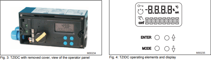
Pos: 7.14 /Überschriften/1.1/2-spaltig/Bedienpanel @ 10mod_1176214143953_3101.doc @ 77229
3.2 Operator panel Pos: 7.15 /Technische Daten / Datenblatt/Aktorik/Stellungsregler/Allgemein/Betrieb/Bedienpanel TZIDC-1x0 @ 10mod_1176214815500_3101.doc @ 77427
The TZIDC positioner’s operator panel with four pushbuttons allows
for
- operational monitoring
- manual control
- configuration
- fully automatic commissioning
The operator panel is protected by a cover which avoids
unauthorized access to the operating elements.
Pos: 7.16 /======= Spaltenumbruch ======== @ 0mod_1132937966324_3101.doc @ 3831
Pos: 7.17 /Überschriften/1.1.1/2-spaltig/Ein-Tasten-Inbetriebnahme @ 10mod_1176214193156_3101.doc @ 77250
3.2.1 Single-button commissioning
Pos: 7.18 /Technische Daten / Datenblatt/Aktorik/Stellungsregler/TZIDC / TZIDC-200/Betrieb/Ein-Tasten-Inbetriebnahme @ 10mod_1176214842843_3101.doc @ 77448
Commissioning the TZIDC positioner is especially easy. The
standard Autoadjust function for automatic adaptation of the device
parameters can be started by simply pressing a single front panel
button, and without knowing parameterization details.
Depending on the selected actuator type (linear or rotary), the
displayed zero position is automatically adapted:
- for linear actuators counter-clockwise (CTCLOCKW)
- for rotary actuators clockwise (CLOCKW).
Besides this standard function, a customized “Autoadjust” function is
available. The function is launched either via the operator’s panel or
HART communication.
Pos: 7.19 /Überschriften/1.1.1/2-spaltig/Anzeigen @ 10mod_1176214259859_3101.doc @ 77271
3.2.2 Display
Pos: 7.20 /Technische Daten / Datenblatt/Aktorik/Stellungsregler/TZIDC / TZIDC-200/Betrieb/Anzeigen @ 10mod_1176214873937_3101.doc @ 77469
The information indicated by the 2-line LC display is permanently
updated and adapted during operation, to inform the operator in an
optimal way.
During control operation (control with or without adaptation) the
following TZIDC data can be called up by pressing the pushbuttons
briefly:
- Up button: Current setpoint (mA)
- Down button: Temperature in device
- Up + Down buttons: Current control deviation
4 Communication Pos: 9.2 /==== Wechsel ein- auf zweispaltig ==== @ 0mod_1130421847171_3101.doc @ 3828
Wechsel ein-auf zweispaltig Pos: 9.3 /Überschriften/1.1/2-spaltig/DTM @ 10mod_1176215310421_3101.doc @ 77511
4.1 DTM Pos: 9.4 /Technische Daten / Datenblatt/Aktorik/Stellungsregler/TZIDC / TZIDC-200/Kommunikation/DTM @ 10mod_1176215507046_3101.doc @ 77595
The DTM (Device Type Manager) for TZIDC is based on the
FDT/DTM technology (FDT 1.2) and can be integrated in a process
control system or loaded in a PC with the DSV401 (SMART VISION)
program. This allows you to work with the same user interface in the
commissioning phase, during operation, and for service tasks for
monitoring the device, setting parameters, and uploading data.
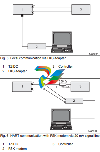
Communication is based on the HART protocol. It occurs via a local
interface connection (LKS) or in frequency-modulated mode using an
FSK-modem connected at any chosen point of the 20 mA signal line.
Communication has no effect on operation. Newly set parameters are
saved in the non-volatile memory directly upon the download into the
device, and become active immediately.
Pos: 9.5 /Überschriften/1.1/2-spaltig/LKS-Adapter (RS-232 Schnittstellenwandler) @ 10mod_1176215338250_3101.doc @ 77532
4.2 LKS adapter (RS-232 interface converter) Pos: 9.6 /Technische Daten / Datenblatt/Aktorik/Stellungsregler/TZIDC / TZIDC-200/Kommunikation/LKS-Adapter (RS-232 Schnittstellenwandler) @ 10mod_1176215612828_3101.doc @ 77616
You can easily connect your TZIDC positioner to a PC, e.g., in the
workshop or in the commissioning phase, by using the positioner’s
LKS adapter (LKS = local communication interface).
An RS-232 interface converter adapts the signals on the serial PC
port to the level of the positioner’s LKS.
Pos: 9.7 /Überschriften/1.1/2-spaltig/FSK-Modem @ 10mod_1176215390421_3101.doc @ 77553
4.3 FSK Modem Pos: 9.8 /Technische Daten / Datenblatt/Aktorik/Stellungsregler/TZIDC / TZIDC-200/Kommunikation/FSK-Modem @ 10mod_1176215656328_3101.doc @ 77637
The FSK modem establishes a digital frequency-modulated
communication (Frequency Shift Keying) with the TZIDC positioner.
Tapping is possible at any chosen point of the 20 mA signal line.
We recommend that you use an electrically isolated FSK modem. It is
bus-compatible when used with isolating amplifiers. Even connecting
explosion-protected field devices is possible, on condition that the
FSK modem is run outside the hazardous area.
-
 Applied Materials (AMAT) 0190-34512 4-Channel DeviceNet Scanner Interface
 -
 Applied Materials (AMAT) 0190-34282 High-Stability Process Control Module
 -
Applied Materials (AMAT) 0190-27707 High-Precision DeviceNet I/O Controller
-
 Applied Materials (AMAT) 0190-27072 High-Performance Semiconductor Interface
 -
 AMAT 0190-24007 CPCI-3720CF Single Board Computer
 -
 AMAT 0190-23905 Spellman ESC High Voltage Power Supply
 -
 AMAT 0190-22967 High-Density Analog I/O Control Board
 -
 AMAT 0190-22543 High-Precision Analog Input/Output Module
 -
 AMAT 0190-17964 Etch DPS Interlock Module
 -
 AMAT 0190-17894 Interlock Module Conductor HART
 -
 AMAT 0190-17081 2U CompactPCI System Host Processor
 -
 AMAT 0190-16926 and 0190-16928 Based on Compact PCI
 -
AMAT 0190-15915 Intelligent I/O Control Module
-
 AMAT 0190-15840 4-Port UPA DeviceNet Interface Module
 -
 AMAT 0190-15384 Advanced Digital Signal Interface Module
 -
 AMAT 0190-14027 Wafer Flat Finder PCB
 -
 AMAT 0190-12695 SBS CL7 3U CompactPCI Single Board Computer
 -
 AMAT 0190-11817 CP3-SER16-TTL 16-Port Serial Interface Card
 -
 AMAT 0190-11524 CDN500-25 Interlock Module
 -
 AMAT 0190-07450 CompactPCI 48-Channel Digital I/O Interface Board
 -
 AMAT 0190-05990-001 Maglev Rotation System Controller (300mm)
 -
 AMAT 0190-05647 LK3710 Serial Module Transition Card
 -
 AMAT 0190-04457 High-Performance Integrated Circuit Control Module
 -
 Applied Materials (AMAT) 0190-04098 | 5.X Factory Interface I/O Distribution Board
 -
 Applied Materials (AMAT) 0190-03705 | MF Producer SE/E Interlock Module
 -
 Applied Materials (AMAT) 0190-02748 | Flex Scanner Transition Module
 -
 Applied Materials (AMAT) 0190-02362 | Mainframe Interlock 1 Relay Module
 -
 Applied Materials (AMAT) 0190-01227 | Intelligent Motor Control OMS Board
 -
 Applied Materials (AMAT) 0190-00318 | VME 486 Video Controller
 -
 Applied Materials (AMAT) 0130-14007 | Advanced RF Signal Assembly
 -
 Applied Materials (AMAT) 0130-14005 | RF Cable/Interface Assembly
 -
 Applied Materials (AMAT) 0130-01218 | High-Efficiency RF Interface Controller
 -
 Applied Materials (AMAT) 0110-77040 | Head Pneumatic Controller
 -
 Applied Materials (AMAT) 0110-00077 | Precision Control Module
 -
 AMAT 0101-57015 high-performance Next-Generation Deflection Amplifier Board
 -
 AMAT 0100-77040 critical Head Pneumatic Controller Board
 -
 AMAT 0100-76291 Data Buffer / Memory Expansion Interface
 -
 AMAT 0100-76290 Advanced I/O Interface Board
 -
 AMAT 0100-76269 Control Board / Interface Module
 -
 AMAT 0100-71462-01 high-performance Process Controller PCB
 -
 AMAT 0100-71171 Chamber Interlock Control PCB
 -
 AMAT 0100-71154 Semiconductor Circuit Board / Electronic Group Card
 -
 AMAT 0100-70034 PCB Assembly (PCBA) for Endpoint VGA I/O Interconnect.
 -
 AMAT 0100-38032 ESC (Electrostatic Chuck) Controller PCB
 -
 AMAT 0100-36035 DPS Source Match / Seriplex I/O Distribution PCB
 -
 AMAT 0100-35231 Seriplex I/O Distribution Module
 -
 AMAT 0100-35217 TC Amp Interlock PCB Module
 -
 AMAT 0100-35065 High-Precision Serial Isolator PCB
 -
 AMAT 0100-35054 Advanced Chamber Interface Module
 -
 AMAT 0100-20453 DeviceNet Digital I/O Interface Board
 -
 AMAT 0100-20100 High-Performance Semiconductor Component
 -
 AMAT 0100-20068 Precision CCD Image Control Board
 -
 AMAT 0100-20064 Advanced Semiconductor Control Module
 -
Applied Materials (AMAT) 0100-20018 Advanced Communication Interface Module
-
 Applied Materials (AMAT) 0100-20016 High-Performance Interface and Control Module
 -
 Applied Materials (AMAT) 0100-20003 Digital I/O (DI/DO) Interface Board
 -
 Applied Materials (AMAT) 0100-20001 System Electronics Interface (SEI) / PCB Assembly
 -
 Applied Materials (AMAT) 0100-11030 Chamber Hardware / Gas Distribution Component
 -
 Applied Materials (AMAT) 0100-11022 Semiconductor Board Card
 -
 Applied Materials (AMAT) 0100-11018 Advanced Interface Control Module
 -
 Applied Materials (AMAT) 0100-11001 Precision Analog Output Board
 -
 Applied Materials (AMAT) 0100-11000 High-Precision Analog Input Board
 -
 Applied Materials (AMAT) 0100-09237 Advanced Signal Interface Module
 -
 Applied Materials (AMAT) 0100-09204 Advanced Digital Interface Control Board
 -
 Applied Materials (AMAT) 0100-09172 High-Density Digital I/O Control Board
 -
 Applied Materials (AMAT) 0100-09137 High-Performance VME Control Module
 -
 Applied Materials (AMAT) 0100-09054 Precision Analog Input Board
 -
 Applied Materials (AMAT) 0100-09029 Turbo Interconnect Interface Module
 -
 AMAT 0100-03391 Precision Semiconductor Control
 -
 AMAT 0100-01984 | VME System Interface & Logic Controller Board
 -
 AMAT 0100-01363 | VME Intelligent System Control & I/O Board
 -
 AMAT 0100-01321 | VME DeviceNet Scanner / Interface Board
 -
AMAT 0100-00793 | VME Multi-Channel Interface & Logic Board
-
 AMAT 0100-00689 | VME PCB Power Module
 -
 AMAT 0100-00580 | VME Intelligent System Controller Board
 -
 AMAT 0100-00523 | VME Multi-Channel Analog-to-Digital (A/D) Board
 -
 AMAT 0100-00493 | VME Multi-Function System Controller Board
 -
 AMAT 0100-00398 | VME Interface System Control Board
 -
 AMAT 0100-00369 | VME 12-Channel High-Speed Stepper Motor Controller
 -
 AMAT 0100-00196 | VME System Mainframe CPU Controller Board
 -
 AMAT 0100-00169 | VME 12-Channel Stepper Motor Controller Board
 -
 AMAT 0100-00162 | VME Dual Channel Serial Communication Board
 -
 AMAT 0100-00137 | VME Stepper Motor Controller Interface Board
 -
 AMAT 0100-00075 | VME Digital Input/Output (DI/O) Interface Board
 -
 AMAT 0100-00007 VME Analog Input/Output Interface Board
 -
 AMAT 0100-00002 | VME Slave I/O Interface PCB
 -
 AMAT 0090-05596 High-Voltage DC Power Cable Assembly
 -
 AMAT 0090-01809 | High-Performance RF Power Cable Assembly
 -
 AMAT 0010-29958 | CCM HART 3 Mainframe Control Assembly
 -
 AMAT 0010-20003 System Controller Card Cage Assembly
 -
.png) AMAT 0010-11239 PVD High-Voltage Power Interface Assembly
AMAT 0010-11239 PVD High-Voltage Power Interface Assembly -
 AMAT 0010-09416 RF Matching Network Assembly
 -
 AMAT 0010-00019 Analog Power Supply Assembly
 -
 AMAT AS00009-02 (31-000-00940) | Precision Semiconductor Component
 -
 AMAT 0010-00028 Power Supply Module
 -
 AMAT 0330-1586A Serial Communication PCB
 -
 AMAT 0190-09690 Seriplex SENSORbus SPX-MUXADIO-001
 -
 AMAT 0190-04397 DeviceNet I/O Interface Board
 -
 AMAT 0190-02506 DeviceNet I/O Interface Card
 -
 AMAT 0090-00475 Seriplex 210 MUXADIO
 -
 AMAT 410-0198-1 Multi-Output Switching Power Supply
 -
 AMAT 0100-20458 high-reliability Configurable Interlock Personality Board
 -
 AMAT VAS104350-0415 Gasline Heater Control Unit
 -
 AMAT VME6U1V2 VMEbus Backplane Interface Module
 -
AMAT 0920-01070 high-performance RF Power Generator
-
 AMAT 0090-76133A VME Single Board Computer (SBC)
 -
 AMAT 0190-24115 DeviceNet I/O Interface Card
 -
 AMAT 0190-37607 Backplane / Base Board Assembly
 -
 AMAT 0190-32372 Analog Input/Output (I/O) Board
 -
 AMAT 0190-09956 Loadlock Interface PCB Base Assembly
 -
 AMAT 0190-07908 four-channel DeviceNet Interface Card
 -
 AMAT 0190-07905 (UPS) control board
 -
 AMAT 0190-07502 Precision Controller / Interface Board
 -
 AMAT 0190-03680 I/O Backplane
 -
 AMAT 0190-02200 Water Leak Detection Control Board
 -
 AMAT 0100-76124 Digital I/O Board Assembly
 -
 AMAT 0100-35563 Leak Detector Configuration PCB
 -
 AMAT 0100-35250 Chamber Interface DPS Centura PCB
 -
 AMAT 0100-35124 Seriplex I/O Distribution Board
 -
 AMAT 0100-35058 Loadlock Interlocks PCB
 -
 AMAT 0100-20213 RF Match Detector PCB
 -
 AMAT 0100-20063 Interface PCB Assembly
 -
 AMAT 0100-09225 TC AMP/INTERLOCK PCB
 -
 AMAT 0100-09153 Gas Panel Interface PCB
 -
 AMAT 0100-09127 Loader Interconnect Board
 -
 AMAT 0100-09009 Buffer I/O PCB Card
 -
 AMAT 0100-02813 Signal Conditioning Board
 -
 AMAT 0100-01911 AC Gas Heater Control Board


