
Foxboro FBM202 Thermocouple/mV Input Module
FBM202 Thermocouple/mV Input Module
he FBM202 Thermocouple/mV Input contains eight thermocouple input channels, and one isolated RTD
reference junction compensation channel.

OVERVIEW
The FBM202 Thermocouple/mV Input contains eight
thermocouple input channels, and one isolated RTD
reference junction compensation channel (for terminal
temperature sensing). Each thermocouple/mV
channel accepts standard thermocouples for various
temperature ranges, and each provides
thermocouple burnout detection (up-scale). The
inputs are galvanically isolated from other channels
and ground.
The module performs the signal conversion required
to interface the electrical input signals from the field
sensors to the optionally redundant Fieldbus. It
executes an Analog Input application program, which
provides integration time and Rate of Change Limits
configurable options
When connected to the appropriate TAs, the
FBM202 module provides functionality formerly
provided by the 100 Series FBM I/O subsystem. TAs
are available which support the functionality of the
100 Series FBM02.
FEATURES
Key features of the FBM202 are:
Eight channels for input of thermocouple signals
One isolated RTD reference junction
compensation channel (for terminal temperature
sensing)
Each input channel is galvanically isolated
Rugged design suitable for enclosure in Class G3
(harsh) environments
Execution of an analog input application program
that provides conversion time and configurable
options for Rate of Change Limits
High accuracy achieved by sigma-delta data
conversions for each channel
Termination Assemblies (TAs) for locally or
remotely connecting field wiring to the FBM202
HIGH ACCURACY
For high accuracy, the module incorporates Sigma
Delta data conversion on a per-channel basis, which
can provide new analog input readings every 25 ms,
and a configurable integration period to remove any
process noise and power line frequencies.
Each time period, the FBM converts each analog
input to a digital value, averages these values over
the time period and provides the averaged value to
the controller.
STANDARD DESIGN
FBM202 has a rugged extruded aluminum exterior
for physical protection of the circuits. Enclosures
specially designed for mounting the FBMs provide
various levels of environmental protection, up to
harsh environments, per ISA Standard S71.04.
VISUAL INDICATORS
Red and green light-emitting diodes (LEDs)
incorporated into the front of the module provide
visual status indications of the FBM operational
status.
EASY REMOVAL/REPLACEMENT
The module can be removed/replaced without
removing field device termination cabling, power, or
communications cabling.
FIELDBUS COMMUNICATION
A Fieldbus Communications Module or a Control
Processor interfaces to the redundant 2 Mbps
module Fieldbus used by the FBMs. The FBM
accepts communication from either path (A or B) of
the 2 Mbps Fieldbus — should one path fail or be
switched at the system level, the module continues
communication over the active path.
MODULAR BASEPLATE MOUNTING
The module mounts on a DIN rail mounted
baseplate, which accommodates up to four or eight
Fieldbus Modules. The Modular baseplate is either
DIN rail mounted or rack mounted, and includes
signal connectors for redundant Fieldbus, redundant
independent dc power, and termination cables.
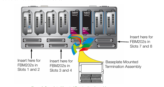
TERMINATION ASSEMBLIES
Field I/O signals connect to the FBM subsystem via
DIN rail mounted TA, or
Baseplate-mounted TA.
The TAs used with the FBM202 are described in
“FUNCTIONAL SPECIFICATIONS – TERMINATION
ASSEMBLIES” on page 8.
FUNCTIONAL SPECIFICATIONS
Input Channels
Eight isolated and independent thermocouple/mV
input channels. One isolated reference junction
temperature compensation channel.
Input Range–10.5 to +69.5 mV dc (–10.5 to +69.5 mV dc equals
0 to 64000 raw counts. Input of 71.419 mV equals
65535 raw counts (full range of module))
Reference Junction
Reference junction temperature compensation is
provided by a 4-wire 100 ohm platinum RTD
(IEC 751. Class B) at the termination assembly.
Accuracy
MILLIVOLT INPUT
±0.03% of span (±24 µV) at 25°C
RTD CHANNEL
±0.03% of span
RTD REFERENCE JUNCTION CONFORMITY
±0.25°C
THERMOCOUPLE CONFORMITY
±0.25°C
ACCURACY TEMPERATURE COEFFICIENT
±50 ppm/°C
Input Signal A/D Conversion
Each channel performs A/D signal conversion using
an independent Sigma-Delta converter.
Typical Thermocouple Types
B, E, J, K, N, R, S, T and other millivolt signals
Thermocouple Burnout Detection
Full upscale value
Input Channel Isolation
Each channel is galvanically isolated from all other
channels and earth (ground). The module withstands,
without damage, a potential of 600 V ac applied for
one minute between any channel and ground, or
between a given channel and any other channel.
CAUTION
This does not imply that these channels are
intended for permanent connection to
hazardous voltage circuits. Connection of
thes
FUNCTIONAL SPECIFICATIONS (CONTINUED)
Regulatory Compliance
ELECTROMAGNETIC COMPATIBILITY (EMC)
Eur
PHYSICAL SPECIFICATION (CONTINUED)
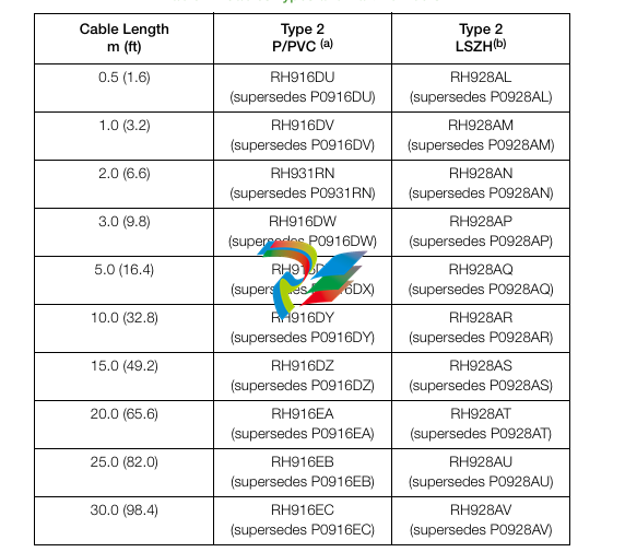
Termination Cables
CABLE LENGTHS
Up to 30 m (98 ft)
CABLE MATERIALS
Polyurethane or Low Smoke Zero Halogen
(LSZH)
TERMINATION CABLE TYPE
Type 2 - Refer to Table 2.
CABLE CONNECTION
FBM Baseplate End
37-pin D-subminiature
Termination Assembly End
25-pin D-subminiature
Construction - Termination Assembly
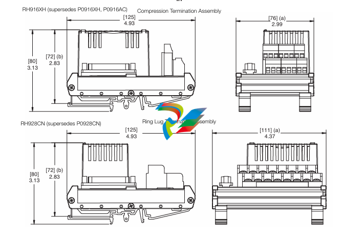
MATERIAL
DIN Rail Mounted TAs
Polyamide (PA), compression and ring lug
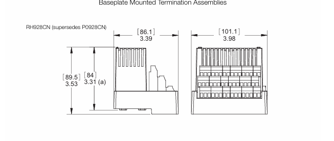
Baseplate-Mounted TAs
Polycarbonate/Acrylonitrile Butadiene
Styrene (PC/ABS), compression
TERMINATION ASSEMBLIES AND CABLES
Field I/O signals connect to the FBM subsystem via
DIN rail mounted or baseplate mounted termination
assemblies (TAs). Both these types of TAs are
electrically passive. The TAs for the FBM202 are
available in the following forms:
Compression screw type (DIN rail mounted) using
Polyamide (PA) material
Compression screw type (baseplate mounted)
using Polycarbonate/Acrylonitrile Butadiene
Styrene (PC/ABS)
Ring lug type (DIN rail mounted) using Polyamide
(PA) material
Each DIN rail mounted TA and its associated
termination cable provides a feedthrough connection
between eight 2-wire thermocouple/mV analog input
signals and an FBM202 Thermocouple/mV Input
Module. Each baseplate mounted TA provides a
Field Termination Connections
DIN RAIL TA COMPRESSION-TYPE ACCEPTED
WIRING SIZES
Solid/Stranded/AWG
0.2 to 4 mm2/0.2 to 2.5 mm2/24 to 12 AWG
Stranded with Ferrules
0.2 to 2.5 mm2 with or without plastic collar
BASEPLATE MOUNTED TA COMPRESSION -
ACCEPTED WIRING SIZES
Solid/Stranded/AWG
0.2 to 1.5 mm2/0.2 to 1.5 mm2/24 to 16
AWG
Stranded with Ferrules
0.25 to 0.75 mm2 with plastic collar
0.25 to 1.5mm2 without plastic collar
RING-LUG - ACCEPTED WIRING SIZES
#6 size connectors (0.375 in (9.5 mm))
0.5 to 4 mm2/22 AWG to 12 AWG
feedthrough connection between sixteen 2-wire
thermocouple/mV analog input signals and two
FBM202 Thermocouple/mV Input Modules.
Reference junction temperature compensation is
provided by an isolated resistance temperature
detector (RTD) that is integral to the termination
assembly. The baseplate mounted TA contains an
RTD for each FBM202.
See “FUNCTIONAL SPECIFICATIONS –
TERMINATION ASSEMBLIES” on page 8 for a list of
TAs used with the FBM202 module.
A removable termination cable connects the DIN rail
mounted TA to the FBM via a field connector on the
baseplate in which the FBM is installed. Termination
cables are available in the following materials:
Polyurethane
Low Smoke Zero Halogen (LSZH).
Termination cables are available in a variety of
lengths, up to 30 meters (98 feet), allowing the
termination assembly to be mounted in either the
enclosure or in an adjacent enclosure. See Table 2
for a list of termination cables used with the TAs for
the FBM202 module.
Upgrade Subsystem
When an FBM202 is used to replace the 100 Series
FBM02. it may use any of the appropriate termination
assemblies listed above for the FBM02’s field I/O
wiring. Alternatively, the FBM202 can accept this field
wiring through a Termination Assembly Adapter (TAA)
instead of a termination assembly. This is discussed
in Termination Assembly Adapter Modules for
100 Series Upgrade (PSS 31H-2W4)
-
 HIRSCHMANN RS20-0400M2T1SDAPHC08.0.01 Managed Switch
 -
 MACH1130 Hirschmann Industrial Switch
 -
 HIRSCHMANN 943824-002 SPIDER 5TX Industrial Ethernet Switch
 -
 HIRSCHMANN RS30-0802O6O6SDAEHC09.1.00 Managed Industrial Switch
 -
 HIRSCHMANN RS20-0400M2M2TDAEHC04.0.01 Industrial Switch
 -
 HIRSCHMANN BRS20-0600Z6Z6-STCZ99HHSES Industrial Switch
 -
 HIRSCHMANN MACH104-20TX-FR-L3P Industrial Ethernet Switch
 -
 HIRSCHMANN RS40-0009CCCCEDBPHH06.0.01 Industrial Switch
 -
 HIRSCHMANN RS2-3TX/2FX EEC Industrial Ethernet Switch
 -
 Hirschmann MACH 1020/1030 Fast/Gigabit Rack Mount Switches
 -
 HIRSCHMANN RS20-0800M2M2SDAPHC09.0.14 Industrial Switch
 -
 HIRSCHMANN RS20-1600T1T1SDAEHC09.0.04 Industrial Switch
 -
 HIRSCHMANN RSB20-0800T1T1EAABHH Industrial Switch
 -
 HIRSCHMANN MACH4002-48+4G-L3E Industrial Backbone Switch
 -
 HIRSCHMANN RS20-0400S2T1SDAE Industrial Managed Switch
 -
 HIRSCHMANN RS20-0800S2T1SDAUHC Industrial Switch
 -
 HIRSCHMANN RS20-2400S4S4SDAEHC09.0.14 industrial switch
 -
 HIRSCHMANN OS20-001200T5T5T5- TBBZ999HHNE3S 08.1.00 industrial switch
 -
HIRSCHMANN OS20-001200T5T5T5- TBBZ999HHNE3S 08.1.00 industrial switch
-
 HIRSCHMANN RS40-0009CCCCSDAEHH09.0.14 switch
 -
 Hirschmann RS20-1600T1T1SDAUHC Management-type Ethernet Switch
 -
 Hirschmann M1-8SFP Switche
 -
Hirschmann Industrial Ethernet Ruggedized Switch MACH1000 Family
-
 Basler Electric, Solid State Protective Relay, BE1-60
 -
BASLER ELECTRIC SR4A-2B15B3A Static Voltage Regulator
-
.png) BASLER ELECTRIC EXCITER DIODE MONITOR EDM-200
BASLER ELECTRIC EXCITER DIODE MONITOR EDM-200 -
.png) BASLER ELECTRIC DECS125-15-B2C5 DIGITAL EXCITATION CONTROL SYSTEM V 2.0.9
BASLER ELECTRIC DECS125-15-B2C5 DIGITAL EXCITATION CONTROL SYSTEM V 2.0.9 -
 BASLER ELECTRIC BE1-851 OVERCURRENT PROTECTION RELAY MECHANISM
 -
 Basler Electric BE1-51A / BE151A
 -
 Basler Electric BE1-40Q Loss of Excitation Relay
 -
 Basler Electric BE1-87G Variable Percentage Differential Relay
 -
 Basler Electric BE1-11 Protection System I5A3M2P2N0EA00
 -
 BASLER ELECTRIC DECS-200-1C Digital Excitation Control System
 -
 Basler Electric / Kohler BE1-11g Generator Protection Relay G5A3M2J2N0E000
 -
BASLER ELECTRIC DECS125-15 DIGITAL EXCITATION CONTROL SYSTEM
-
 BASLER ELECTRIC BE1-951 OverCurrent Protecton System
 -
Basler Electric DECS-200-1L Digital Excitation Control System
-
 Basler Electric DGC-2020HD-5NS1DNSBA Digital Genset Controller -
 -
 BASLER ELECTRIC BE1-81T1EE1WA0N1F / BE181T1EE1WA0N1F
 -
 BASLER ELECTRIC BE1-25M1EA6PN5R1F / BE125M1EA6PN5R1F
 -
 BASLER ELECTRIC DECS-250-LN1SN1N DIGITAL EXCITATION CONTROL SYSTEM
 -
Basler Electric DECS-250-CN2CN 1N Digital Excitation Control System Unit
-
 BASLER ELECTRIC DECS-300-C0N0 DIGITAL EXCITATION CONTROL SYSTEM
 -
 BASLER ELECTRIC BE1-87T-A1E-A1J-D0S1F / BE187TA1EA1JD0S1F
 -
BASLER ELECTRIC BE1-11-G6D1M0J2P0E000 Protection System
-
 BASLER ELECTRIC BE1-GPS100-E4N1H1N GENERATOR PROTECTION SYSTEM
 -
 Jaquet Relay card (Auxiliary module) FTV 3090 377Z-03985
 -
 Jaquet Trip Chain Control card FTBU 3034 377Z-05030
 -
 Jaquet with input card -E04 FTFU 3024 -E04 377Z-05855
 -
 Jaquet with input card -E03 FTFU 3024- E03 377Z-03983
 -
 Jaquet FTFU 3024- E02 377Z-03982 with input card -E02
 -
 Jaquet FTFU 3024-E01 377Z-03981 with input card -E01
 -
 Hirschmann RS20-2400T1T1SDAE Industrial Managed Ethernet Switch
 -
 Hirschmann BELDEN EAGLE30-04022O6TT999SCCV9HSE3F
 -
 Hirschmann MM3-2FXS2/2TX MICE Media Module
 -
 Hirschmann RS20-1600M2M2SDAPHC08.0.05 Industrial Managed Switch
 -
 Hirschmann OZD Profi 12M G12-1300 PRO Fieldbus Repeater
 -
 Hirschmann SPIDER 4TX/1FX-ST EEC Industrial Ethernet Switch
 -
 Hirschmann MM2-2FXM3/2TX1 MICE Media Module
 -
 Hirschmann RS20-2400M2M2SDAPHC09.0.14 Industrial Switch
 -
 Hirschmann RS20-0400M2M2SDAEHC07.1.05 OpenRail Switch
 -
 Hirschmann OZD Profi 12M G12-EEC Fieldbus Repeater
 -
 HIRSCHMANN MDA422-1/2-3.5c-23/46 sensor
 -
Hirschmann RS30-2402T1T1SDAUHC Managed Industrial Switch
-
 Hirschmann OZD GENIUS G12 Industrial Switche
 -
 Hirschmann OZD 485 G12-1300 PRO Fieldbus Repeater
 -
 Hirschmann MM2-2FXM2 MICE Media Module
 -
 Hirschmann RS20-1600S2T1SDAUHC Managed Industrial Switch
 -
 Hirschmann MS20-0800SAAEHH04.2.04 MICE Switch
 -
 Hirschmann SPIDER 4TX/1FX EEC Unmanaged Industrial Switch
 -
 HIRSCHMANN MS4128-L3P EEC Managed Industrial Ethernet Switch
 -
 HIRSCHMANN RS20-0400M2T1SDAPHC08.0.01 Managed Switch
 -
 ETEL EA-S0M-400-40/80A-0000-00 AccurET Modular Power Supply
 -
 ETEL EA-B0I-0-0-0000-00 Backplane Interface Board
 -
 ETEL EA-P2M-400-15/40A-0100-00 Position Controller
 -
ETEL EA-P2M-400-15/40A-0000-00 Position Controller
-
 ETEL EA-P2M-400-10/20A-0100-01 Position Controller
 -
 ETEL EA-P2M-400-10/20A-0000-01 Position Controller
 -
 ETEL EA-P2M-400-5/10A-0100-01 Position Controller
 -
 ETEL EA-P2M-048-2.5/5A-0000-01 Modular Position Controller
 -
 ETEL EA-S0M-300-40/80A-0000-00 Power Supply Module
 -
 ETEL EA-P2M-300-07/15A-0100-01 Position Controller
 -
 ETEL EA-P2M-300-07/15A-0000-01: Modular Position Controller
 -
 ETEL EA-P2M-300-4/7.5A-0100-01 Overview
 -
 Basler Electric MOC2. Motor Operated Potentiometer
 -
 Basler Electric BE1-11 RTD Module, Resistance Temperature Detector
 -
 Basler Electric RDP-110C, Remote Display Panel
 -
 Basler Electric VRM-2020. Voltage Regulation Module
 -
 Basler Electric IDP-1500. Interactive Display Panel
 -
 Basler Electric AEM-2020. Analog Expansion Module
 -
 Basler Electric IDP-2020. Interactive Display Panel
 -
 Basler Electric CEM-2020. Contact Expansion Module
 -
 Basler Electric CEM-125. Contact Expansion Module
 -
 Basler Electric BE2000E, Digital Voltage Regulator
 -
 Basler Electric SMC-150. Synchronous Motor Controller
 -
 Basler Electric AVC125-10. Voltage Regulator
 -
 Basler Electric BE1-25. Sync-Check Relay
 -
 Basler Electric DGC-2020ES, Digital Genset Controller
 -
 ETEL EA-P2M-400-5/10A-0000-01 Position Controller
 -
 Basler Electric BE1-64F, Ground Fault Relay
 -
 Basler Electric BE1-79M, Multi Shot Reclosing Relay
 -
 Basler Electric BE1-81O/U, Digital Frequency Relay
 -
 Basler Electric BE1-87B, High Impedance Bus Differential Relay
 -
 Basler Electric BE1-79A, Reclosing Relay
 -
 Basler Electric BE1-27. BE1-59. BE1-27/59. Voltage Relay
 -
 Basler Electric SMC-250. Synchronous Motor Controller
 -
 Basler Electric SGC-250N, Synchronous Generator Controller
 -
 Basler Electric SGC-250. Synchronous Generator Controller
 -
 Basler Electric BE1-50/51 Plug and Play and Retrofit Relays
 -
 Basler Electric DECS-2100. Digital Excitation Control System
 -
 Basler Electric DECS-250E, Digital Excitation Control System
 -
 Basler Electric BE1-700V, Voltage Only Digital Protective Relay
 -
 Basler Electric DECS-250. Digital Excitation Control System
 -
 Basler Electric DECS-450. Digital Excitation Control System
 -
 Basler Electric DECS-150. Digital Excitation Control System
 -
 Basler Electric ES-49. Temperature Relay
 -
 Basler Electric ES-81O/U, ES-81O,ES-81U Overfrequency Relay
 -
Basler Electric ES-74V, DC Voltage Sensing Relay
-
Basler Electric ES-27/59. Under/Overvoltage Relay
-
 Basler Electric ES-27. Undervoltage Relay
 -
 Basler Electric ES-25. Sync-Check Relay
 -
 Basler Electric ES-47, ES-47N Phase Sequence Relay
 -
Basler Electric ES-37.ES-37/51 Undercurrent Relay
-
 Basler Electric ES-32. Reverse Power Relay
 -
Basler Electric ES-59. Overvoltage Relay
-
 Basler Electric ES-55. Power Factor Relay
 -
 Basler Electric DGC-2020HD, Digital Genset Controller
 -
 Basler Electric BE1-FLEX, Protection, Automation, and Control System


