
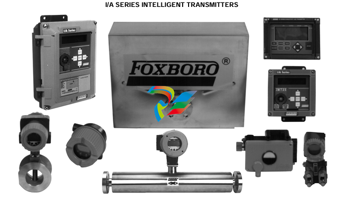
Foxboro 0 to 20 mA Output Interface Module (FBM44)
I/A Series® Hardware
Dual Baud Rate Intelligent Transmitter/
0 to 20 mA Output Interface Module (FBM44)
The Dual Baud Rate Intelligent Transmitter (IT)/0 to
20 mA Output Interface Fieldbus Module contains
four individual Intelligent Transmitter interface
channels and four 0 to 20 mA dc analog output
channels. The module is a main type and
independently connects to the redundant Fieldbus.
Intelligent Transmitter (IT) Interface Channels
Each IT interface channel provides internally isolated
power and communication capabilities to an IT over a
single twisted-pair wire. The module also allows the
use of an external power supply to power the IT.
The use of an external power supply common to two
or more loops requires the use of a Cable Balun
Module to maintain digital communication line
balance. The baud rate is software-selectable with all
channels at the same baud rate. Each module
provides bi-directional digital communications at
4800 baud rate between the IT and the system
redundant Fieldbus or provides bi-directional digital
communications at 600 baud rate while allowing
simultaneous 4 to 20 mA analog signal for use in
other applications (for example, to an emergency
shutdown system)
The module is an IT host, enabling the system to
receive digital messages from the transmitter in
engineering units. Each message is received ten
times per second at 4800 baud and two times per
second at 600 baud and contains:
• Two measured variables (that is, primary
pressure and transmitter temperature) in IEEE
32-bit floating-point
• Security information
• Diagnostics
• Message checking.
This information is available to all elements of the
system.
Since the communications are bi-directional, the
system can display the output, transmitter
temperature (°C and °F), and continuous self
diagnostics. Additionally, the following information can
be displayed or reconfigured from the console or a
Hand-Held Terminal (PSS 2A-1Z3 A):
• Output in engineering units
• Fail-safe state
• Tag number, name and location
• Device name (letterbug)
• Last calibration date
• Two levels of upload/download capabilities.
The IT interface portion of the module executes the
Intelligent Transmitter application program. The
configurable options for this program are Fieldbus
Switching Enable and Fieldbus Switching Time.
Output Channels
Each output channel drives an external load and
produces a 0 to 20 mA output. Each output channel
performs the signal conversion required to interface
the electrical output signals to field actuators from the
redundant Fieldbus.
The output channel portion of the module executes
the analog I/O application program. The configurable
options for this program are Fail-Safe Configuration
(Hold/Fallback), Analog Output Fail-Safe Fallback
Data (on a per channel basis), Fieldbus Switching
Enable and Fieldbus Switching Time.
An optional style of termination cable assembly which
is available includes built-in bypass jacks for each
output channel on the front connector of the Fieldbus
Module. Jacks accept a bypass plug from the
I/A Series Output Bypass Station or other external
20 mA source. This option should be considered for
applications where maintaining output is desired
during maintenance operations, for example, when
replacing a failed module.
Common Characteristics
POWER REQUIREMENTS
Input Voltage (Redundant)
26 to 42 V dc (nominal)
Consumption
11 W (maximum)
Heat Dissipation
8 W (maximum)
ISOLATION
FUNCTIONAL SPECIFICATIONS
Transmitter Channels (Cont.)
MAXIMUM DISTANCE (INTERFACE TO
TRANSMITTER)* (SHIELDED TWISTED-PAIR
WIRES, OR AT MINIMUM TWISTED-PAIR WITH
OVERALL SHIELD)
The module can withstand, without damage, a
potential of 600 V ac applied for one minute
between any channel and earth (ground), or
between a given channel and any other channel.
NOTE
This does not imply that these channels are
intended for permanent connection to hazardous
voltage circuits. Connection of these channels to
voltages greater than 30 V ac or 60 V dc violates
electrical safety code requirements and may
expose users to electric shock.
COMMUNICATION
Via a redundant Fieldbus
Transmitter Channels
INTERFACE
4 isolated and independent channels
ERROR CHECKING
CCITT 2 byte CRC
COMMUNICATIONS
Non-redundant, point-to-point, master/slave,
asynchronous, half-duplex at a software-selectable
baud rate of 600 or 4800 baud. All 8 input channels
must be configured at the same baud rate
(600 baud for 4 to 20 mA transmitters or 4800 baud
for digital transmitters).
SPEED
10 messages per second at 4800 baud, or
2 messages per second at 600 baud
610 m (2000 ft) (shielded twisted-pair wires) at
4800 baud, or 1800 m (6000 ft) at 600 baud
MAXIMUM LOOP RESISTANCE
500 Ω (not including the transmitter). The
maximum resistance between the Hand-Held
Terminal (HHT) and the transmitter is 350 Ω.
TRANSMITTER INTERNAL POWER
24 V dc +4%, -2%, source resista
| User name | Member Level | Quantity | Specification | Purchase Date |
|---|


-
 MOOG G123-825-001 BUFFER AMPLIFIER
 -
 Motorola MVME5100 Series VME Processor Modules
 -
 Motorola MVME162 Embedded Controller
 -
 HIMatrix Safety-Related Controller System Manual for the Modular Systems
 -
 Motorola MVME2400 Series VME Processor Module
 -
 Sieger System 57
 -
 KONGSBERG MRU product line continuation
 -
 Woodward easYgen-3100/3200 Genset Control for Multiple Unit Operation
 -
 Woodward MFR 300 Multifunction Relay / Measuring
 -
 ABB AX410, AX411, AX413, AX416, AX418, AX450, AX455 and AX456 Single and dual input analyzers for low level conductivity
 -
 ABB AX410, AX411, AX416, AX450 and AX455 Single and dual input analyzers
 -
 Woodward easYgen-1400 Technical Manual Genset Control
 -
 Woodward easYgen-400 Operation Manual Genset Control
 -
 Woodward High Output Digital Valve Positioner (DVP)DVP5000/DVP10000/DVP12000
 -
 Woodward High Output Digital Valve Positioner DVP5000 and DVP10000
 -
 Woodward TG611-13/-17 Overspeed Test Device Conversion Kit
 -
 Woodward MicroNet Safety Module (MSM)
 -
 Woodward 2301A Electronic Load Sharing and Speed Control 9905/9907 Series
 -
 Woodward-Service Bulletin 01671
 -
 UniOP eTOP40B 12.1” TFT color display
 -
 UniOP eTOP40 TFT Color display
 -
 UniOP eTOP33B 10.4” TFT color display
 -
 UniOP eTOP33C eTOP33-0050 Resistive touchscreen
 -
UniOP eTOP30. eTOP32 eTOP32-0050 Human-machine interface equipment
-
 UniOP eTOP20B and eTOP21B eTOP20B-0050
 -
 UniOP eTOP12 eTOP12-0050 Advanced human-machine interface equipment
 -
 UniOP eTOP11 eTOP11-0050 HMI
 -
 UniOP eTOP06C HMI
 -
 UniOP eTOP06 HMI
 -
 UniOP eTOP05EB eTOP05EB-DF45 HMI
 -
 UniOP eTOP05. eTOP05P Human-machine interface equipment
 -
 UniOP eTOP03 eTOP03-0046
 -
 UniOP eTOP507 507U2P1 eTOP Series 500 Human-Machine Interface
 -
 UniOP eTOP307
 -
 UniOP ETT-VGA Human-machine interface touch unit
 -
 UniOP ePAD32B, ePAD33B and ePAD33BT ePAD33B-0350
 -
 UniOP ePAD05 and ePAD06
 -
 UniOP CP02R-04 Human-machine interface
 -
 UniOP ERT-16 - Industrial PLC Workstation
 -
 UniOP ePAD03 and ePAD04
 -
 UNIOP EPALM10-DA71 state-of-the-art handheld HMI
 -
 Watlow SERIES CLS200 SPECIFICATION SHEET
 -
 Detailed Explanation of B&R Power Panel 300/400: The Core of Industrial Automation Control
 -
 YOKOGAWA Models ANB10S, ANB10D, ANR10S, ANR10D Node Units (for FIO)
 -
 Woodward ESDR 4 Current Differential Protection Relay
 -
 Woodward easYgen-3000 Genset Control for
 -
 Woodward CPC-II Current-to-Pressure Converter
 -
 Woodward 8290-189-EPG-installation-manual 8290-044
 -
 Woodward Product Change Notification 06946A
 -
 Woodward Product Change Notification 06912
 -
 Fisher™ 4660 High-Low Pressure Pilot
 -
 Flexible digital protection and control equipment SYMAP®
 -
 Woodward 723PLUS Digital Control
 -
 Woodward 505 Digital Controller For steam turbineses
 -
 Woodward 85018V2 505E Digital Governor for Extraction Steam Turbines
 -
Woodward 85018V1 Turbine Control Parameters
-
Woodward 26871 505 Enhanced Digital Control for Steam Turbines
-
 Woodward 03365 505E (Extraction / Admission)
 -
 KONGSBERG RMP420-Remote Multipurpose Input/Output
 -
 KONGSBERG RCU501 Remote Controller Unit
 -
 KONGSBERG RCU500 Remote Controller Unit
 -
 K-Gauge TOP KONGSBERG Tank Overfill Protection SystemFeatures
 -
 Kongsberg DPS112 DGNSS (DGPS/DGLONASS) sensor
 -
 Kongsberg d0000930-presafe-atex-report signed
 -
 HIMax TECHNICAL FACTS X Series
 -
 GE Multilin F650
 -
 GE MIF II - Legacy
 -
 GE PQM II Power QualIty Meter
 -
 Hydran 201Ti Mark IV Essential DGA monitoring for transformers
 -
 alstom AMS42/84 5B Amplifier SystemAmplifier Technology at its Best.
 -
 GE VMIVME-5576 Fiber-Optic Reflective Memory with Interrupts
 -
 GE Multilin 750/760 - Legacy Feeder Protection System
 -
 GE Fanuc Automation VMICPCI-7806 Specifications
 -
 VMIVME-7807 VME-7807RC* Intel® Pentium® M-Based VME SBC
 -
 GE Fanuc Automation VMIVME-7750 Specifications
 -
 FOXBORO Compact FBM240. Redundant with Readback, Discrete
 -
 FOXBORO FBM208/b, Redundant with Readback, 0 to 20 mA I/O Module
 -
 FOXBORO FBM201e Analog Input (0 to 20 mA) Interface Modules
 -
 Foxboro DCS FBM206 Pulse Input Module
 -
 FOXBORO FBM216 HART® Communication Redundant Input Interface Module
 -
 FOXBORO Z-Module Control Processor 270 (ZCP270)
 -
 FOXBORO Fieldbus Communications Module, FCM10Ef
 -
 FOXBORO Fieldbus Communications Module, FCM10E
 -
 Foxboro DCS Compact FBM241/c/d, Redundant, Discrete I/O Modules
 -
Foxboro FBM223 PROFIBUS-DP™ Communication Interface Module
-
 Foxboro DCS FBM204. 0 to 20 mAI/OModule
 -
Foxboro FBM239, Discrete 16DI/16DO Module
-
Foxboro FBM202 Thermocouple/mV Input Module
-
 Foxboro E69F Current-to-Pneumatic Signal Converter
 -
 EMERSON M-series Intrinsically Safe I/O
 -
 MVME6100 Series VMEbus Single-Board Computer
 -
 Configuration for AMS 6500 Protection Monitors
 -
 Ovation™ Controller Model OCR1100 (5X00481G04/5X00226G04)
 -
 ABB UCU-22, UCU-23 andUCU-24control units
 -
 ABB force measurement
 -
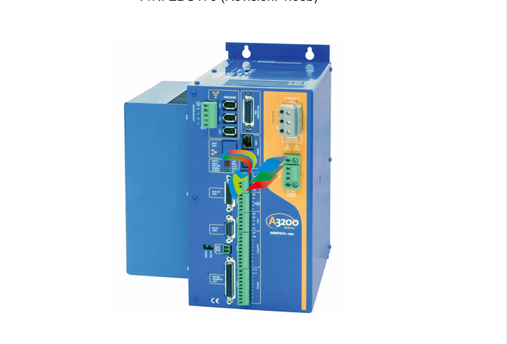
 AEROTECH Ndrive MP Hardware Manual
 -
 AEROTECH Ndrive HPe 10/20/30
 -
 AEROTECH Ndrive CP Hardware Manual
 -
 AEROTECH Ndrive Linear Series Digital Servo Amplifiers – Linear
 -
 AEROTECH Ndrive HP 10/20/30 P/N: EDU170
 -
 AEROTECH EDU176_Ndrive_HL
 -
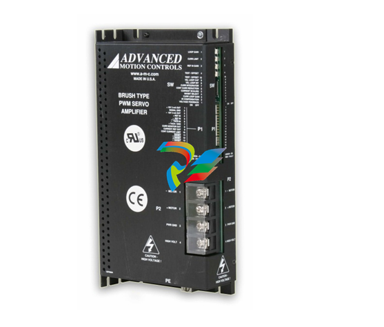 ADVANCEDMOTION CONTROLS Analog Servo Drive 120A10
 -
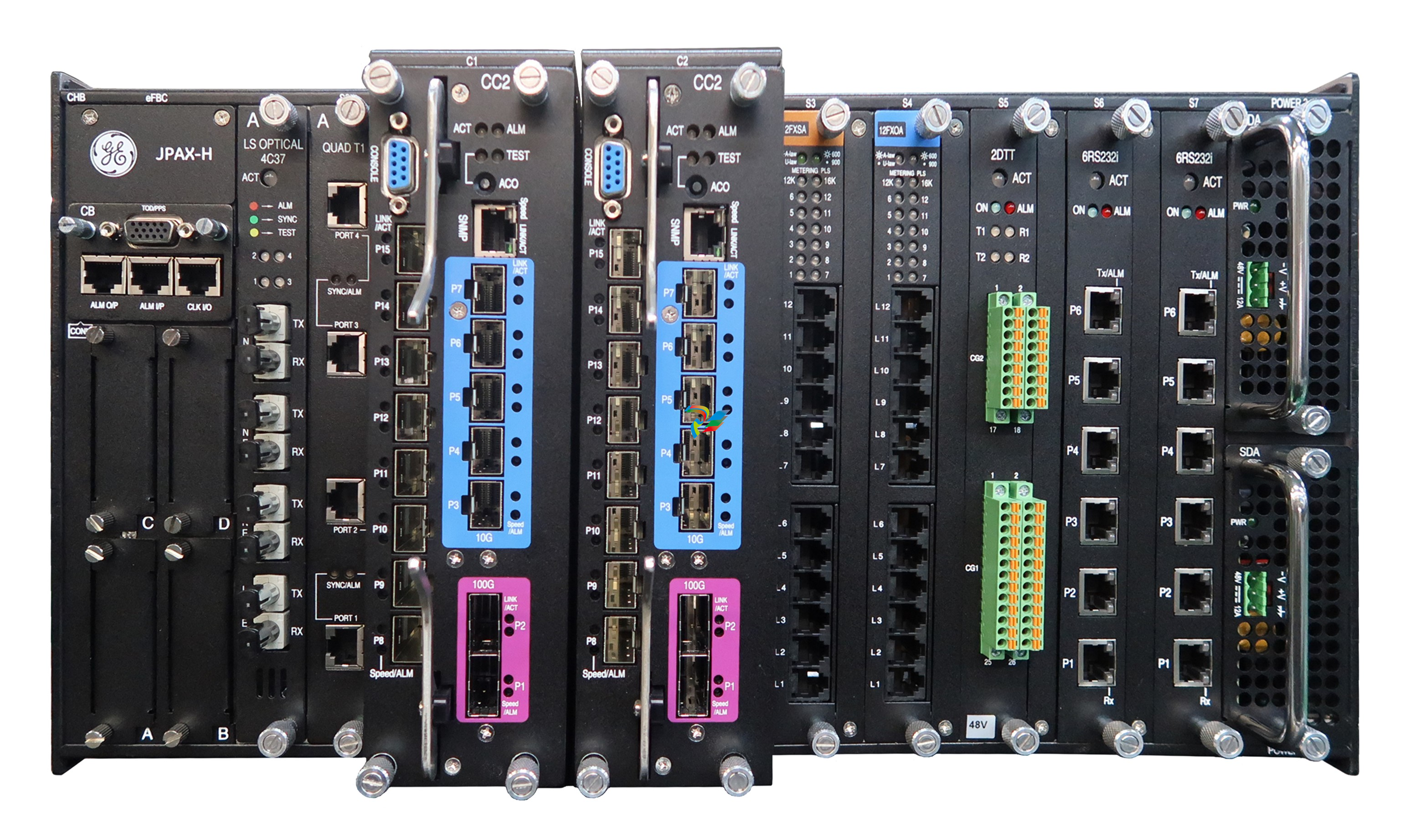 GE JPAX-H
 -
 GE JPAX family
 -
 GE Industry Leading Experience
 -
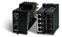 GE Ether-1000 Unit
 -
 GE Cyber Secured Service Unit
 -
 GE Lentronics E1MXe Multiplexer
 -
 GE TTMX Teleprotection Terminal
 -
 GE Lentronics T1 Multiplexer
 -
 GE Lentronics JungleMUX SONET Multiplexer
 -
 GE Lentronics E1MX Multiplexer
 -
GE Lentronics TN1Ue SDH Multiplexer
-
 GE Lentronics TN1U SDH Multiplexer
 -
 GE Gridcom DXC Family Access and Transmission Multiplexer
 -
 GE Advanced Network Management Simplifying Optical Networks
 -
 GE Lentronics VistaNET Network Management System (NMS)
 -
 ABB System Controller Connect
 -
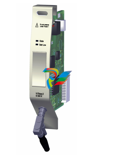
 Ethernet Module EI 803F ABB
 -
 Ethernet Modules EI 802F ABB
 -
ABB Ethernet Modules EI 801F
-
 ABB Power Supply SD 802F / SD 812F
 -
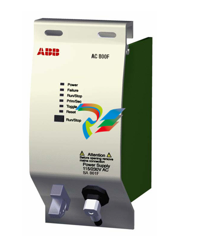 ABB Power Supply SA 801F / SA 811F
 -
 ABB Basic Unit PM 802F /PM 803F
 -
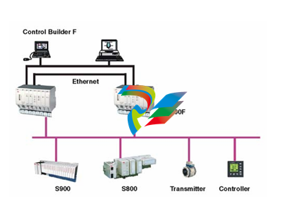 ABB AC 800F Controller Redundancy
 -
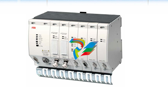 ABB Freelance800F AC800F Data Sheet
 -
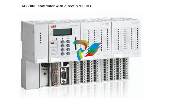 ABB Compact control system replaces PLCs using AC 700F
 -
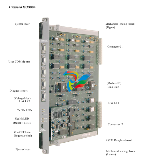 ABB Triguard SC300E MSR04XI


