
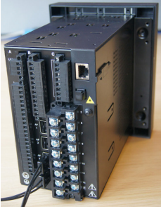
GE350 Feeder Protection System
GENERAL SAFETY PRECAUTIONS - 350
• Failure to observe and follow the instructions provided in the equipment manual(s)
could cause irreversible damage to the equipment and could lead to property
damage, personal injury and/or death.
• Before attempting to use the equipment, it is important that all danger and caution
indicators are reviewed.
• If the equipment is used in a manner not specified by the manufacturer or
functions abnormally, proceed with caution. Otherwise, the protection provided by
the equipment may be impaired and can result in Impaired operation and injury.
• Caution: Hazardous voltages can cause shock, burns or death.
• Installation/service personnel must be familiar with general device test practices,
electrical awareness and safety precautions must be followed.
• Before performing visual inspections, tests, or periodic maintenance on this device
or associated circuits, isolate or disconnect all hazardous live circuits and sources
of electric power.
• Failure to shut equipment off prior to removing the power connections could
expose you to dangerous voltages causing injury or death.
• All recommended equipment that should be grounded and must have a reliable
and un-compromised grounding path for safety purposes, protection against
electromagnetic interference and proper device operation.
• Equipment grounds should be bonded together and connected to the facility’s
main ground system for primary power.
• Keep all ground leads as short as possible.
• At all times, equipment ground terminal must be grounded during device
operation and service.
• In addition to the safety precautions mentioned all electrical connections made
must respect the applicable local jurisdiction electrical code.
• Before working on CTs, they must be short-circuited.
• LED transmitters are classified as IEC 60825-1 Accessible Emission Limit (AEL) Class
1M. Class 1M devices are considered safe to the unaided eye. Do not view directly
with optical instruments.
• This product uses optical electronic devices (line or point sensors) to sense arc
flash fault conditions. It is recommended to follow proper housekeeping measures
and establish a regularly scheduled preventive maintenance routine to ensure
proper device operation.
• This product itself is not Personal Protective Equipment (PPE). However, it can be
used in the computation of site-specific arc flash analysis when the arc flash
option is ordered. If a new appropriate Hazard Reduction Category code for the
installation is determined, the user should follow the cautions mentioned in the arc
flash installation section.
• This guide is intended to provide protective relay application guidance to mitigate
arc flash incident energy. This guide does not endorse energized work. This guide
does not claim that protective relaying can totally protect personnel from the
dangers of an arc flash. The only way to completely prevent injury from arc flash
events is to de-energize the equipment and properly follow safe lockout/tagout
procedures to ensure the equipment remains de-energized.
Safety words and definitions
The following symbols used in this document indicate the following conditions
Note Indicates a hazardous situation which, if not avoided, will result in death or serious
injury.
Note Indicates a hazardous situation which, if not avoided, could result in death or serious
injury.
Note Indicates a hazardous situation which, if not avoided, could result in minor or
moderate injury.
Note Indicates practices not related to personal injury
Overview
The 350 is a microprocessor-based relay for primary and backup over-current protection
of medium and low voltage distribution feeders. The relay is also suitable for providing
over-current and backup protection for small and medium size motors, transformers,
generators, and distribution bus-bars. The small footprint and the withdrawable option
make the 350 relay ideal for panel mounting on either new or retrofit installations. The
combination of proven hardware, a variety of protection and control features, and
communications, makes the relay ideal for total feeder protection and control. Equipped
with serial (RS485), USB, and Ethernet ports with the possibility of adding redundancy
(IEC62439, PRP and HSR), and a wide selection of protocols such as Modbus, DNP3.0, IEC
60870-5-103, 60870-5-104, IEC61850 GOOSE, OPC-UA, the 350 relay is the best-in-class
for MCCs and PCCs, SCADA and inter-relay communications. The 350 relay provides
excellent transparency with respect to power system conditions and events, through its
four-line 20-character display, as well as the EnerVista 3 Series Setup program.
Conveniently located LEDs provide indication of relay operation, alarm, and pickup, as well
as breaker, and relay status.
The 350 relay provides the following key benefits:
• Withdrawable small footprint – saves on rewiring and space. (non-draw out version is
also available)
• Multiple protection groups with the added flexibility of switching through a wide
selection of overcurrent protection and control features.
• Fast setup (Quick Setup) menu for power-system setup and a simple overcurrent
protection configuration.
• Large four-line LCD display, LEDs, and an easy-to-navigate keypad.
• Multiple communication protocols for simultaneous access when integrated into
monitoring and control systems.
Description of the 350 Feeder Protection System
CPU
Relay functions are controlled by two processors: a Freescale MPC5554 32-bit
microprocessor measures all analog signals and digital inputs and controls all output
relays; a Freescale MPC520B 32-bit microprocessor controls all the Ethernet
communication protocols.
Analog Input and Waveform Capture
Magnetic transformers are used to scale-down the incoming analog signals from the
source instrument transformers. The analog signals are then passed through a 960 Hz low
pass anti-aliasing filter. All signals are then simultaneously captured by sample and hold
buffers to ensure there are no phase shifts. The signals are converted to digital values by a
12-bit A/D converter before finally being passed on to the CPU for analysis.
Both current and voltage are sampled thirty-two times per power frequency cycle. These
‘raw’ samples are scaled in software, then placed into the waveform capture buffer, thus
emulating a fault recorder. The waveforms can be retrieved from the relay via the EnerVista
3 Series Setup software for display and diagnostics.
Frequency
Frequency measurement is accomplished by measuring the time between zero crossings
of the Bus VT phase A voltage. The signals are passed through a low pass filter to prevent
false zero crossings. Sampling is synchronized to the Va-x voltage zero crossing which
results in better co-ordination for multiple 350 relays on the same bus.
Phasors, Transients, and Harmonics
Current waveforms are processed four times every cycle with a DC Offset Filter and a
Discrete Fourier Transform (DFT). The resulting phasors have fault current transients and
all harmonics removed. This results in an overcurrent relay that is extremely secure and
reliable; one that will not overreach.
Processing of AC Current Inputs
The DC Offset Filter is an infinite impulse response (IIR) digital filter, which removes the DC
component from the asymmetrical current present at the moment a fault occurs. This is
done for all current signals used for overcurrent protection; voltage signals bypass the DC
Offset Filter. This filter ensures no overreach of the overcurrent protection.
The Discrete Fourier Transform (DFT) uses exactly one sample cycle to calculate a phasor
quantity which represents the signal at the fundamental frequency; all harmonic
components are removed. All subsequent calculations (e.g. RMS, power, etc.) are based
upon the current and voltage phasors, such that the resulting values have no harmonic
components.
Protection Elements
Protection elements are processed up to four times every cycle to determine if a pickup
has occurred or a timer has expired. The protection elements use RMS current/voltage,
based on the magnitude of the phasor. Hence, protection is impervious to both harmonics
and DC transients.
NOTE
NOTE: Arc Flash protection elements are processed up to 8 times every cycle.
Product identification
The product identification label is located on the side panel of the 350 . This label indicates
the product model, serial number, and date of manufacture.
Figure 2-3: 350 Product labels

The pink color text (i.e. Model, Serial Number, Instruction Manual, MFG. Date) is for
reference only. The text can vary.
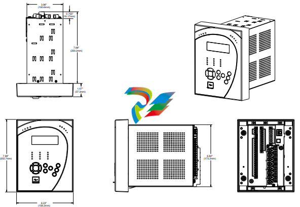
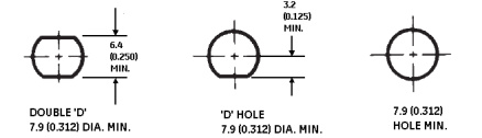
Mounting
Standard panel mount The standard panel mount and cutout dimensions are illustrated below.
CAUTION: To avoid the potential for personal injury due to fire hazards, ensure the unit is
mounted in a safe location and/or within an appropriate enclosure.
1. Mount the collar of required depth (1.375” or 3”) to the unit (captive or non-drawout)
using 4 screws (see above).
2. Mount the combination of unit and collar to the panel using 4 screws as shown above.
Figure 2-7: Mounting tabs (optional)
1. From the front of the panel, slide the empty case into the cutout until the bottom tab
clicks into place (see above).
2. From the rear of the panel screw the case into the panel at the 8 screw positions
shown above.
3. If added security is required, bend the retaining "V"tabs outward, to about 90°. These
tabs are located on the sides of the case and appear as shown above.
The relay can now be inserted and can be panel wired.
P20 Cover (optional)
The IP20 cover minimizes potential dangers to users by preventing finger contact with
electrical connections at the back of the 3 Series drawout units.
Attaching the cover
The steps for attaching the IP20 cover (optional) to the drawout unit are as follows:
Figure 2-13: IP20 Cover mounting - Drawout unit only
1. Place 4 custom standoffs (item#1) using the suggested tightening torque of 8lb-in in
the following order:
A. Remove the 2 mounting screws near letters A and C, of label ABC (item#2), and
mount 2 standoffs.
B. Remove the 2 mounting screws near the letters B and E, of label ABCDE (item#3),
and mount 2 standoffs.
2. Place the IP20 cover (item#4) and secure it with 4 screws (item#5) using the suggested
tightening torque of 8lb-in.
NOTE
NOTE: Make sure the device terminals are wired before placing the cover. Use the 5 slots located
on each side of the cover to guide the wires outside of the cover.
Retrofit kit for IP20
Before attaching the cover, remove the old labels from the device (see item#2 and item#3)
and replace them with the new labels from the retrofit kit. Attach the cover as described in
the previous section.
Arc flash sensors
Arc flash sensors house the fiber optics that are used to detect the arc flash. Mounting
details depend on the sensor type (point or loop).
For detailed installation, testing and maintenance guidance for Arc Flash sensors, see GET20057 3 Series Arc Flash Application Note.
If the relay is used in the computation for reducing the Hazard Reduction Category
code, operands for sensor failures must be assigned to an auxiliary output relay which
must be connected into the control logic of the breaker equipment to ensure safe
operations when the output relay is asserted. In the event of this assertion, the Hazard
Reduction Category code cannot be maintained unless backup protection is continuing
to maintain it.
CAUTION: This product uses optical electronic devices (line or point sensors) to sense arc flash
fault conditions. It is recommended to follow proper housekeeping measures &
establish a regularly scheduled preventive maintenance routine to ensure proper
device operation. For maintenance recommendations, see GET-20057 3 Series Arc
Flash Application Note
Arc flash sensors are available in two different configurations, point and loop. Loop sensors
can be used with a black-coated sensor fiber extension to connect the ends of the loop
sensor to the 350 relay through panels up to 51 mm (2 inches) thick.
Arc Flash sensor fiber is pressure sensitive and must be handled carefully to avoid
damage. Read the following guidelines fully before proceeding.
Care must be taken when handling the Arc Flash sensor fiber, which can be damaged if
twisted, bent, or clamped tightly during installation.
• Do not bend sensor fiber sharply, or with a radius of less than 35 mm (1.3 inches).
Sharp bends can damage the fiber. Do not pull or tug loops of sensor fiber, as sharp
bends may result.
• Do not clamp sensor fiber tightly during installation. Sensor fiber should be held in
place loosely for the best long-term performance. Avoid over-tightening ties which
may deform or break the sensor fiber.
• Do not pull or tug sensor fiber with force, as this may cause internal damage or
separate the fiber from the cable connector.
• Do not twist the sensor fiber, as twisting can damage the fiber resulting in
substandard performance.
• Do not attach sensor fiber directly to the bus or other live conductors.
• Avoid surface temperatures above 70 °C or 158 °F to prolong the life of the fiber.
• Secure all sensor fibers (loosely but securely) away from any moving parts.
The point sensor fiber includes a duplex connector to connect to the back of the 350 relay
on one end, and a compressed slim connector that connects to the sensor itself on the
other end.
Before installing the AF sensor units, ensure that all other drilling and installation is
complete to minimize possible damage to the sensitive unit and connected sensor fiber
cable. Choose a location for the sensor clear of any obstructions that could shield the
sensor from arc flash light.
FASTPATH: Review the sensor fiber handling guidelines above.
Sensor fiber should be held in place loosely for the best long-term performance. Avoid
over-tightening ties which may deform or break the sensor fiber.
General installation:
1. Choose a location for the point sensor.
Arc flash point sensors should be installed clear of any obstructions that could shield
the sensor from arc flash light, and less than 2m (6ft 6") from any potential arc flash
source.
The sensor head should be pointed towards the most likely source of arc flash.
For further guidance selecting point sensor locations, see GET-20057 3 Series Arc
Flash Application Note.
2. Remove the slim connector from the point sensor assembly.
3. Carefully route the duplex sensor fiber from the point sensor location to the back of
the relay unit, minimizing loops and curves for the strongest possible signal. Ensure all
sensor fiber handling precautions are followed.
The slim connecter fits through holes with a diameter of 11 mm or greater, and can be
threaded through holes drilled in any panels between the relay and arc flash detection
location.
NOTE
NOTE: Install protective grommets when routing sensor fiber through metal walls.
4. Mount the point sensor using either a cable tie mount or through-hole mount, as
detailed below.
5. Reconnect the slim connector to the point sensor.
Arc flash point sensors can be installed in one of two ways, using a cable tie mount or a
through-hole mount.
Cable tie mount:
• Requires a 2.5-mm-wide cable tie.
• Mount the sensor on a stick or similar using the cable tie, as shown in the following
figure.
Through-hole mount
• Requires a standard or self-tapping M3 screw, and optionally an M3 washer.
• Mount the sensor through a 10 mm hole made in the surface of any mechanical
structure inside the switchgear or on the surface of one side of the switchgear itself,
as shown in the following figure.
Make sure there is no dirt or dust inside the point sensor or on the surface because it
reduces the capturing efficiency of the device, increases its transmission loss, or both. If
the point sensor is covered with dust, clean it by blowing or wiping the dust off the point
sensor.
FASTPATH: The material of the point sensor is not affected by water-based cleaning agents, dish
soap, or organic solvents with an alcohol (ethanol) base. Do not use solvents or solvent
mixtures that contain acids because they can attack or dissolve the optical plastic
material.
Before installing the AF sensor units, ensure that all other drilling and installation is
complete to minimize possible damage to the sensitive unit and connected sensor fiber
cable.
FASTPATH: Review the sensor fiber handling guidelines above.
Sensor fiber should be held in place loosely for the best long-term performance. Avoid
over-tightening ties which may deform or break the sensor fiber.
FASTPATH: The loop sensor fiber can be connected directly to the 350 relay without a sensor fiber
extension, however, care must be taken to ensure correct alignment of the loop sensor
single connectors into the 350 light sensor input.
Installing the loop sensor fiber without an extension:
1. Plan the path of the loop sensor fiber, looping through the chamber or chambers
requiring arc flash detection. See GET-20057 3 Series Arc Flash Application Note for
detailed examples of loop sensor installation.
2. Ensure that both ends of the loop remain close together and can reach the 350 relay
light sensor inputs.
3. Install the loop sensor carefully, following all sensor fiber handling guidelines.
4. Plug the single connectors into the back of the 350 relay, ensuring correct alignment
as shown
Installing the loop sensor fiber with a sensor fiber extension:
1. Plan the path of the loop sensor fiber, looping through the chamber or chambers
requiring arc flash detection. See GET-20057 3 Series Arc Flash Application Note for
detailed examples of loop sensor installation.
2. Ensure that both ends of the loop remain close enough together to be reached by the
sensor fiber extension. If needed, gently pull apart the duplex sensor fiber extension
from the end with two single connectors, being careful not to bend the fiber with a
radius of less than 35 mm (1.3 inches).
3. Ensure that the sensor fiber extension is long enough to reach the 350 relay from the
bulkhead connector location.
4. Mount the bulkhead connector on the side of the chamber, following the drill hole
dimensions provided. Note that the single bulkhead connector uses washers 11.0 mm
(0.420 in) wide, so the drill holes must be spaced accordingly if the loop sensor path
begins and ends in the same place.
Figure 2-26: Bulkhead connector cutout
5. Install the loop sensor carefully, following all sensor fiber handling guidelines.
6. Plug the ends of the loop sensor into the bulkhead connectors.
7. Plug the single connectors on the sensor fiber extension into the other sides of the
bulkhead connectors, and the duplex connector into the back of the 350 relay
Wire range
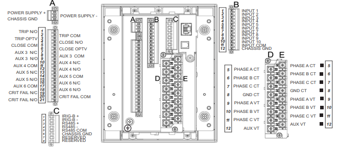
Use the following guidelines when selecting wires or lugs to connect to terminal blocks
A,B,C,D,E (Drawout case design), and terminal blocks D,E (Non-drawout case design):
• 12 AWG to 22 AWG (3.3 mm2 to 0.3 mm2): Single wire termination with/without
9.53 mm (0.375”) maximum diameter ring terminals (#8).
• 14 AWG to 22 AWG (2.1 mm2 to 0.3 mm2): Multiple wire termination with matching
wire sizes and stranding. Two wires maximum per circuit.
• 14 AWG to 22 AWG (2.1 mm2 to 0.3 mm2): Multiple wire termination with 9.53 mm
(0.375”) maximum diameter ring terminals (#8). Two ring terminals maximum per
circuit.
• Suggested wiring screw tightening torque, tighten to 12 in-lb (1.35 N-m).
• Minimum suggested temperature rating for the conductors is 75C.
Use the following guidelines when selecting wires to connect to terminal strip F (Drawout
case design), and terminal strips A,B,C (Non-drawout case design):
• 12 AWG to 24 AWG (3.3 mm2 to 0.2 mm2)
• Suggested wiring screw tightening torque: 4.5 in-lbs (0.5 N-m)
• The uncovered communications cable shield connected to the common terminal
should not exceed 1” (2.5 cm) for proper EMC shielding of the communications cable.
Phase sequence and transformer polarity
For correct operation of the relay features, the user must follow the instrument
transformer polarities, shown in the Typical Wiring Diagram. Note the solid square
markings shown with all instrument transformer connections. When the connections
adhere to this drawing, the arrow shows the direction of power flow for positive watts and
the positive direction of lagging vars.The phase sequence is user programmable for either
ABC or ACB rotation.
Current inputs
The 350 relay has four (4) channels for AC current inputs, each with an isolating
transformer. There are no internal ground connections on the current inputs. Current
transformers with 1 to 6000 A primaries may be used.
CAUTION: Verify that the relay’s nominal input current of 1 A or 5 A matches the secondary rating
of the connected CTs. Unmatched CTs may result in equipment damage or inadequate
protection.
CAUTION: IMPORTANT: The phase and ground current inputs will correctly measure up to 20
times the current input’s nominal rating. Time overcurrent curves become horizontal
lines for currents above the 20 × CT rating. This becomes apparent if the pickup level is
set above the nominal CT rating.
CAUTION: Before working on CTs, they MUST be short circuited.
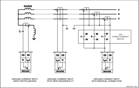
Ground and sensitive ground CT inputs
One dedicated ground input is referred to throughout this manual as the Ground Current
or Sensitive Ground Current input. Before making ground connections, consider that the
relay automatically calculates the neutral (residual) current from the sum of the three
phase current phasors. The following figures show three possible ground connections (or
three possible sensitive ground connections).
The ground input (Terminals D8 and E8) is used in conjunction with a Zero Sequence CT as
source, or in the neutral of wye-connected source CTs. The ground current input can be
used to polarize the neutral directional element. When using the residual connection set
the GROUND CT PRIMARY setpoint to a value equal to the PHASE CT PRIMARY setpoint.
In cases where the relay is equipped with sensitive ground CT (terminals D8 and E8) the
sensitive ground current input is intended for use either with a CT in a source neutral of a
high-impedance grounded system, or on ungrounded systems. On ungrounded systems it
is connected residually with the phase current inputs. In this case, the SENSTV GND CT
PRIMARY setpoint should be programmed to a value equal to the PHASE CT PRIMARY
setpoint. The sensitive ground current input can be connected to a Zero Sequence CT for
increased sensitivity and accuracy when physically possible in the system.
NOTE
NOTE: The Sensitive Ground input must only be used on systems where the maximum ground
current does not exceed current input specifications
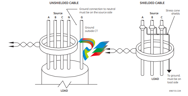
Zero sequence CT installation
The various CT connections and the exact placement of a Zero Sequence CT, for ground
fault current detection, are shown in the figure below. Twisted pair cabling on the Zero
Sequence CT is recommended.
Figure 2-35: Zero sequence core balance (CT) installation
Voltage inputs
The 350 relay has four channels for AC voltage inputs, each with an isolating transformer.
Voltage transformers up to a maximum 5000:1 ratio may be used. The nominal secondary
voltage must be in the 50 to 240 V range.The three phase inputs are designated as the “bus
voltage”. The Bus VT connections most commonly used, wye and delta (or open delta), are
shown in the typical wiring diagram.
NOTE
NOTE: If Delta VTs are used, the zero sequence voltage (V0) and neutral/sensitive ground
polarizing voltage (–V0) will be zero. Also, with the Delta VT connection, the phase-neutral
voltage cannot be measured and will not be displayed.
NOTE
NOTE: The 350 relay can be applied to both metering and protection feeders with up to 550 kV
phase-to-phase voltage. Please ensure that the selected VT ratio and VT secondary do not
result in a primary voltage exceeding 550 kV.
The single phase input is designated as the “Aux VT Input”. The Aux VT input channel can be
connected for either phase-neutral voltage Van, Vbn, Vcn, or for phase-phase voltage Vab,
Vbc, Vca as shown below.
Control power
CAUTION: Control power supplied to the relay must match the installed power supply range. If the
applied voltage does not match, damage to the unit may occur. All grounds MUST be
connected for safe, normal operation regardless of control power supply type.
The label found on the relay specifies its order code or model number. The installed power
supply’s operating range will be one of the following:
LO: 24 to 48 V DC (Range: 20 to 60 V DC)
HI: 125 to 250 V DC/120 to 240 V AC (Range: 84 to 250 V DC/60 to 300 V AC (50 and 60
Hz))
CAUTION: The relay should be connected directly to the ground bus, using the shortest practical
path. A tinned copper, braided, shielding and bonding cable should be used. As a
minimum, 96 strands of number 34 AWG should be used. Belden catalog number 8660
is suitable.
CAUTION: Isolate power prior to servicing.
An external switch, circuit breaker, or other protective device must be connected near to
the equipment
Contact inputs
External contacts can be connected to the relay’s ten (10) digital inputs. These contacts are
wet only.
The inputs can be programmed to different thresholds depending on the DC voltage (17,
33, 84, 166).
CAUTION: Ensure correct polarity on contact input connections and do not connect any contact
input circuits to ground or else relay hardware may be damaged.
A wet contact has one side connected to the positive terminal of an external DC power
supply. The other side of this contact is connected to the required contact input terminal. In
addition, the negative side of the external source must be connected to the relay’s DC
negative rail at Terminal C11. The maximum external source voltage for this arrangement
is 300 V DC.
Trip and Close output relays
The 350 relay is equipped with seven electromechanical output relays: two special relays
designed for Breaker trip and close (Relay 1 “Trip”, Relay 2 “Close”), four general purpose
relays (Auxiliary Relays 3 to 6), and a Critical Failure relay. The special purpose relays have
fixed operating characteristics and the general purpose relays can be configured by the
user.
Operation of the Trip and Close output relays is designed to be controlled by the state of
the circuit breaker as monitored by a 52a or 52b contact.
• The Trip and Close relays reset after the breaker is detected in a state corresponding
to the command. When a relay feature sends a command to one of these special
relays, it will remain operational until the requested change of breaker state is
confirmed by a breaker auxiliary contact and the initiating condition has reset.
• If the initiating feature resets, but the breaker does not change state, the output relay
will be reset after a default interval of 2 seconds.
• If neither of the breaker auxiliary contacts, 52a nor 52b, is programmed to a contact
input, the Trip Relay is de-energized after either the delay programmed in the Breaker
Failure feature, or a default interval of 100 ms after the initiating input resets. The
Close Relay is de-energized after 200 ms.
• If a delay is programmed for the Trip or Close contact seal-in time, then this delay is
added to the reset time. Note that the default setting for the seal-in time is 40 ms.
Breaker monitoring (Trip and Close coil monitoring) is performed by a built-in voltage
monitor on Form A output relays: #1 Trip, and #2 Close. The voltage monitor is connected
across each of the two Form A contacts, and the relay effectively detects healthy current
through the circuit. In order to do this, an external jumper must be connected between
terminals A2 and A3 for Trip coil monitoring, or/and B4, and B5 for Close coil monitoring.
As long as the current through the Voltage Monitor is above the threshold of the trickle
currents (see Technical Specification for Form A output relays), the circuit integrity for the
Trip (Close) coil is effectively normal. If the Trip (Close) coil circuit gets disconnected, or if in
general a high resistance is detected in the circuitry, a Trip (Close) alarm will be set and the
“ALARM” and “MAINTENANCE” LEDs will be on.
Example 1: The figures below show the two different connections of the breaker trip (close)
coil to the relay’s trip output #1 terminals (output #2 Close coil monitoring) for both no
voltage monitoring and voltage monitoring of the trip (close) circuit integrity.
NOTE
NOTE: To monitor the trip coil circuit integrity, use the relay terminals A2 and B3 to connect the
Trip coil, and provide a jumper between terminals A2 (optional voltage) and A3.
IRIG-B
IRIG-B is a standard time code format that allows time stamping of events to be
synchronized among connected devices within 1 millisecond. The IRIG time code formats
are serial, width-modulated codes which can be either DC level shift or amplitude
modulated (AM) form. The type of form is auto-detected by the 350 relay. Third party
equipment is available for generating the IRIG-B signal; this equipment may use a GPS
satellite system to obtain the time reference so that devices at different geographic
locations can also be synchronized.
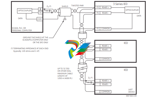
The uncovered communications cable shield connected to the common terminal should
not exceed 1” (2.5 cm) for proper EMC shielding of the communications cable.
350 Feeder Protection System
Chapter 3: Interfaces
Interfaces
There are two methods of interfacing with the 350 Feeder Protection System.
• Interfacing via the relay keypad and display.
• Interfacing via the EnerVista 3 Series Setup software.
This section provides an overview of the interfacing methods available with the 350 using
the relay control panels and EnerVista 3 Series Setup software. For additional details on
interface parameters (for example, settings, actual values, etc.), refer to the individual
chapters.
-
 Beckhoff PLC module CX1020-0000 Basic CPU module (service phase)
 -
 Beckhoff CP7812-1056-0010 15" Multitouch Display Control Panel
 -
 Beckhoff CX5120-0115 /2GB Controller Module
 -
 Beckhoff CP7201-1000-0000 Industrial Panel PC
 -
 Beckhoff Servo Motor AM8061-0JH1-0000
 -
 BECKHOFF CP6503-0001-0050 Built-in Panel PC
 -
 Beckhoff CP3919-0010 Display G190ETN01.2 19" PCT V04. Multi-touch Control Panel
 -
 Beckhoff CX5110-0112-9020/000368201 Embedded PC Intel Atom Processor
 -
 Beckhoff AX8206-0000 Dual-Axis Module
 -
Beckhoff Nail Operating Terminal CP7032-1031-0010
-
Beckhoff AM8042-0EH1-0000 Servomotor 4.10 Nm (M0), F4 (87 mm)
-
 Beckhoff EK9300 Beckhoff CPU Module
 -
Beckhoff CP3224-0020 Multitouch-Panel-PC
-
 Beckhoff CP2712-0000 12.1" 24VDC Touch Screen WMD0
 -
 BECKHOFF CX5240-0195 / 0000289234 Embedded PC 40 GB CFast Card
 -
 Beckhoff CP6932-1000-0000 Control Panel
 -
 BECKHOFF CX5120-0121 PLC Module
 -
 Beckhoff EL3218 | EtherCAT Terminal, 8-channel analog input
 -
 Beckhoff C6640-0050 | Control cabinet Industrial PC
 -
 Beckhoff Cx5130-0120/4GB Embedded-PC
 -
 BECKHOFF CX2030-0122 PLC PROCESSOR
 -
 BECKHOFF CX5020-0122 Controller Module
 -
 Beckhoff CP3915-0000 Multitouch Panel
 -
 BECKHOFF EL3014 | EtherCAT Terminal
 -
 BECKHOFF Industrial Computer c6920-1057-0030
 -
 Beckhoff CX5130-0141/4GB CX5130-0141 Embedded PC
 -
 Beckhoff C6240-1052-0040 4-086-06-3073 Industrial Computer
 -
 Beckhoff CX5140-0135 /4GB High-Performance Embedded Industrial PC
 -
 Beckhoff C6515-1001-0000 Industrial PC
 -
 Beckhoff AX5103-0000-0200 - Digital Compact Servo Drives
 -
 Beckhoff CX2030-0130-1003/4GB Basic CPU module
 -
 Beckhoff AX8620-0000 Power Supply Module
 -
 Beckhoff CX9020-0111 module with
 -
 Beckhoff EL7332 PLC Module
 -
 BECKHOFF CP7709-0001-0020 HMI
 -
 Beckhoff CX5120-0155/2GB Embedded PC
 -
 BECKHOFF CP7037-1037-0010 OPERATOR INTERFACE TOUCHSCREEN
 -
 Beckhoff EK9000 | ModbusTCP/UDP Bus Coupler
 -
 Beckhoff Touch Panel Screen CP6020 -0000-0000
 -
 Beckhoff CX2020-0121 Module FAST Shipping
 -
 Beckhoff CX2030-0125 Basic CPU Module
 -
 Beckhoff CP3918-0000 Multi-Touch 18.5" Control Panel
 -
 Automotion LC4A00010 DC BL Motor Control, ATS, Sub Assy, SCP, 115VAC,
 -
 500T-115VAC - VAS ENGINEERING - DORIC 500 SERIES DIGITAL TEMP INDICATOR
 -
 Honeywell X-DCS2000/EN Digital Integrated System Manager 50/60Hz 100-240V #4
 -
 Kollmorgen S60600 Servostar600 606-Fan 4 kVA, 6 A, 3 X 230 - 480 V
 -
 ABB XZ C828 A101 Didt Dioder Snubber 3BHE039453R0101
 -
 ABB 3BHB027232R0001 1-Phase Charging Transformer
 -
 ABB 3BHE006412R0101 Circuit Board UFC762AE101
 -
 ABB XVC770BE101 3BHE021083R0101 Circuit Board
 -
 ABB 3BHE021887R0101 (Model: UBCC717BE101 / UBC717BE101) is an advanced
 -
 ABB 3BHE032593R0001 Isolated Power Supply
 -
 ABB 3BSC610023R0001 POWER SUPPLY SD812
 -
 Beckhoff C6650-0060 | Control cabinet Industrial PC
 -
 Beckhoff CP2916-0000 Industrial HMI Display Panel
 -
 Beckhoff AM8053-0L2B-0000 Servomotor 15.4 Nm (M0), F5 (104 mm)
 -
 Beckhoff CP6202-0001-0020 Industrial Panel PC
 -
Beckhoff CX2020-0120 Plc Module
-
 Beckhoff CX1010-0111 BASIC CPU MODULE
 -
 Beckhoff C6017-0010 | Ultra-compact Industrial PC
 -
 BECKHOFF CX2040-0155 Plc Module
 -
 Beckhoff CX5120-0125 Embedded PC
 -
 BECKHOFF C6930-0040 INDUSTRIAL CONTROL COMPUTER
 -
 Beckhoff CP6907-0001-0000 Economy Built-in Control Panel
 -
 Beckhoff CP2912-0000 Multi-Touch Built-In Control Panel
 -
 Beckhoff C6015-0010 Ultra-Compact Industrial PC
 -
 Beckhoff CX5130 | Embedded PC with Intel Atom® E3827
 -
 Beckhoff C6030-0060 Ultra-Compact Industrial PC
 -
 OMRON 3G3XV-A2007 3G3XV-A2007-NEV2
 -
 Omron NJ1019000 NJ1 programable logic controller
 -
 OMRON C120-LK202-EV1/C120LK202EV1
 -
 OMRON C200H-AD003 PLC
 -
 OMRON C200H-CPU23-E COIL 24VDC PLC
 -
 Omron C200HG - C200H-ID212- C200H-OC226 C200HW-BC101 PLC Base Unit
 -
 OMRON C200H-OC222(Output Unit),C200H-PS211(Power Supply Unit),SP001 Module Rack
 -
 OMRON C200H-RT201 PROGRAMMABLE CONTROLLER
 -
 OMRON C200HS-CPU01-E SYSMAC PROGRAMMABLE CONTROLLER
 -
 OMRON C200H-SNT31 C200H Programmable Controllers
 -
 OMRON C200HW-MC402-E Motion control unit
 -
 OMRON C200PC-ISA02-DRM-E PLC ISA bus compatible board card
 -
 OMRON C500-CT012 PLC
 -
 OMRON C500-NC103-E PLC
 -
 OMRON C500-NC222-E PLC
 -
 OMRON C500-PRW05-V1 PLC
 -
 OMRON C500-PRW06 PROGRAMMABLE CONTROLLER
 -
 OMRON C500-PS223-E 3G2A5-PS223-E PLC SYSMAC PROGRAMMABLE CONTROLLER
 -
 OMRON C500-TU001 3G2A5-TU001 PLC PLC
 -
 OMRON C60H-C1DR-DE-V1 Programmable Controllers
 -
 OMRON C60H-C5DR-DE-V1 Programmable Controllers
 -
 OMRON C60H-C6DR-DE-V1 Programmable Controllers
 -
 OMRON CJ1G-CPU44H CPU module
 -
 OMRON CJ1G-CPU45H PLC
 -
 OMRON CJ1M-CPU13-ETN V4.0 PLC PLC
 -
 OMRON CJ1W-AD041-V1 Analog input uni
 -
 OMRON CJ1W-CORT21 PLC module
 -
 OMRON CJ1W-IDP01 Input unit
 -
 OMRON CJ1W-MCH71 - MECHATROLINK-II
 -
 OMRON CJ1W-MD261 Digital I/O
 -
 OMRON CJ1W-NC413 Position control unit
 -
 OMRON CJ1W-NCF71 Position Control Units
 -
 OMRON CJ1W-PTS51 Process Simulation I/O Module
 -
 OMRON CJ1W-PTS52 Process Simulation I/O Module
 -
 OMRON CJ1W-SCU21-V1 PLC
 -
 Omron CJ1W-SCU22 Serial Communication Unit
 -
 OMRON CJ1W-TC001 CJ Series Temperature Control Unit
 -
 Omron CK3W-AX1515N Motion Controller
 -
 Omron CP1E-N60DR-D Compact PLC CPU
 -
 OMRON CP1E-NA20DT1-D PLC PLC
 -
 OMRON CP1H-X40DT-D plc PLC
 -
 OMRON CPM2C-S110C-DRT Interface module
 -
 OMRON CQM1-AD041 PLC
 -
 SAACKE F‑GDSA‑1 / F‑GDSA‑2 Feuerungsautomaten
 -
 SAACKE F-GDSA 143303 Controller SHIPS UPS
 -
 ICS Triplex T8270 Trusted 24 Vdc FanAssembly
 -
 SCHNEIDER M522220000 SA SM_DO16R 16 DIGITAL OUTPUTS MODULE
 -
 LENZ EPL10200-W EPZ-10203 CANPT010W3E
 -
 OMRON CQM1H-ADB21 PLC
 -
OMRON CQM1H-CPU61 PLC
-
 OMRON CQM1H-MAB42 PLC
 -
 OMRON CQM1-TC102 CQM1-TC101 PLC
 -
 OMRON CS1G-CPU44-EV1 PLC
 -
 OMRON CS1G-CPU44H CPU
 -
OMRON CS1H-CPU63-EV1 PLC
-
 OMRON CS1H-CPU66-V1 PLC
 -
 OMRON CS1W-CLK13 PLC communication module
 -
OMRON CS1W-EIP21 PLC
-
 OMRON CS1W-MAD44 PLC PLC
 -
 OMRON CS1W-SCU31-V1 CVM1-BC103 PLC


