
HarmonicHarmonic Drive™ servo
Read this manual thoroughly before designing the application, installation, maintenance or inspection of the actuator.
Indicates a potentially hazardous situation,
which, if not avoided, could result in death
or serious personal injury.
Indicates a potentially hazardous situation, which, if
not avoided, may result in minor or moderate personal
injury and/or damage to the equipment.
LIMITATION OF APPLICATIONS:
The equipment listed in this document may not be used for the applications listed below:
¨ Space equipment ¨ Automobile, automotive parts
¨ Aircraft, aeronautic equipment ¨ Amusement equipment, sport equipment, game machines
¨ Nuclear equipment ¨ Machine or devices acting directly on the human body
¨ Household apparatus ¨ Instruments or devices to transport or carry people
¨ Vacuum equipment ¨ Apparatus or devices used in special environments
If the above list includes your intending application for our products, please consult us.
Safety measures are essential to prevent accidents resulting in death, injury or damage of the equipment due to
malfunction or faulty operation.
CAUTIONS FOR ACTUATORS AT APPLICATION DESIGNING
Always use under followings conditions:
-Ambient temperature: 0℃ to 40℃
-Ambient humidity: 20% to 80%RH (Non-condensation)
-Vibration: Max 24.5 m/S2
-No contamination by water, oil
-No corrosive or explosive gas
Follow exactly the instructions in the relating
manuals to install the actuator in the equipment.
-Ensure exact alignment of motor shaft center and
corresponding center in the application.
Failure to observe this caution may lead to vibration,
resulting in damage of output elements.
CAUTION FOR ACTUATORS IN OPERATIONS
Keep limited torques of the actuator.
-Keep limited torques of the actuator.
-Be aware, that if arms attached to output element hits
by accident an solid, the output element may be
uncontrollable.
Never connect cables directly to a power supply
socket.
-Each actuator must be operated with a proper driver.
-Failure to observe this caution may lead to injury, fire or
damage of the actuator.
Do not apply impacts and shocks
-Do not use a hammer during installation
-Failure to observe this caution could damage the
encoder and may cause uncontrollable operation.
Avoid handling of actuators by cables.
-Failure to observe this caution may damage the wiring,
causing uncontrollable or faulty operation.
CAUTIONS FOR DRIVERS AT APPLICATION DESIGNING
Always use drivers under followings conditions:
-Mount in a vertical position keeping sufficient distance
to other devices to let heat generated by the driver
radiate freely.
-Ambient temperature: 0℃ to 50℃
-Ambient humidity: less than 95% RH (Non
condensation)
-No contamination by water, oil or foreign matters
-No corrosive, inflammable or explosive gas
Use sufficient noise suppressing means and safe
grounding.
-Keep signal and power leads separated.
-Keep leads as short as possible.
-Ground actuator and driver at one single point, minimum
ground resistance class: D (less than 100 ohms)
-Do not use a power line filter in the motor circuit.
Pay attention to negative torque by inverse load.
–Inverse load may cause damages of drivers.
-Please consult our sales office, if you intent to apply
products for inverse load.
Use a fast-response type ground-fault detector
designed for PWM inverters.
-Do not use a time-delay -type ground-fault detector.
CAUTION FOR DRIVERS IN OPERATIONS
Never change wiring while power is active.
-Make sure of power non-active before servicing the
products.
-Failure to observe this caution may result in electric
shock or personal injury.
Do not touch terminals or inspect products at least
5 minutes after turning OFF power.
-Otherwise residual electric charges may resul t in
electric shock.
-Make installation of products not easy to touch their
inner electric components.
Do not make a voltage resistance test.
-Failure to observe this caution may result in damage of
the control unit.
-Please consult our sales office, if you intent to make a
voltage resistance test.
Do not operate control units by means of power
ON/OFF switching.
-Start/stop operation should be performed via input
signals.
Failure to observe this caution may result in deterioration
of electronic parts.
DISPOSAL OF AN ACTUATOR, A MOTOR, A CONTROL UNIT AND/OR THEIR PARTS
All products or parts have to be disposed of as industrial waste.
-Since the case or the box of drivers have a material indication, classify parts and dispose them separately.
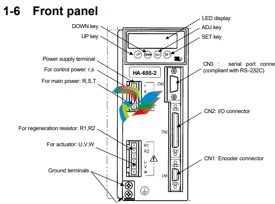
Functions
◆ LED display
Indicates operating states of the HA-655 driver, parameters, alarms, by a 6-digit 7segment-LED.
◆ Keys labeled [UP], [DOWN], [ADJ], and [SET]
Are used for changing indications, setting and tuning functional parameters, and operating an actuator
manually in a JOG mode.
◆ CN1: encoder connector
Accepts a connector of an encoder cable form an actuator.
◆ CN2: I/O connector
Accepts I/O signals to/from a host device.
◆ CN3: Serial port connector (compliant with RS-232C)
Is connected to a PC with a dedicated cable. You can monitor, set, and tune parameters on the PC’s
-
 CTI 2500-ADP2-DISC Discrete Wiring Adapter for Series 500
 -
 CTI 2500-ADP1 Analog Wiring Adapter for Series 500
 -
 CTI 2500C-RADP-RS485 Remote Base Controller Adapter for Series 500
 -
 CTI 2500C-RADP-RBC Profibus RBC Adapter for Series 500
 -
 CTI 2500C-PADP-120V 120VAC 50W Power Supply for Series 500
 -
 CTI 2500-RADP RBC Adapter for Series 500
 -
 CTI 2500-R4500 520/530/DBC Adapter for Series 500 - MATURE
 -
 CTI 2500-PADP Power Supply Adapter for Series 500
 -
 CTI 2500-IADP I/O Adapter for Series 500
 -
 CTI 2500-VP15A-N4-W7 15" Flat-Panel PC with Windows® 7 Embedded
 -
 CTI 2500S-27-1750 Slice I/O, Ethernet, RS232/485. 900MHz, 2DIO / 4UAI / 2AI
 -
 CTI 2500S-26-1750 Slice I/O, Ethernet, RS232/485. 900MHz, 8DIO / 2UAI
 -
 CTI 2500S-23-1750 Slice I/O, Ethernet, RS232/485. 900MHz, 4DI / 4DO / 2UAI / 2AO
 -
 CTI 2500S-27-1550 Slice I/O, RS232/485. 2DIO / 4UAI / 2AI
 -
 CTI 2500S-26-1550 Slice I/O, RS232/485. 8DIO / 2UAI
 -
 CTI 2500S-23-1550 Slice I/O, RS232/485. 4DI / 4DO / 2UAI / 2AO
 -
 CTI 2500S-27-1050 Slice I/O, Ethernet, 2DIO / 4UAI / 2AI
 -
 CTI 2500S-26-1050 Slice I/O, Ethernet, 8DIO / 2UAI
 -
 CTI 2500S-23-1050 Slice I/O, Ethernet, 4DI / 4DO / 2UAI / 2AO
 -
 CTI 2500C-32F-CJC 32-Pin Field Wiring Connector with Cold Junction Compensation
 -
 CTI 2500C-32F 32-Pin Field Wiring Connector
 -
 CTI 2500C-8-TC Eight Thermocouple Inputs
 -
 CTI 2500C-8-RTD Eight RTD Inputs
 -
 CTI 2500C-8-RL-FC 8 Form-C Relay Outputs
 -
 CTI 2500C-8-IDO-24V 8 Isolated 24VDC Outputs
 -
 CTI 2500C-8-IDO-120V 8 Isolated 120VAC Outputs
 -
 CTI 2500C-16-DO-24V Sixteen 24VDC Digital Outputs
 -
 CTI 2500C-16-DO-120V Sixteen 120VAC Digital Outputs
 -
.png) CTI 500C-16-IDI-24V Sixteen Isolated 24V AC/DC Digital Inputs
CTI 500C-16-IDI-24V Sixteen Isolated 24V AC/DC Digital Inputs -
 CTI 2500C-16-IDI-120V Sixteen Isolated 120V AC/DC Digital Inputs
 -
 CTI 2500C-16-DIDO-SIM Sixteen Digital Input and Output SImulator
 -
 CTI 2500C-16-DI-24V Sixteen 24V AC/DC Digital Inputs
 -
 CTI 2500C-16-DI-120V Sixteen 120V AC/DC Digital Inputs
 -
 CTI 2500C-RBC-RS485 RS485 Remote Base Controller
 -
 CTI 2500C-RBC-PRF Profibus Remote Base Controller
 -
 CTI 2500C-PS-24V-35 35-Watt DC Power Supply
 -
 CTI 2500C-PS-120V-35 35-Watt AC Power Supply
 -
 CTI 2500C-R8 Eight-Slot Base
 -
 CTI 2500C-R4 Four-Slot Base
 -
 CTI 2500C-R16 Sixteen-Slot Base
 -
 CTI 2500C-2572-B Fast Ethernet TCP/IP Adapter
 -
 CTI 2500C-J750 Compact Janus PAC with 3MB Project Memory
 -
 CTI 2500C-C300 CPU with 512K User Memory
 -
 CTI 2500C-C200 CPU with 256K User Memory
 -
 CTI 2500C-C100 CPU with 128K User Memory
 -
 CTI 2500C-8-AO 8 Analog Outputs
 -
 CTI 2500C-8-AI 8 Analog Inputs
 -
 CTI 2559-FCAL Precision Calibration Connector
 -
 CTI 2559-FPC 40-Position Screw-Terminal Connector
 -
 CTI 2500-RFC PLC to RF Modem Cable
 -
 CTI 2500-40F 40-Position Standard Screw-Terminal Connector
 -
 CTI 2505 Vibration Sensor Interface Module
 -
 CTI 2554-A 4-Channel Isolated High Speed Counter Module
 -
 CTI 2553-A 2-Channel Mag Meter Input Module
 -
 CTI 2502 2-Channel High Speed Counter Input Module
 -
 CTI 2559-TC 8-Channel Thermocouple Input Module
 -
 CTI 2556-A 16-Channel Isolated Thermocouple Input Module
 -
 CTI 2556 16-Channel Isolated Thermocouple Input Module
 -
 CTI 2551-A 8-Channel Isolated Thermocouple Input Module
 -
 CTI 2559-RTD 8-Channel RTD Input Module
 -
 CTI 2557-A 16-Channel RTD Input Module
 -
 CTI 2557 16-Channel RTD Input Module
 -
 CTI 2552-A 8-Channel Isolated RTD Input Module
 -
 CTI 2534 8-Point Form-C Relay Output Module
 -
 CTI 2532 16-Point Form-A Relay Output Module
 -
 CTI 2531 32-Point Form-A Relay Output Module
 -
 CTI 2530 8-Point Form-C Relay Output Module
 -
 CTI 2562 8-Channel Analog Output Module
 -
 CTI 2560-A 8-Channel Isolated Analog Output Module
 -
 CTI 2501 8in/4out Analog Module
 -
 CTI 2558 8-Channel Analog Input Module
 -
 CTI 2555-A 16-Channel Analog Input Module
 -
 CTI 2550-A 8-Channel Isolated Analog Input Module
 -
 CTI 2599 8/16/32-Point AC Output Module
 -
 CTI 2598-8 8-Point AC Output Module
 -
 CTI 2598 8/16-Point AC Output Module
 -
 CTI 2597 8/16/32-Point DC Output Module
 -
 CTI 2596-8 8-Point DC Output Module
 -
 CTI 2596 8/16-Point DC Output Module
 -
 CTI 2595 16-Point TTL/Word Output Module
 -
 CTI 2591-EF 16-Point Isolated 11-146 VDC Output with Front Panel Accessible Fuses
 -
 CTI 2591-A 16-Point Isolated 11-146 VDC Output Module
 -
 CTI 2590-EF 16-Point Isolated 20-132 VAC Output with Front Panel Accessible Fuses
 -
 CTI 2590-A 16-Point Isolated Discrete 20-132 VAC Output Module
 -
 CTI 2589-B 8/16/32-Point Universal Discrete Input Module
 -
 CTI 2589-A 8/16/32-Point Universal Discrete Input Module
 -
 CTI 2588-8 8-Point Universal Discrete Input Module
 -
 CTI 2585 16-Point TTL/Word Input Module
 -
 CTI 2582 16-Point Isolated 125 VDC Input Module
 -
 CTI 2581 16-Point Isolated 12-56 VDC Input Module
 -
 CTI 2580 16-Point Isolated 95-132 VAC Input Module
 -
 CTI 2500-TAP RS485 Network Tap
 -
 CTI 2500-RIO-B RS485 Remote Base Controller
 -
 CTI 2500-RIO-A RS485 Remote Base Controller
 -
 CTI 2500-RBC Profibus Remote Base Controller
 -
 CTI 2515-A 100-Watt AC/DC Power Supply with Redundancy Support
 -
 CTI 2515 100-Watt AC Power Supply (MATURE - replaced by 2515-A)
 -
 CTI 2513-A 75-Watt DC Power Supply with Redundancy Support
 -
 CTI 2513 75-Watt 24VDC Power Supply
 -
 CTI 2512-A 75-Watt AC/DC Power Supply with Redundancy Support
 -
 CTI 2512 75-Watt AC/DC Power Supply
 -
 CTI 2510 125 VDC Power Supply
 -
 CTI 2500-SSB Single Slot Blank Front Panel
 -
 CTI 2500-R11-A Eleven-Slot Redundant Base
 -
 CTI 2500P-R16 Sixteen-Slot Base with High-Speed Channel
 -
 CTI 2500P-R8 Eight-Slot Base with High-Speed Channel
 -
 CTI 2500P-R4 Four-Slot Base with High-Speed Channel
 -
 CTI 2541 Redundant Processor Manager Module
 -
 CTI 2577 Profibus DP Slave Adapter
 -
 CTI 2573-MOD Serial Interface Adapter with MODBUS
 -
 CTI 2572-AF Fast Ethernet TCP/IP Adapter with Optical Fiber Connection
 -
 CTI 2572-A Fast Ethernet TCP/IP Adapter
 -
 CTI 2572 Ethernet TCP/IP Adapter
 -
 CTI 2572-B Fast Ethernet TCP/IP Adapter
 -
 CTI 2576 DeviceNet™ Scanner Module (MATURE)
 -
 CTI 2500P-ECC1 Ethernet Communications Coprocessor
 -
 CTI 2500P-JACP Janus Application Coprocessor
 -
 CTI 2500P-ACP1 Application Coprocessor (MATURE - replaced by 2500P-JACP)
 -
 CTI 2500P-J450 Janus PAC with 2MB Project Memory
 -
 CTI 2500-C400 CPU with 3072K User Memory
 -
 CTI 2500-C300 CPU with 512K User Memory
 -
 CTI 2500-C200 CPU with 256K User Memory
 -
 CTI 2500-C100 CPU with 128K User Memory
 -
 CTI 2500P-J750 Janus PAC with 3MB Project Memory
 -
 Shinkawa WHF3006M Displacement Converter
 -
Shinkawa JBP-220 (P-24-94A / P-24-94B) Circuit Board Module
-
 SHINKAWA WKN-142K5 2-WIRE VIBRATION TRANSDUCER
 -
Shinkawa FRP-321 (P-26-54A / P-26-54B) Circuit Board Module


