
HarmonicHarmonic Drive™ servo
and at power supply after disconnecting the cable between the driver and the encoder for a long duration.
To recover the alarm, input the multi-turn data clear signal at least 4 seconds, and shut off the control
power once and turn it on again.
◆ ABS MTD overflow (54)
For the absolute encoder, the alarm occurs when the count for multi-turn data (MTD) goes beyond the
range of +4095 to - 4096 turns (motor axis). To recover the alarm, input the multi-turn data clear signal at
least 4 seconds, and shut off the control power once and turn it on again.
◆ ABS multi-turn data error (55)
For the absolute encoder, during an energy-saving mode, where no power by power supply but the
encoder circuit is active only by the power of a built-in condenser and a built-in battery, the alarm occurs
when the encoder rotates too fast at the acceleration rate and speed exceeding the recording ability of
the multi-turn counter on the mode. To recover the alarm, input the multi-turn data clear signal at least 4
seconds, and shut off the control power once and turn it on again.
◆ ABS low battery voltage (56)
For the absolute encoder, when voltage of the built-in battery is low. To recover the alarm, change the
battery for a new one, and shut off the control power once and turn it on again.
◆ ABS send data rule error (57)
The absolute encoder rotates more than 127 resolvable pulses by external torque during transmitting
absolute data. To recover the alarm, shut off the control power once and turn it on again.
◆ Error counter overflow (60)
The alarm occurs when an error count exceeds the set value in [parameter mode]→[6: position error
allowance]. It is possible to clear the alarm by inputting a signal to [CN2-2 clear: CLEAR]. The error
count is cleared at the same time.
◆ Memory failure (RAM) (70)
The alarm occurs when the driver’s RAM memory fails. It is impossible to clear the alarm.
◆ Memory failure (EEPROM) (71)
The alarm occurs when the driver’s EEROM memory fails. It is impossible to clear the alarm.
◆ CPU failure (76)
The alarm occurs when the driver’s CPU fails. It is impossible to clear the alarm.
Chapter 2 Functions
2-1 Control system of the HA-655 driver
It is said that [plan, do, see] is essential to perform perfect
jobs. In other words, the [plan, do, see] is the repeating
cycle of command→action→result→feedback→modified
command → action → feedback →・・・・ .
Driving machines precisely requires the same control as
the above job cycle, that is [Motion command→run→
feedback→modified command→・・・・].
For example, assume the required motion is rotation to a
target angle and stopping there. To perform the motion,
the motor must be equipped with an angular sensor to
detect a current position, and the position data must be
compared with the command. If the position data is
different than the command, the motor rotates until the
position data becomes equal to the command. This is an
example of a position servo system.
The speed control system is the same. The motor is
equipped with a speed sensor and the speed is compared
with the speed command. If the speed is different from the
command, the motor accelerates or decelerates until the
motor speed becomes equal to the command. This is an
example of the speed servo system.
The HA-655 driver realizes above both controls of position and speed with the same unit.
The fundamental configuration of servo system of the HA-655 driver is as follows:
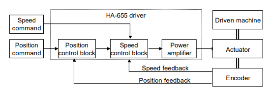
The HA-655 driver function is consists of three parts: the position control block, the speed control block,
and the power amplifier.
In the position mode, a command position from a host is compared to a feedback position. If there is a
difference between them, the position control block commands the power amplifier through the speed
control block to flow current to the actuator until there is no difference.
In the speed mode, a speed command is directly inputted to the speed control block. The speed block
compares the command and current feedback speed. If there is a difference between them, the speed
control block commands to the power amplifier flow the current to the actuator until there is no
difference.
The HA-655 driver allows two types of encoder as a functional member of the feedback system,
optionally: an incremental encoder or an absolute encoder.
2-2 Position mode
The HA-655 driver makes use of either the position control or the speed control. This section describes
the position mode. (※ The default setting is the [position mode].)
Before driving, set the control mode by [parameter mode] → [0: control mode].
2-2-1 Command configuration in position mode
In the position mode, the command is transmitted from a host in the form of a digital pulse signal train.
The HA-655 driver provides two pair of two ports (CN2-27&28, CN2-29&30) for the command pulses.
Signals of three type of configurations are available for the ports.
● Setting a command configuration
[Parameter mode]→[1: command configuration]
● Relating I/O pins
Input pins: CN2-26 to 30
-
 Beckhoff PLC module CX1020-0000 Basic CPU module (service phase)
 -
 Beckhoff CP7812-1056-0010 15" Multitouch Display Control Panel
 -
 Beckhoff CX5120-0115 /2GB Controller Module
 -
 Beckhoff CP7201-1000-0000 Industrial Panel PC
 -
 Beckhoff Servo Motor AM8061-0JH1-0000
 -
 BECKHOFF CP6503-0001-0050 Built-in Panel PC
 -
 Beckhoff CP3919-0010 Display G190ETN01.2 19" PCT V04. Multi-touch Control Panel
 -
 Beckhoff CX5110-0112-9020/000368201 Embedded PC Intel Atom Processor
 -
 Beckhoff AX8206-0000 Dual-Axis Module
 -
Beckhoff Nail Operating Terminal CP7032-1031-0010
-
Beckhoff AM8042-0EH1-0000 Servomotor 4.10 Nm (M0), F4 (87 mm)
-
 Beckhoff EK9300 Beckhoff CPU Module
 -
Beckhoff CP3224-0020 Multitouch-Panel-PC
-
 Beckhoff CP2712-0000 12.1" 24VDC Touch Screen WMD0
 -
 BECKHOFF CX5240-0195 / 0000289234 Embedded PC 40 GB CFast Card
 -
 Beckhoff CP6932-1000-0000 Control Panel
 -
 BECKHOFF CX5120-0121 PLC Module
 -
 Beckhoff EL3218 | EtherCAT Terminal, 8-channel analog input
 -
 Beckhoff C6640-0050 | Control cabinet Industrial PC
 -
 Beckhoff Cx5130-0120/4GB Embedded-PC
 -
 BECKHOFF CX2030-0122 PLC PROCESSOR
 -
 BECKHOFF CX5020-0122 Controller Module
 -
 Beckhoff CP3915-0000 Multitouch Panel
 -
 BECKHOFF EL3014 | EtherCAT Terminal
 -
 BECKHOFF Industrial Computer c6920-1057-0030
 -
 Beckhoff CX5130-0141/4GB CX5130-0141 Embedded PC
 -
 Beckhoff C6240-1052-0040 4-086-06-3073 Industrial Computer
 -
 Beckhoff CX5140-0135 /4GB High-Performance Embedded Industrial PC
 -
 Beckhoff C6515-1001-0000 Industrial PC
 -
 Beckhoff AX5103-0000-0200 - Digital Compact Servo Drives
 -
 Beckhoff CX2030-0130-1003/4GB Basic CPU module
 -
 Beckhoff AX8620-0000 Power Supply Module
 -
 Beckhoff CX9020-0111 module with
 -
 Beckhoff EL7332 PLC Module
 -
 BECKHOFF CP7709-0001-0020 HMI
 -
 Beckhoff CX5120-0155/2GB Embedded PC
 -
 BECKHOFF CP7037-1037-0010 OPERATOR INTERFACE TOUCHSCREEN
 -
 Beckhoff EK9000 | ModbusTCP/UDP Bus Coupler
 -
 Beckhoff Touch Panel Screen CP6020 -0000-0000
 -
 Beckhoff CX2020-0121 Module FAST Shipping
 -
 Beckhoff CX2030-0125 Basic CPU Module
 -
 Beckhoff CP3918-0000 Multi-Touch 18.5" Control Panel
 -
 Automotion LC4A00010 DC BL Motor Control, ATS, Sub Assy, SCP, 115VAC,
 -
 500T-115VAC - VAS ENGINEERING - DORIC 500 SERIES DIGITAL TEMP INDICATOR
 -
 Honeywell X-DCS2000/EN Digital Integrated System Manager 50/60Hz 100-240V #4
 -
 Kollmorgen S60600 Servostar600 606-Fan 4 kVA, 6 A, 3 X 230 - 480 V
 -
 ABB XZ C828 A101 Didt Dioder Snubber 3BHE039453R0101
 -
 ABB 3BHB027232R0001 1-Phase Charging Transformer
 -
 ABB 3BHE006412R0101 Circuit Board UFC762AE101
 -
 ABB XVC770BE101 3BHE021083R0101 Circuit Board
 -
 ABB 3BHE021887R0101 (Model: UBCC717BE101 / UBC717BE101) is an advanced
 -
 ABB 3BHE032593R0001 Isolated Power Supply
 -
 ABB 3BSC610023R0001 POWER SUPPLY SD812
 -
 Beckhoff C6650-0060 | Control cabinet Industrial PC
 -
 Beckhoff CP2916-0000 Industrial HMI Display Panel
 -
 Beckhoff AM8053-0L2B-0000 Servomotor 15.4 Nm (M0), F5 (104 mm)
 -
 Beckhoff CP6202-0001-0020 Industrial Panel PC
 -
Beckhoff CX2020-0120 Plc Module
-
 Beckhoff CX1010-0111 BASIC CPU MODULE
 -
 Beckhoff C6017-0010 | Ultra-compact Industrial PC
 -
 BECKHOFF CX2040-0155 Plc Module
 -
 Beckhoff CX5120-0125 Embedded PC
 -
 BECKHOFF C6930-0040 INDUSTRIAL CONTROL COMPUTER
 -
 Beckhoff CP6907-0001-0000 Economy Built-in Control Panel
 -
 Beckhoff CP2912-0000 Multi-Touch Built-In Control Panel
 -
 Beckhoff C6015-0010 Ultra-Compact Industrial PC
 -
 Beckhoff CX5130 | Embedded PC with Intel Atom® E3827
 -
 Beckhoff C6030-0060 Ultra-Compact Industrial PC
 -
 OMRON 3G3XV-A2007 3G3XV-A2007-NEV2
 -
 Omron NJ1019000 NJ1 programable logic controller
 -
 OMRON C120-LK202-EV1/C120LK202EV1
 -
 OMRON C200H-AD003 PLC
 -
 OMRON C200H-CPU23-E COIL 24VDC PLC
 -
 Omron C200HG - C200H-ID212- C200H-OC226 C200HW-BC101 PLC Base Unit
 -
 OMRON C200H-OC222(Output Unit),C200H-PS211(Power Supply Unit),SP001 Module Rack
 -
 OMRON C200H-RT201 PROGRAMMABLE CONTROLLER
 -
 OMRON C200HS-CPU01-E SYSMAC PROGRAMMABLE CONTROLLER
 -
 OMRON C200H-SNT31 C200H Programmable Controllers
 -
 OMRON C200HW-MC402-E Motion control unit
 -
 OMRON C200PC-ISA02-DRM-E PLC ISA bus compatible board card
 -
 OMRON C500-CT012 PLC
 -
 OMRON C500-NC103-E PLC
 -
 OMRON C500-NC222-E PLC
 -
 OMRON C500-PRW05-V1 PLC
 -
 OMRON C500-PRW06 PROGRAMMABLE CONTROLLER
 -
 OMRON C500-PS223-E 3G2A5-PS223-E PLC SYSMAC PROGRAMMABLE CONTROLLER
 -
 OMRON C500-TU001 3G2A5-TU001 PLC PLC
 -
 OMRON C60H-C1DR-DE-V1 Programmable Controllers
 -
 OMRON C60H-C5DR-DE-V1 Programmable Controllers
 -
 OMRON C60H-C6DR-DE-V1 Programmable Controllers
 -
 OMRON CJ1G-CPU44H CPU module
 -
 OMRON CJ1G-CPU45H PLC
 -
 OMRON CJ1M-CPU13-ETN V4.0 PLC PLC
 -
 OMRON CJ1W-AD041-V1 Analog input uni
 -
 OMRON CJ1W-CORT21 PLC module
 -
 OMRON CJ1W-IDP01 Input unit
 -
 OMRON CJ1W-MCH71 - MECHATROLINK-II
 -
 OMRON CJ1W-MD261 Digital I/O
 -
 OMRON CJ1W-NC413 Position control unit
 -
 OMRON CJ1W-NCF71 Position Control Units
 -
 OMRON CJ1W-PTS51 Process Simulation I/O Module
 -
 OMRON CJ1W-PTS52 Process Simulation I/O Module
 -
 OMRON CJ1W-SCU21-V1 PLC
 -
 Omron CJ1W-SCU22 Serial Communication Unit
 -
 OMRON CJ1W-TC001 CJ Series Temperature Control Unit
 -
 Omron CK3W-AX1515N Motion Controller
 -
 Omron CP1E-N60DR-D Compact PLC CPU
 -
 OMRON CP1E-NA20DT1-D PLC PLC
 -
 OMRON CP1H-X40DT-D plc PLC
 -
 OMRON CPM2C-S110C-DRT Interface module
 -
 OMRON CQM1-AD041 PLC
 -
 SAACKE F‑GDSA‑1 / F‑GDSA‑2 Feuerungsautomaten
 -
 SAACKE F-GDSA 143303 Controller SHIPS UPS
 -
 ICS Triplex T8270 Trusted 24 Vdc FanAssembly
 -
 SCHNEIDER M522220000 SA SM_DO16R 16 DIGITAL OUTPUTS MODULE
 -
 LENZ EPL10200-W EPZ-10203 CANPT010W3E
 -
 OMRON CQM1H-ADB21 PLC
 -
OMRON CQM1H-CPU61 PLC
-
 OMRON CQM1H-MAB42 PLC
 -
 OMRON CQM1-TC102 CQM1-TC101 PLC
 -
 OMRON CS1G-CPU44-EV1 PLC
 -
 OMRON CS1G-CPU44H CPU
 -
OMRON CS1H-CPU63-EV1 PLC
-
 OMRON CS1H-CPU66-V1 PLC
 -
 OMRON CS1W-CLK13 PLC communication module
 -
OMRON CS1W-EIP21 PLC
-
 OMRON CS1W-MAD44 PLC PLC
 -
 OMRON CS1W-SCU31-V1 CVM1-BC103 PLC


