
HarmonicHarmonic Drive™ servo
Read this manual thoroughly before designing the application, installation, maintenance or inspection of the actuator.
Indicates a potentially hazardous situation,
which, if not avoided, could result in death
or serious personal injury.
Indicates a potentially hazardous situation, which, if
not avoided, may result in minor or moderate personal
injury and/or damage to the equipment.
LIMITATION OF APPLICATIONS:
The equipment listed in this document may not be used for the applications listed below:
¨ Space equipment ¨ Automobile, automotive parts
¨ Aircraft, aeronautic equipment ¨ Amusement equipment, sport equipment, game machines
¨ Nuclear equipment ¨ Machine or devices acting directly on the human body
¨ Household apparatus ¨ Instruments or devices to transport or carry people
¨ Vacuum equipment ¨ Apparatus or devices used in special environments
If the above list includes your intending application for our products, please consult us.
Safety measures are essential to prevent accidents resulting in death, injury or damage of the equipment due to
malfunction or faulty operation.
CAUTIONS FOR ACTUATORS AT APPLICATION DESIGNING
Always use under followings conditions:
-Ambient temperature: 0℃ to 40℃
-Ambient humidity: 20% to 80%RH (Non-condensation)
-Vibration: Max 24.5 m/S2
-No contamination by water, oil
-No corrosive or explosive gas
Follow exactly the instructions in the relating
manuals to install the actuator in the equipment.
-Ensure exact alignment of motor shaft center and
corresponding center in the application.
Failure to observe this caution may lead to vibration,
resulting in damage of output elements.
CAUTION FOR ACTUATORS IN OPERATIONS
Keep limited torques of the actuator.
-Keep limited torques of the actuator.
-Be aware, that if arms attached to output element hits
by accident an solid, the output element may be
uncontrollable.
Never connect cables directly to a power supply
socket.
-Each actuator must be operated with a proper driver.
-Failure to observe this caution may lead to injury, fire or
damage of the actuator.
Do not apply impacts and shocks
-Do not use a hammer during installation
-Failure to observe this caution could damage the
encoder and may cause uncontrollable operation.
Avoid handling of actuators by cables.
-Failure to observe this caution may damage the wiring,
causing uncontrollable or faulty operation.
CAUTIONS FOR DRIVERS AT APPLICATION DESIGNING
Always use drivers under followings conditions:
-Mount in a vertical position keeping sufficient distance
to other devices to let heat generated by the driver
radiate freely.
-Ambient temperature: 0℃ to 50℃
-Ambient humidity: less than 95% RH (Non
condensation)
-No contamination by water, oil or foreign matters
-No corrosive, inflammable or explosive gas
Use sufficient noise suppressing means and safe
grounding.
-Keep signal and power leads separated.
-Keep leads as short as possible.
-Ground actuator and driver at one single point, minimum
ground resistance class: D (less than 100 ohms)
-Do not use a power line filter in the motor circuit.
Pay attention to negative torque by inverse load.
–Inverse load may cause damages of drivers.
-Please consult our sales office, if you intent to apply
products for inverse load.
Use a fast-response type ground-fault detector
designed for PWM inverters.
-Do not use a time-delay -type ground-fault detector.
CAUTION FOR DRIVERS IN OPERATIONS
Never change wiring while power is active.
-Make sure of power non-active before servicing the
products.
-Failure to observe this caution may result in electric
shock or personal injury.
Do not touch terminals or inspect products at least
5 minutes after turning OFF power.
-Otherwise residual electric charges may resul t in
electric shock.
-Make installation of products not easy to touch their
inner electric components.
Do not make a voltage resistance test.
-Failure to observe this caution may result in damage of
the control unit.
-Please consult our sales office, if you intent to make a
voltage resistance test.
Do not operate control units by means of power
ON/OFF switching.
-Start/stop operation should be performed via input
signals.
Failure to observe this caution may result in deterioration
of electronic parts.
DISPOSAL OF AN ACTUATOR, A MOTOR, A CONTROL UNIT AND/OR THEIR PARTS
All products or parts have to be disposed of as industrial waste.
-Since the case or the box of drivers have a material indication, classify parts and dispose them separately.
Functions
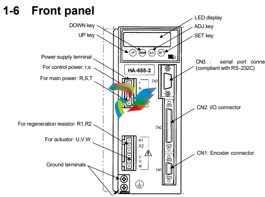
◆ LED display
Indicates operating states of the HA-655 driver, parameters, alarms, by a 6-digit 7segment-LED.
◆ Keys labeled [UP], [DOWN], [ADJ], and [SET]
Are used for changing indications, setting and tuning functional parameters, and operating an actuator
manually in a JOG mode.
◆ CN1: encoder connector
Accepts a connector of an encoder cable form an actuator.
◆ CN2: I/O connector
Accepts I/O signals to/from a host device.
◆ CN3: Serial port connector (compliant with RS-232C)
Is connected to a PC with a dedicated cable. You can monitor, set, and tune parameters on the PC’s
display. (Notice: Optional software is available.)
◆ Power supply terminals: r, s, R, S, T
Are provided for connecting the power supply. Control power is supplied to the [r, s] terminals, and main
power is supplied to the [R,S,T] terminals. (single Phase: R,S; or three phase: R,S,T).
◆ External regeneration resistor terminals: R1, R2
If the built-in regeneration resistor is insufficient in its capacity to handle frequent start/stop operations of
an actuator, an external resistor can be connected to these terminals.
◆ Actuator terminals: U, V, W
Accept an actuator cable. Connect each motor wire to the driver’s terminal marked with a same symbol.
If you confuse the symbols, the driver and the actuator may be in failure.
◆ Ground terminals (Protective earth)
Connect grounds here to prevent electrical shock.
1-7 Outlines of I/O ports
The CN2 connector provides input and output signals to and from a host device. The 50 pins of the
connector are assigned to the following signals in each of the [position mode] and the [speed mode].
(Notice: Do not connect signals to pins marked “-“.)
1-8 Operating display panel
The HA-655 driver provides a 6-digit LED display and four operation keys on the front panel. The panel
executes monitoring, tuning, setting, and JOG operation.
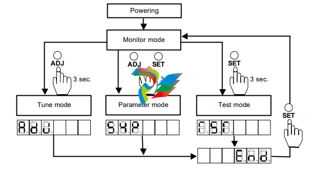
1-8-1 Outlines of operation modes
The HA-655 driver provides the following four modes: monitoring, tuning, setting, and operations.
◆ Monitor mode
The HA-655 driver displays position and speed commands, a current position from a motor-encoder, a
pulse count in an error counter, states of input and output signals, load conditions, alarm histories, and a
code number for the actuator for which the driver is set. The mode can be used for diagnosing an
abnormal driver.
After power supply, the monitor mode starts up and works as the hub of other three modes for operation.
◆ Tune mode
The tuning mode includes various parameters to control the actuator motion. Setting the most suitable
value for each parameter obtains the optimum performance of the actuator.
◆ Parameter mode
The parameter mode sets various parameter values relating to the fundamental operational functions
such as: specifications of the position mode or the speed mode, configurations of input signals, an
electronic gear function, limiting values of speed and torque, and parameters to communicate with a
host.
◆ Test mode
The test mode includes required functions for system tests; such as JOG operation functions, operations
of pseudo output signals, I/O signal monitors, and so on.
1-8-2 Selecting a mode
After powering the driver, the monitor mode starts up automatically. The [ADJ] and [SET] keys select a
mode.
1-9-2 Protective functions
The HA-655 driver provides the following alarms to protect the servo system, and presents an alarm
code on the preceding paragraph.
◆ Over speed (10)
If a motor exceeds its maximum speed or if motor rotates abnormally, the alarm occurs. To clear the
alarm, shut off the control power once and turn it on again.
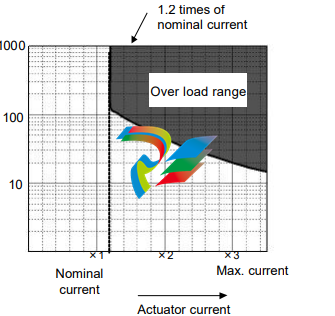
◆ Over load (20)
The driver always monitors the motor current, and if the current exceeds the curve in the figure below,
the overload alarm occurs.
For example:
(1) The alarm occurs if the current
slightly exceeds 1.2 times of
nominal current for a long
duration.
(2) The alarm occurs if the current of
three times of the nominal current
flows for 20 seconds.
It is possible to clear the alarm by
inputting signal to [CN2-2 clear:
CLEAR].
◆ Overheat (21)
The alarm occurs by activating the thermal switch of an IPM element in the HA-655 driver. To clear the
alarm after troubleshooting, shut off the control power once and turn it on again.
◆ Over current (30)
The alarm occurs when the servo control element of the driver detects excessive current. To clear the
alarm after troubleshooting, shut off the control power once and turn it on again.
◆ Abnormal regeneration (41)
The alarm occurs by activating the thermal switch of the regeneration resistor in the HA-655 driver at
100℃. To clear the alarm after troubleshooting, shut off the control power once and turn it on again.
◆ Encoder failure (50)
The alarm occurs when the encoder signal ceases. To clear the alarm after troubleshooting, shut off the
control power once and turn it on again.
The alarm also occurs when a built-in battery of the HA-655 driver for the absolute encoder is taken off in
spite of normal conditions. To clear the alarm, shut off the control power once and turn it on again.
◆ Abnormal encoder signal (51)
The alarm occurs when the driver has failed to receive two sequential signals. To clear the alarm after
troubleshooting, shut off the control power once and turn it on again.
◆ UVW failure (52)
The alarm occurs when the encoder UVW signals are abnormal. To clear the alarm after troubleshooting,
shut off the control power once and turn it on again.
◆ ABS system failure (53)
For the absolute encoder, the alarm occurs when all power supplies (power supply, built-in condenser,
and battery) for the encoder are failure. For example, it occurs at the first power supply after purchasing,
and at power supply after disconnecting the cable between the driver and the encoder for a long duration.
To recover the alarm, input the multi-turn data clear signal at least 4 seconds, and shut off the control
power once and turn it on again.
◆ ABS MTD overflow (54)
For the absolute encoder, the alarm occurs when the count for multi-turn data (MTD) goes beyond the
range of +4095 to - 4096 turns (motor axis). To recover the alarm, input the multi-turn data clear signal at
least 4 seconds, and shut off the control power once and turn it on again.
◆ ABS multi-turn data error (55)
For the absolute encoder, during an energy-saving mode, where no power by power supply but the
encoder circuit is active only by the power of a built-in condenser and a built-in battery, the alarm occurs
when the encoder rotates too fast at the acceleration rate and speed exceeding the recording ability of
the multi-turn counter on the mode. To recover the alarm, input the multi-turn data clear signal at least 4
seconds, and shut off the control power once and turn it on again.
◆ ABS low battery voltage (56)
For the absolute encoder, when voltage of the built-in battery is low. To recover the alarm, change the
battery for a new one, and shut off the control power once and turn it on again.
◆ ABS send data rule error (57)
The absolute encoder rotates more than 127 resolvable pulses by external torque during transmitting
absolute data. To recover the alarm, shut off the control power once and turn it on again.
◆ Error counter overflow (60)
The alarm occurs when an error count exceeds the set value in [parameter mode]→[6: position error
allowance]. It is possible to clear the alarm by inputting a signal to [CN2-2 clear: CLEAR]. The error
count is cleared at the same time.
◆ Memory failure (RAM) (70)
The alarm occurs when the driver’s RAM memory fails. It is impossible to clear the alarm.
◆ Memory failure (EEPROM) (71)
The alarm occurs when the driver’s EEROM memory fails. It is impossible to clear the alarm.
◆ CPU failure (76)
The alarm occurs when the driver’s CPU fails. It is impossible to clear the alarm.
Chapter 2 Functions
2-1 Control system of the HA-655 driver
It is said that [plan, do, see] is essential to perform perfect
jobs. In other words, the [plan, do, see] is the repeating
cycle of command→action→result→feedback→modified
command → action → feedback →・・・・ .
Driving machines precisely requires the same control as
the above job cycle, that is [Motion command→run→
feedback→modified command→・・・・].
For example, assume the required motion is rotation to a
target angle and stopping there. To perform the motion,
the motor must be equipped with an angular sensor to
detect a current position, and the position data must be
compared with the command. If the position data is
different than the command, the motor rotates until the
position data becomes equal to the command. This is an
example of a position servo system.
The speed control system is the same. The motor is
equipped with a speed sensor and the speed is compared
with the speed command. If the speed is different from the
command, the motor accelerates or decelerates until the
motor speed becomes equal to the command. This is an
example of the speed servo system.
The HA-655 driver realizes above both controls of position and speed with the same unit.
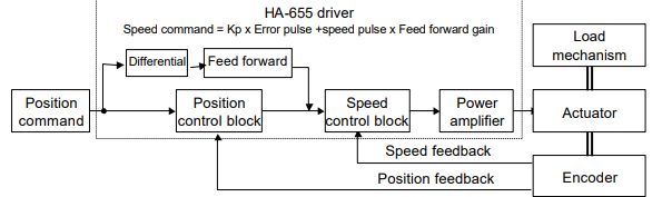
The fundamental configuration of servo system of the HA-655 driver is as follows:
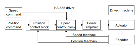
The HA-655 driver function is consists of three parts: the position control block, the speed control block,
and the power amplifier.
In the position mode, a command position from a host is compared to a feedback position. If there is a
difference between them, the position control block commands the power amplifier through the speed
control block to flow current to the actuator until there is no difference.
In the speed mode, a speed command is directly inputted to the speed control block. The speed block
compares the command and current feedback speed. If there is a difference between them, the speed
control block commands to the power amplifier flow the current to the actuator until there is no
difference.
The HA-655 driver allows two types of encoder as a functional member of the feedback system,
optionally: an incremental encoder or an absolute encoder.
2-2 Position mode
The HA-655 driver makes use of either the position control or the speed control. This section describes
the position mode. (※ The default setting is the [position mode].)
Before driving, set the control mode by [parameter mode] → [0: control mode].
2-2-1 Command configuration in position mode
In the position mode, the command is transmitted from a host in the form of a digital pulse signal train.
The HA-655 driver provides two pair of two ports (CN2-27&28, CN2-29&30) for the command pulses.
Signals of three type of configurations are available for the ports.
● Setting a command configuration
[Parameter mode]→[1: command configuration]
● Relating I/O pins
Input pins: CN2-26 to 30
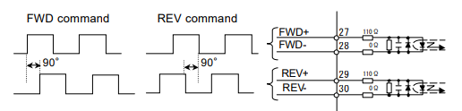
(1) 2-pulse train (FWD and REV pulse train)
Two pairs of two terminals are provided, and each of FWD and REV pulse trains is assigned a pair
independently. FWD commands and REV commands are inputted in the pair of FWD ports and REV
ports respectively, as shown in the figure below. When signals are inputted to a pair of terminals, the
signal to the other should keep [OFF] state.
(2) 1-pulse train (polarity + pulse train)
One pair of terminals is assigned dedicatedly for command pulse train, and the other is assigned to a
sign for rotary direction. Position commands are inputted in the FWD port pair only and the REV port pair
accepts the sign of rotary direction, as shown in the figure below. [OFF] or [Low level] state is for the
FWD command and [ON] or [High] level is for the REV command.
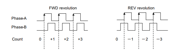
2-phase pulse train (A-B phase pulses with 90 degree difference)
Both port pairs receive the command pulse trains that have a 90 electric degree difference relative to
each other as shown in the figure below. For the FWD command, the pulse train to the FWD ports
advances 90 degrees from the REV port train. For the REV command, the REV port train advances from
the FWD port train.
The encoder pulse trains to the driver have this 2-phase pulse configuration
◆ Multiplication of command
When the command configuration is a
[2-phase pulse] type, it is possible to multiply
the command pulse train by 2 or 4 for the
command pulse train to an actuator.
The encoder feedback pulse train is
quadrupled.
● Setting
[Parameter mode] → [2: multiplication of
2-phase pulse]
◆ Electronic gear
The electronic gear function can be set make a given
displacement of the driven mechanism for one
command pulse, an integer, or a convenient number.
For example, it is convenient to set the displacement of
0.1 micrometer for one pulse as shown in figure to the
right.
The function multiples the command pulse count by the
coefficient (fraction).
The relation of [denominator / numerator] of the coefficient
is obtained as follows:
2-2-2 Command transmitting system
Two systems are provided for transmitting command pulses: [open collector] and [line driver].
◆ Open collector system
This system employs a transistor whose emitter is
common and whose collector is open. Since the
output signal is voltage type, this system is
unsuitable for long distance transmission due to line
voltage drop.
◆ Line driver system
The line driver system conforms to (EIA) RS-422
standard providing line drivers for transmitting
signal pulses. Since the output signal is current type,
this system is suitable for long distance
transmissions without attenuation of signals.
Furthermore, the line driver system transmits data
faster than the open collector system.
2-2-3 Outputting encoder signals
Two kinds of encoder are selectable for the FHA-C
series actuator: incremental or absolute. The
incremental encoder feeds back two pulse-trains
into the HA-655 driver as shown in the figure to the
right. The pulse trains are called [phase-A] and
[phase-B]. For the encoder resolution, refer to
actuator’s technical manual.
On the other hand, the absolute encoder feeds back
a combination of absolute signals and two
pulse-train signals.
In addition to the 2-phase pulse trains, both
encoders output a [phase-Z] pulse signal once per
motor rotation for use as an origin. The pulse signal
is sometimes called [phase-C] or [index].
The HA-655 driver outputs encoder signals using a
line driver system. The signals can be received by a
line receiver: AM26LS32 (EIA-422A) or equivalent.
Phase-Z signal is also available (open collector
output {CN-42 pin}).
The phase-Z signal is asynchronous.
Three encoder signals mentioned above are
available for a host.
● Relating I/O pins
Output pins: CN2-42 to 49
2-2-4 Absolute encoder signals
u General descriptions and functions of absolute encoders
The absolute encoder housed in a FHA-C series actuator provides an absolute sensor to generate an
absolute pulse train for a resolvable position (the sensor is herein after referred to as “single-turn
encoder”.), and an electronic counter to generate an absolute pulse train for a revolution of the motor
(the counter is hereinafter referred to as “multi-turn counter”.).
An absolute position of the encoder is kept in the memory, which is always energized by a combination
of the built-in condenser in the actuator and the backup battery housed in the HA-655 driver.
Please interpret that “single-turn” and “multi-turn” in the manual mean one and plural revolutions of the
encoder (the motor) in an actuator, respectively. Therefore, the actual actuator resolvable position of
either “single-turn” or “multi-turn” can be obtained by multiplying an absolute pulse train of the single-turn
encoder and the multi-turn counter by a reduction ratio of the actuator.
u Single-turn absolute encoder
The single-turn encoder is composed of an encoder disk, an LED light source, and a photo-detector. The
single-turn absolute encoder system outputs a current absolute pulse train combined with an absolute
pulse train of the multi-turn counter in response to the [ABS data request] signal. The resolution of the
encoder is 8192 positions per turn (13 bits). To obtain actual resolvable position of the actuator, the
absolute pulse train should be multiplied by the reduction ratio of the actuator.
u Multi-turn counter
The multi-turn counter outputs a current absolute pulse train combined with an absolute pulse train of
the single-turn absolute encoder system in response to the [ABS data request] signal. The allowed
range of the counter is from +4095 to –4096. To obtain an actual resolvable position of the actuator, the
absolute pulse train should be multiplied by the reduction ratio of the actuator.
u Energy-saving mode
In the energy-saving mode, even during no power supply for the HA-655 driver, the multi-turn counter
keeps a count in its memory only by the power of a built-in condenser and a built-in battery.
u Allowable encoder (motor) speed in energy-saving mode
The limit of an encoder (a motor) speed is 5,000r/min. The [alarm 55: ABS multi-turn data error] occurs if
the encoder rotates at more than the limited speed, and a correct absolute pulse train of the multi-turn
counter may not obtained. Moreover, there are additional limits during motor acceleration duration as
shown the figure below
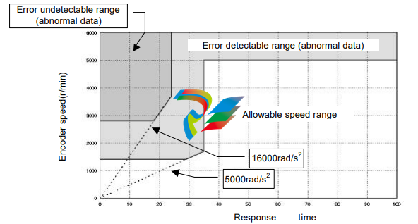
u Notice at power on If power is turned on while the motor rotates at 2800r/min or more, the [Alarm 55] may occur. In spite of the alarm, the multi-turn counter works normal. u ABS (multi-turn) data clear signal (CN2-11: ABS-CLEAR) The ABS (multi-turn) data clear signal should be inputted at: (a) the initial power supply, and; (b) wasting about 30 minutes or more for exchanging the built-in battery. At either case, the multi-turn counter does not keep any data. To recover from the problem, move the actuator to a proper origin and input the [ABS (multi-turn) data clear signal] at least four seconds to clear the multi-turn counter to zero. However, the single-turn encoder keeps its resolvable position during above-mentioned operation firmly. During exchanging the battery, the built-in condenser helps the multi-turn counter to keep its count at least about 30 minutes with charged energy in the condenser. Therefore, the operation of inputting [ABS (multi-turn) data clear signal] is not required before discharging the energy. Though the [alarm 50: encoder failure] may occur at power ON operation after exchanging the battery, the encoder system is normal. To recover the problem, shut off the power once and turn it on again. u Acquisition of absolute pulse trains generated by absolute encoder system The HA-655 driver provides two selectable acquisition methods of absolute pulse trains generated by the absolute encoder system; from I/O ports and from CN3 port (RS-232C). (a) Acquisition from I/O ports (CN2-44, -45 and CN2-46, -47) Acquiring an absolute pulse train An absolute pulse train of an absolute encoder system is a combination of an absolute code (13 bits) of the multi-turn counter expressing an encoder’s revolution number from its origin, and an absolute code (13 bits) of the single-turn encoder expressing a resolvable position of the encoder (the motor). Incremental signal trains following to the absolute pulse train of an absolute encoder system may be used for monitoring signals of operating condition of the motor. As a rule, acquiring an absolute pulse train is possible only one time during power ON procedure illustrated below. If acquiring an absolute pulse train is required at another timing, use the CN3 port for acquiring while the motor is stopping.
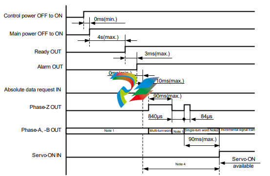
Note 1: Both output signals of phase-A and phase-B are settled at LOW-level. To settle at LOW-level, at
least three pulses are outputted. Make a sequence for the host device ignoring outputted pulses while the
phase-Z is LOW-level before generating an absolute pulse train, and during other LOW-level duration of
the phase-Z signal.
Note 2: An absolute pulse train for single-turn encoder is outputted after around 1 ms of outputting
phase-Z signal.
Note 3: The servo-ON signal is unaccepted until completing the transmission of a set of absolute pulse
trains by the [absolute data request] signal.
Note 4: The [alarm 57] occurs if the single-turn encoder rotates more than 127 resolvable position while
the multi-turn counter is transmitting an absolute pulse train.
Acquiring multi-turn count
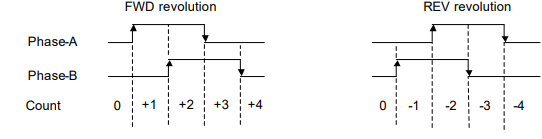
For FWD revolution of the encoder (motor), the phase-A signal has 90 degree phase shift against
phase-B signal, and for REV revolution the phase-A signal has 90 degree phase delay against phase-B
signal as shown below.
Increasing or decreasing the multi-turn counter of the host device should be discriminated by the phase
shift or delay of phase-A against phase-B. Acquire the signal at rising edge of the signal
For FWD revolution of the encoder (motor), the phase-A signal has 90 degree phase shift against
phase-B signal, and for REV revolution the phase-A signal has 90 degree phase delay against phase-B
signal as shown below.
Increasing or decreasing the single-turn encoder counter of the host device should be discriminated by
the phase shift or delay of phase-A against phase-B. Acquire the signal at rising and falling edge of the
signal.
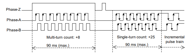
An example of signal transmission
The following is an example of the multi-turn count: 8, single-turn encoder count: 25 and an incremental
pulse train at a usual operation.
The actual resolvable position of the encoder (motor) can obtained by the calculation of:
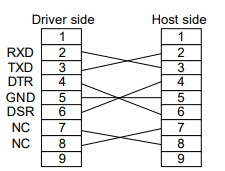
(b) Acquiring from CN3 port (RS-232C)
Connecter specifications
Connect an RS-232C cable having following specifications between the CN3 port of the HA-655 driver
and a RS-232C port of a host device.
Connecters: D-sub connecter having 9 female pins
Pin assignments:
Sending a command to HA-655 driver (host →HA-655)
The command should be 10 characters in length including a delimiter as illustrated below. The
HA-655 driver waits until receiving 10 characters without any processing. Make sure that the
message has 10 characters including a delimiter.
(1) The first function of the [position control block] is the [error count] calculation by the [error counter]
in the block subtracting a feedback count from a command count.
(2) The second function is the block that converts the [error count] to a [speed command] multiplying a
factor, and then transmits the [speed command] to the [speed control block]. The factor (Kp) is
called [position loop gain].
It is clear in the formula that a large [error pulse] is converted into a high [speed command] and a
zero pulse into a zero speed command, in other words, a stop command.
(3) If the [position loop gain (Kp)] is high, a small [error count] is converted into a higher [speed
command]. That is to say, higher gain provides the servo system with better response.
However, very high gain commands result in high [speed commands] from very minimal [error
count] which will result in overshooting. To compensate for the overshoot the [position control block]
generates a high speed reverse command, then overshoots in the opposite direction * * * finally
hunting motion may take place.
Conversely, if the [position loop gain (Kp)] is very low, you will get very slow positioning motion
(undershoot), and a poor servo response.
(4) In conclusion, it is important to set the optimum value to the [position loop gain (Kp)]. The HA-655
driver has been set with the most suitable value for general applications as a factory default. If the
load inertia is very heavy and the default is not suitable, tune it carefully.
◆ [Speed control block], [speed loop gain], and [speed loop integral compensation]
(1) The first function of the [speed control block] is to subtract a feedback signal from a command
signal.
(2) The second function is the block converts the difference to a [current command] multiplies it by a
factor, and then transmits the [current command (I)] to the [power amplifier]. The factor (Kv) is
called [speed loop gain].
It is clear in the formula that a significant [speed difference] is converted into a high [current
command] and zero difference into zero current command, in other words, a stop command.
(3) Just as with the [position loop gain], higher gain provides better response and excessive gain
results in hunting. Low gain requires no hunting but raises the occurrence of undershoots.
(4) The [speed loop integral compensation (Tv)] of The HA-655 driver makes less influence on load
fluctuation.
If the [speed loop integral compensation (Tv)] is smaller, the speed response to the load fluctuation
becomes better, but too small a value results in hunting. Excessive compensation requires no
hunting, but will result in a poor response for load fluctuation.
● Tuning method
[Tune mode]→[0.speed loop gain], and [1: speed loop integral compensation]
◆ Feed forward gain
(1) In the position mode The HA-655 driver controls the error count, (the difference between
[command pulse] and [feedback pulse]), to be [0]. At the beginning of inputting a command pulse
train, the actuator starts slowly because of small error count.
(2) The [feed forward] function may accelerate the actuator as much as possible, adding speed pulses
converted from the command pulse frequency directly to the driver’s speed control loop
) The relation between the feed forward and actuator motion is as follows:
Higher feeding allows for better following to command, but excessive feeding results in hunting and
erratic motion.
Low feeding requires no hunting but a poor following of the command.
● Tuning method
[Tune mode]→[3:Feed forward]
2-2-5 FWD inhibit and REV inhibit
The HA-655 driver provides [FWD inhibit] and [REV inhibit] input signal ports.
[FWD inhibit]: opening (OFF) the input inhibits forward rotation.
[REV inhibit]: opening (OFF) the input inhibits reverse rotation.
Opening (OFF) both inputs inhibits all rotation.
The inputs may be used to limit the motion range between limit sensors.
2-2-6 In-position
In the position mode, even though the driver controls the actuator to make the [error count 0], it is not
always possible due to the influence of external forces, acceleration, and deceleration. Establishing a
positioning allowance is a good solution to the problem; that is [in-position range].
[Tune mode]→[4: in-position range] sets the allowance. The actuator position comes within the range
calculated with the formula below, the [CN2-33: in-position] signal outputted.
2-3 Speed mode
The HA-655 driver makes use of either the position control or the speed control. This section describes
the speed mode. (※ The default setting is the [position mode].
Before running, set the control mode by [parameter mode] → [0: control mode].
2-3-1 Speed conversion factor
In the speed mode, the command is sent from a host with an analog voltage signal. The [speed
conversion factor] converts the [speed command] voltage to motor speed.
The [speed conversion factor] is the motor speed when the [speed command voltage] is [10V]. The
actual motor speed is obtained by the following formula:
The [speed monitor] (SPD-MON: CN2-23pin) output voltage as follows:
● Setting
[Parameter mode]→[9: speed conversion factor]
2-3-2 Voltage of speed command
Input the voltage converted by the [speed conversion factor] into [CN2-31: speed command] and
[CN2-32: speed command common] pins. The [speed command voltage] is obtained by [parameter
mode]→[9: speed conversion factor].
◆ FWD enable and REV enable
The HA-655 driver provides [FWD enable] and [REV enable] input ports. The rotary direction of the
actuator is decided by the polarity of [CN2-31: speed command SPD-CMD] and ON/OFF states of [FWD
enable] and [REV enable] as shown in the table below:
CN2-31 Speed cmd.: SPD-CMD +Command -Command
CN2-4 FWD enable: FWD-EN ON OFF ON OFF
CN2-5 REV enable: ON Zero clamp, zero speed REV rotation Zero clamp, zero speed FWD rotation
REV-EN OFF FWD rotation Zero clamp, zero speed REV rotation Zero clamp, zero speed
● Relating input pins
CN2-31: speed command, CN2-32: speed command common, CN2-4: FWD enable,CN2-5:REV enable
◆ Speed command offset
In the speed mode, the motor may rotate slightly in spite of a [0V] speed command voltage. This problem
may occur when the speed command voltage has an offset of a few milli-volts. This function removes the
slight rotation compensating the command voltage offset.
While inputting a [OV] command voltage adjust the speed command offset until the actuator stops
rotating.
[Speed command automatic offset] function is also provided.
● Setting
[Tune mode]→[9: speed command offset], [test mode]→[So: Speed command automatic offset]
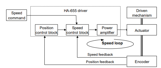
In the figure, the closed loop of [speed control block]→[power amplifier]→[actuator]→[encoder]→[speed
control block] is called [speed loop].
The details of the loop are described as follows:
◆ [Speed control block], [speed loop gain], and [speed loop integral compensation]
(1) The first function of the [speed control block] is to subtract a feedback signal from a command
signal.
(2) The second function is when the block converts the difference to a [current command] multiplies it
by a factor, and then transmits the [current command] to the [power amplifier]. The factor (Kv) is
called [speed loop gain].
It is clear in the formula that a [speed difference] is converted into a high [current command], and a
zero difference into a zero current command, in other words, a stop command.
(3) If the [speed loop gain (Kv)] is high, a small [speed command] is converted into a higher [current
command]. That is to say, higher gain provides the servo system with a better response.
However, very high gain settings can cause a very high [current command] in response to a small
[speed command] which will result in overshooting. To compensate overshooting, the [speed
control block] generates a high speed reverse command, then ・・・・・・・・・finally hunting motion
may take place.
(4) Conversely, if the [speed loop gain (Kv)] is very low, you will get very slow positioning motion
(undershoot) and poor servo response.
(5) The [speed loop integral compensation (Tv)] of the HA-655 driver minimizes the influence of load
fluctuation.
If the [speed loop integral compensation (Tv)] is low, the speed response to the load fluctuation
becomes better, but very small value can result in hunting. Excessive compensation requires no
hunting but a poor response for load fluctuation.
● Setting
[Tune mode]→[0: speed loop gain], [1: speed loop integral compensation]
2-3-4 Command change
The function can operate the actuator without command at the speed specified by [tune mode]→[6:
internal speed command]. This is convenient for diagnosis and for test operation without hosts.
The actuator will rotate at the speed set by the [internal speed command] when a signal is input to
CMD-CHG (CN2-6) and stops when the signal is removed.
● Relating I/O pin
Input pin: CN2-6
2-3-5 Acceleration / deceleration time constants
[Acceleration time constant] is the time it takes to accelerate the motor from [0 r/min] to the speed of [A:
speed limit] of [parameter mode].
[Deceleration time constant] is the time it takes to decelerate the motor from the speed of [A: speed limit]
of [parameter mode] to [0 r/min].
The deceleration time to speed command voltage is as follows:
2-3-6 Zero clamp
In the speed mode when [speed command] is [0], the actuator may rotate slightly by force from the
driven mechanism. The [Zero clamp] function forcefully stops the actuator when the speed command is
[0].
● Setting
[Parameter mode]→[7: zero clamp]
Take cares that the servo-lock function does not work and the
actuator is free to rotate when:
- main and/or control power are not supplied;.
- servo-ON signal is not inputted;
- an alarm occurs
2-4 Other functions
2-4-1 Indicating of pulse counts
As shown in the figure to the right, the motion
command pulses are transmitted to the HA-655
driver from a host. The driver drives the actuator
corresponding to the motion command. When the
actuator starts, the position pulses are sensed by
the encoder and are fed back to the driver. The
HA-655 driver continues to drive the actuator until
the error count (difference between command count
and feedback count) comes to zero.
In the monitor mode, [command pulse], [feedback pulse], and [error pulse] can be monitored. This
function may be effective for diagnosis.
● Indications
[Tune mode]→[3,4: error counter status], [7,8: feedback pulse], [9,A: command pulse]
2-4-2 Manual JOG operation
It is possible to operate the actuator manually for test, for tuning, and for diagnosis without commands
from a host. Pressing the [UP] and [DOWN] keys on the front panel rotates the actuator at pre-set speed
and at pre-set acceleration.
● Operation and setting
[Test mode]→[Jo: JOG operation], [SP: JOG speed], [Ac: JOG acceleration]
2-4-3 Monitoring inputs and operating outputs
It is possible to monitor input ports of [clear], [servo -ON], [FWD inhibit] and [REV inhibit] for test, for
tuning, and for diagnosis.
It is also possible to manually output signals of [in-position], [attained speed], [alarm] and so on without
relations to the actuator state by pressing the [UP] and [DOWN] keys on the front panel outputs signals.
● Operation and setting
[Test mode]→[b:I/O monitor], [InP:Output port operation]
Chapter 3 I/O ports
Through the CN2 connector (50 pins; half pitch) the HA-655 driver communicates with a host. Details of
the I/O ports are described in this chapter.
As the functions of the pins of the connector differ in each control mode, the functions are described
separately by modes.
3-1 Position mode
3-1-1 I/O port layout
3-1-3 I/O port connections in the position mode
This section describes the connection between the I/O ports and a host in the position mode
Inputs:
The HA-655 driver provides six ports
for inputs as shown in the figure to the
right.
◆ Specifications
Voltage: DC24V±10%
Current: 20mA or less
(for each port)
An input port circuit is shown in the
figure to the right. The ports marked
with (*) are available for absolute
encoder system only.
● Connection
The HA-655 driver does not provide
the power supply for input signals.
Connect a [+24V] power supply for the
signals to [CN2-1: input signal
common].
Outputs:
The HA-655 driver provides eight ports
for outputs as shown in the figure to
the right.
◆ Specifications
Port: Open collector
Voltage: DC24V or less
Current: 40mA or less
(for each port)
All ports are insulated by opto-isolators.
An output port circuit is shown in the
figure to the right.
3-1-4 I/O port functions in the position mode
This section describes I/O port functions in the position mode.
CN2-1 Input signal common: IN-COM (input)
● Function
This is the common port for inputs: [CN2-2, -3, -4, -5, -10, -11]. Supply external power for inputs to this
the port.
● Connection
Connect [+24V] external power supply for inputs here.
CN2-2 Clear: CLEAR (input)
● Function
(1) If alarm exists:
This clears the alarm state, returns to operable state, and clears the error count to [0]. For alarms
that cannot be cleared, shut off the control power once, and turn it on again.
(2) If no alarm exists:
This clears the error count to [0]. At the same time, this clears the command count and the feedback
count.
● Connection
Connect [NO-contact signal (a-contact)]. Refer to [CN2-1: input signal common].
CN2-3 Servo-ON: S-ON (input)
● Function
This turns the servo power for the HA-655 driver ON and OFF.
When the input is ON, the servo power of the HA-655 driver is ON and the actuator can be driven. When
OFF, the servo power turns OFF and the motor is free to rotate.
● Connection
Connect [NO-contact signal (a-contact)]. Refer to [CN2-1: input signal common].
CN2-4 FWD inhibit: FWD-IH (input)
CN2-5 REV inhibit: REV-IH (input)
● Function
[FWD inhibit]: open state (OFF) of the input inhibits forward rotation.
[REV inhibit]: open state (OFF) of the input inhibits reverse rotation.
Open states (OFF) of both inputs inhibit rotation.
The inputs may be used to limit the motion range between limit sensors.
-
 Beckhoff PLC module CX1020-0000 Basic CPU module (service phase)
 -
 Beckhoff CP7812-1056-0010 15" Multitouch Display Control Panel
 -
 Beckhoff CX5120-0115 /2GB Controller Module
 -
 Beckhoff CP7201-1000-0000 Industrial Panel PC
 -
 Beckhoff Servo Motor AM8061-0JH1-0000
 -
 BECKHOFF CP6503-0001-0050 Built-in Panel PC
 -
 Beckhoff CP3919-0010 Display G190ETN01.2 19" PCT V04. Multi-touch Control Panel
 -
 Beckhoff CX5110-0112-9020/000368201 Embedded PC Intel Atom Processor
 -
 Beckhoff AX8206-0000 Dual-Axis Module
 -
Beckhoff Nail Operating Terminal CP7032-1031-0010
-
Beckhoff AM8042-0EH1-0000 Servomotor 4.10 Nm (M0), F4 (87 mm)
-
 Beckhoff EK9300 Beckhoff CPU Module
 -
Beckhoff CP3224-0020 Multitouch-Panel-PC
-
 Beckhoff CP2712-0000 12.1" 24VDC Touch Screen WMD0
 -
 BECKHOFF CX5240-0195 / 0000289234 Embedded PC 40 GB CFast Card
 -
 Beckhoff CP6932-1000-0000 Control Panel
 -
 BECKHOFF CX5120-0121 PLC Module
 -
 Beckhoff EL3218 | EtherCAT Terminal, 8-channel analog input
 -
 Beckhoff C6640-0050 | Control cabinet Industrial PC
 -
 Beckhoff Cx5130-0120/4GB Embedded-PC
 -
 BECKHOFF CX2030-0122 PLC PROCESSOR
 -
 BECKHOFF CX5020-0122 Controller Module
 -
 Beckhoff CP3915-0000 Multitouch Panel
 -
 BECKHOFF EL3014 | EtherCAT Terminal
 -
 BECKHOFF Industrial Computer c6920-1057-0030
 -
 Beckhoff CX5130-0141/4GB CX5130-0141 Embedded PC
 -
 Beckhoff C6240-1052-0040 4-086-06-3073 Industrial Computer
 -
 Beckhoff CX5140-0135 /4GB High-Performance Embedded Industrial PC
 -
 Beckhoff C6515-1001-0000 Industrial PC
 -
 Beckhoff AX5103-0000-0200 - Digital Compact Servo Drives
 -
 Beckhoff CX2030-0130-1003/4GB Basic CPU module
 -
 Beckhoff AX8620-0000 Power Supply Module
 -
 Beckhoff CX9020-0111 module with
 -
 Beckhoff EL7332 PLC Module
 -
 BECKHOFF CP7709-0001-0020 HMI
 -
 Beckhoff CX5120-0155/2GB Embedded PC
 -
 BECKHOFF CP7037-1037-0010 OPERATOR INTERFACE TOUCHSCREEN
 -
 Beckhoff EK9000 | ModbusTCP/UDP Bus Coupler
 -
 Beckhoff Touch Panel Screen CP6020 -0000-0000
 -
 Beckhoff CX2020-0121 Module FAST Shipping
 -
 Beckhoff CX2030-0125 Basic CPU Module
 -
 Beckhoff CP3918-0000 Multi-Touch 18.5" Control Panel
 -
 Automotion LC4A00010 DC BL Motor Control, ATS, Sub Assy, SCP, 115VAC,
 -
 500T-115VAC - VAS ENGINEERING - DORIC 500 SERIES DIGITAL TEMP INDICATOR
 -
 Honeywell X-DCS2000/EN Digital Integrated System Manager 50/60Hz 100-240V #4
 -
 Kollmorgen S60600 Servostar600 606-Fan 4 kVA, 6 A, 3 X 230 - 480 V
 -
 ABB XZ C828 A101 Didt Dioder Snubber 3BHE039453R0101
 -
 ABB 3BHB027232R0001 1-Phase Charging Transformer
 -
 ABB 3BHE006412R0101 Circuit Board UFC762AE101
 -
 ABB XVC770BE101 3BHE021083R0101 Circuit Board
 -
 ABB 3BHE021887R0101 (Model: UBCC717BE101 / UBC717BE101) is an advanced
 -
 ABB 3BHE032593R0001 Isolated Power Supply
 -
 ABB 3BSC610023R0001 POWER SUPPLY SD812
 -
 Beckhoff C6650-0060 | Control cabinet Industrial PC
 -
 Beckhoff CP2916-0000 Industrial HMI Display Panel
 -
 Beckhoff AM8053-0L2B-0000 Servomotor 15.4 Nm (M0), F5 (104 mm)
 -
 Beckhoff CP6202-0001-0020 Industrial Panel PC
 -
Beckhoff CX2020-0120 Plc Module
-
 Beckhoff CX1010-0111 BASIC CPU MODULE
 -
 Beckhoff C6017-0010 | Ultra-compact Industrial PC
 -
 BECKHOFF CX2040-0155 Plc Module
 -
 Beckhoff CX5120-0125 Embedded PC
 -
 BECKHOFF C6930-0040 INDUSTRIAL CONTROL COMPUTER
 -
 Beckhoff CP6907-0001-0000 Economy Built-in Control Panel
 -
 Beckhoff CP2912-0000 Multi-Touch Built-In Control Panel
 -
 Beckhoff C6015-0010 Ultra-Compact Industrial PC
 -
 Beckhoff CX5130 | Embedded PC with Intel Atom® E3827
 -
 Beckhoff C6030-0060 Ultra-Compact Industrial PC
 -
 OMRON 3G3XV-A2007 3G3XV-A2007-NEV2
 -
 Omron NJ1019000 NJ1 programable logic controller
 -
 OMRON C120-LK202-EV1/C120LK202EV1
 -
 OMRON C200H-AD003 PLC
 -
 OMRON C200H-CPU23-E COIL 24VDC PLC
 -
 Omron C200HG - C200H-ID212- C200H-OC226 C200HW-BC101 PLC Base Unit
 -
 OMRON C200H-OC222(Output Unit),C200H-PS211(Power Supply Unit),SP001 Module Rack
 -
 OMRON C200H-RT201 PROGRAMMABLE CONTROLLER
 -
 OMRON C200HS-CPU01-E SYSMAC PROGRAMMABLE CONTROLLER
 -
 OMRON C200H-SNT31 C200H Programmable Controllers
 -
 OMRON C200HW-MC402-E Motion control unit
 -
 OMRON C200PC-ISA02-DRM-E PLC ISA bus compatible board card
 -
 OMRON C500-CT012 PLC
 -
 OMRON C500-NC103-E PLC
 -
 OMRON C500-NC222-E PLC
 -
 OMRON C500-PRW05-V1 PLC
 -
 OMRON C500-PRW06 PROGRAMMABLE CONTROLLER
 -
 OMRON C500-PS223-E 3G2A5-PS223-E PLC SYSMAC PROGRAMMABLE CONTROLLER
 -
 OMRON C500-TU001 3G2A5-TU001 PLC PLC
 -
 OMRON C60H-C1DR-DE-V1 Programmable Controllers
 -
 OMRON C60H-C5DR-DE-V1 Programmable Controllers
 -
 OMRON C60H-C6DR-DE-V1 Programmable Controllers
 -
 OMRON CJ1G-CPU44H CPU module
 -
 OMRON CJ1G-CPU45H PLC
 -
 OMRON CJ1M-CPU13-ETN V4.0 PLC PLC
 -
 OMRON CJ1W-AD041-V1 Analog input uni
 -
 OMRON CJ1W-CORT21 PLC module
 -
 OMRON CJ1W-IDP01 Input unit
 -
 OMRON CJ1W-MCH71 - MECHATROLINK-II
 -
 OMRON CJ1W-MD261 Digital I/O
 -
 OMRON CJ1W-NC413 Position control unit
 -
 OMRON CJ1W-NCF71 Position Control Units
 -
 OMRON CJ1W-PTS51 Process Simulation I/O Module
 -
 OMRON CJ1W-PTS52 Process Simulation I/O Module
 -
 OMRON CJ1W-SCU21-V1 PLC
 -
 Omron CJ1W-SCU22 Serial Communication Unit
 -
 OMRON CJ1W-TC001 CJ Series Temperature Control Unit
 -
 Omron CK3W-AX1515N Motion Controller
 -
 Omron CP1E-N60DR-D Compact PLC CPU
 -
 OMRON CP1E-NA20DT1-D PLC PLC
 -
 OMRON CP1H-X40DT-D plc PLC
 -
 OMRON CPM2C-S110C-DRT Interface module
 -
 OMRON CQM1-AD041 PLC
 -
 SAACKE F‑GDSA‑1 / F‑GDSA‑2 Feuerungsautomaten
 -
 SAACKE F-GDSA 143303 Controller SHIPS UPS
 -
 ICS Triplex T8270 Trusted 24 Vdc FanAssembly
 -
 SCHNEIDER M522220000 SA SM_DO16R 16 DIGITAL OUTPUTS MODULE
 -
 LENZ EPL10200-W EPZ-10203 CANPT010W3E
 -
 OMRON CQM1H-ADB21 PLC
 -
OMRON CQM1H-CPU61 PLC
-
 OMRON CQM1H-MAB42 PLC
 -
 OMRON CQM1-TC102 CQM1-TC101 PLC
 -
 OMRON CS1G-CPU44-EV1 PLC
 -
 OMRON CS1G-CPU44H CPU
 -
OMRON CS1H-CPU63-EV1 PLC
-
 OMRON CS1H-CPU66-V1 PLC
 -
 OMRON CS1W-CLK13 PLC communication module
 -
OMRON CS1W-EIP21 PLC
-
 OMRON CS1W-MAD44 PLC PLC
 -
 OMRON CS1W-SCU31-V1 CVM1-BC103 PLC


