
HarmonicHarmonic Drive™ servo
display. (Notice: Optional software is available.)
◆ Power supply terminals: r, s, R, S, T
Are provided for connecting the power supply. Control power is supplied to the [r, s] terminals, and main
power is supplied to the [R,S,T] terminals. (single Phase: R,S; or three phase: R,S,T).
◆ External regeneration resistor terminals: R1, R2
If the built-in regeneration resistor is insufficient in its capacity to handle frequent start/stop operations of
an actuator, an external resistor can be connected to these terminals.
◆ Actuator terminals: U, V, W
Accept an actuator cable. Connect each motor wire to the driver’s terminal marked with a same symbol.
If you confuse the symbols, the driver and the actuator may be in failure.
◆ Ground terminals (Protective earth)
Connect grounds here to prevent electrical shock.
1-7 Outlines of I/O ports
The CN2 connector provides input and output signals to and from a host device. The 50 pins of the
connector are assigned to the following signals in each of the [position mode] and the [speed mode].
(Notice: Do not connect signals to pins marked “-“.)
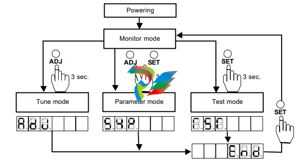
1-8 Operating display panel
The HA-655 driver provides a 6-digit LED display and four operation keys on the front panel. The panel
executes monitoring, tuning, setting, and JOG operation.
1-8-1 Outlines of operation modes
The HA-655 driver provides the following four modes: monitoring, tuning, setting, and operations.
◆ Monitor mode
The HA-655 driver displays position and speed commands, a current position from a motor-encoder, a
pulse count in an error counter, states of input and output signals, load conditions, alarm histories, and a
code number for the actuator for which the driver is set. The mode can be used for diagnosing an
abnormal driver.
After power supply, the monitor mode starts up and works as the hub of other three modes for operation.
◆ Tune mode
The tuning mode includes various parameters to control the actuator motion. Setting the most suitable
value for each parameter obtains the optimum performance of the actuator.
◆ Parameter mode
The parameter mode sets various parameter values relating to the fundamental operational functions
such as: specifications of the position mode or the speed mode, configurations of input signals, an
electronic gear function, limiting values of speed and torque, and parameters to communicate with a
host.
◆ Test mode
The test mode includes required functions for system tests; such as JOG operation functions, operations
of pseudo output signals, I/O signal monitors, and so on.
1-8-2 Selecting a mode
After powering the driver, the monitor mode starts up automatically. The [ADJ] and [SET] keys select a
mode.
1-9-2 Protective functions
The HA-655 driver provides the following alarms to protect the servo system, and presents an alarm
code on the preceding paragraph.
◆ Over speed (10)
If a motor exceeds its maximum speed or if motor rotates abnormally, the alarm occurs. To clear the
alarm, shut off the control power once and turn it on again.
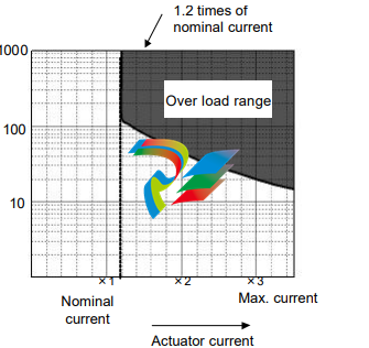
◆ Over load (20)
The driver always monitors the motor current, and if the current exceeds the curve in the figure below,
the overload alarm occurs.
For example:
(1) The alarm occurs if the current
slightly exceeds 1.2 times of
nominal current for a long
duration.
(2) The alarm occurs if the current of
three times of the nominal current
flows for 20 seconds.
It is possible to clear the alarm by
inputting signal to [CN2-2 clear:
CLEAR].
◆ Overheat (21)
The alarm occurs by activating the thermal switch of an IPM element in the HA-655 driver. To clear the
alarm after troubleshooting, shut off the control power once and turn it on again.
◆ Over current (30)
The alarm occurs when the servo control element of the driver detects excessive current. To clear the
alarm after troubleshooting, shut off the control power once and turn it on again.
◆ Abnormal regeneration (41)
The alarm occurs by activating the thermal switch of the regeneration resistor in the HA-655 driver at
100℃. To clear the alarm after troubleshooting, shut off the control power once and turn it on again.
◆ Encoder failure (50)
The alarm occurs when the encoder signal ceases. To clear the alarm after troubleshooting, shut off the
control power once and turn it on again.
The alarm also occurs when a built-in battery of the HA-655 driver for the absolute encoder is taken off in
spite of normal conditions. To clear the alarm, shut off the control power once and turn it on again.
◆ Abnormal encoder signal (51)
The alarm occurs when the driver has failed to receive two sequential signals. To clear the alarm after
troubleshooting, shut off the control power once and turn it on again.
◆ UVW failure (52)
The alarm occurs when the encoder UVW signals are abnormal. To clear the alarm after troubleshooting,
shut off the control power once and turn it on again.
◆ ABS system failure (53)
For the absolute encoder, the alarm occurs when all power supplies (power supply, built-in condenser,
and battery) for the encoder are failure. For example, it occurs at the first power supply after purchasing,
-
 Beckhoff PLC module CX1020-0000 Basic CPU module (service phase)
 -
 Beckhoff CP7812-1056-0010 15" Multitouch Display Control Panel
 -
 Beckhoff CX5120-0115 /2GB Controller Module
 -
 Beckhoff CP7201-1000-0000 Industrial Panel PC
 -
 Beckhoff Servo Motor AM8061-0JH1-0000
 -
 BECKHOFF CP6503-0001-0050 Built-in Panel PC
 -
 Beckhoff CP3919-0010 Display G190ETN01.2 19" PCT V04. Multi-touch Control Panel
 -
 Beckhoff CX5110-0112-9020/000368201 Embedded PC Intel Atom Processor
 -
 Beckhoff AX8206-0000 Dual-Axis Module
 -
Beckhoff Nail Operating Terminal CP7032-1031-0010
-
Beckhoff AM8042-0EH1-0000 Servomotor 4.10 Nm (M0), F4 (87 mm)
-
 Beckhoff EK9300 Beckhoff CPU Module
 -
Beckhoff CP3224-0020 Multitouch-Panel-PC
-
 Beckhoff CP2712-0000 12.1" 24VDC Touch Screen WMD0
 -
 BECKHOFF CX5240-0195 / 0000289234 Embedded PC 40 GB CFast Card
 -
 Beckhoff CP6932-1000-0000 Control Panel
 -
 BECKHOFF CX5120-0121 PLC Module
 -
 Beckhoff EL3218 | EtherCAT Terminal, 8-channel analog input
 -
 Beckhoff C6640-0050 | Control cabinet Industrial PC
 -
 Beckhoff Cx5130-0120/4GB Embedded-PC
 -
 BECKHOFF CX2030-0122 PLC PROCESSOR
 -
 BECKHOFF CX5020-0122 Controller Module
 -
 Beckhoff CP3915-0000 Multitouch Panel
 -
 BECKHOFF EL3014 | EtherCAT Terminal
 -
 BECKHOFF Industrial Computer c6920-1057-0030
 -
 Beckhoff CX5130-0141/4GB CX5130-0141 Embedded PC
 -
 Beckhoff C6240-1052-0040 4-086-06-3073 Industrial Computer
 -
 Beckhoff CX5140-0135 /4GB High-Performance Embedded Industrial PC
 -
 Beckhoff C6515-1001-0000 Industrial PC
 -
 Beckhoff AX5103-0000-0200 - Digital Compact Servo Drives
 -
 Beckhoff CX2030-0130-1003/4GB Basic CPU module
 -
 Beckhoff AX8620-0000 Power Supply Module
 -
 Beckhoff CX9020-0111 module with
 -
 Beckhoff EL7332 PLC Module
 -
 BECKHOFF CP7709-0001-0020 HMI
 -
 Beckhoff CX5120-0155/2GB Embedded PC
 -
 BECKHOFF CP7037-1037-0010 OPERATOR INTERFACE TOUCHSCREEN
 -
 Beckhoff EK9000 | ModbusTCP/UDP Bus Coupler
 -
 Beckhoff Touch Panel Screen CP6020 -0000-0000
 -
 Beckhoff CX2020-0121 Module FAST Shipping
 -
 Beckhoff CX2030-0125 Basic CPU Module
 -
 Beckhoff CP3918-0000 Multi-Touch 18.5" Control Panel
 -
 Automotion LC4A00010 DC BL Motor Control, ATS, Sub Assy, SCP, 115VAC,
 -
 500T-115VAC - VAS ENGINEERING - DORIC 500 SERIES DIGITAL TEMP INDICATOR
 -
 Honeywell X-DCS2000/EN Digital Integrated System Manager 50/60Hz 100-240V #4
 -
 Kollmorgen S60600 Servostar600 606-Fan 4 kVA, 6 A, 3 X 230 - 480 V
 -
 ABB XZ C828 A101 Didt Dioder Snubber 3BHE039453R0101
 -
 ABB 3BHB027232R0001 1-Phase Charging Transformer
 -
 ABB 3BHE006412R0101 Circuit Board UFC762AE101
 -
 ABB XVC770BE101 3BHE021083R0101 Circuit Board
 -
 ABB 3BHE021887R0101 (Model: UBCC717BE101 / UBC717BE101) is an advanced
 -
 ABB 3BHE032593R0001 Isolated Power Supply
 -
 ABB 3BSC610023R0001 POWER SUPPLY SD812
 -
 Beckhoff C6650-0060 | Control cabinet Industrial PC
 -
 Beckhoff CP2916-0000 Industrial HMI Display Panel
 -
 Beckhoff AM8053-0L2B-0000 Servomotor 15.4 Nm (M0), F5 (104 mm)
 -
 Beckhoff CP6202-0001-0020 Industrial Panel PC
 -
Beckhoff CX2020-0120 Plc Module
-
 Beckhoff CX1010-0111 BASIC CPU MODULE
 -
 Beckhoff C6017-0010 | Ultra-compact Industrial PC
 -
 BECKHOFF CX2040-0155 Plc Module
 -
 Beckhoff CX5120-0125 Embedded PC
 -
 BECKHOFF C6930-0040 INDUSTRIAL CONTROL COMPUTER
 -
 Beckhoff CP6907-0001-0000 Economy Built-in Control Panel
 -
 Beckhoff CP2912-0000 Multi-Touch Built-In Control Panel
 -
 Beckhoff C6015-0010 Ultra-Compact Industrial PC
 -
 Beckhoff CX5130 | Embedded PC with Intel Atom® E3827
 -
 Beckhoff C6030-0060 Ultra-Compact Industrial PC
 -
 OMRON 3G3XV-A2007 3G3XV-A2007-NEV2
 -
 Omron NJ1019000 NJ1 programable logic controller
 -
 OMRON C120-LK202-EV1/C120LK202EV1
 -
 OMRON C200H-AD003 PLC
 -
 OMRON C200H-CPU23-E COIL 24VDC PLC
 -
 Omron C200HG - C200H-ID212- C200H-OC226 C200HW-BC101 PLC Base Unit
 -
 OMRON C200H-OC222(Output Unit),C200H-PS211(Power Supply Unit),SP001 Module Rack
 -
 OMRON C200H-RT201 PROGRAMMABLE CONTROLLER
 -
 OMRON C200HS-CPU01-E SYSMAC PROGRAMMABLE CONTROLLER
 -
 OMRON C200H-SNT31 C200H Programmable Controllers
 -
 OMRON C200HW-MC402-E Motion control unit
 -
 OMRON C200PC-ISA02-DRM-E PLC ISA bus compatible board card
 -
 OMRON C500-CT012 PLC
 -
 OMRON C500-NC103-E PLC
 -
 OMRON C500-NC222-E PLC
 -
 OMRON C500-PRW05-V1 PLC
 -
 OMRON C500-PRW06 PROGRAMMABLE CONTROLLER
 -
 OMRON C500-PS223-E 3G2A5-PS223-E PLC SYSMAC PROGRAMMABLE CONTROLLER
 -
 OMRON C500-TU001 3G2A5-TU001 PLC PLC
 -
 OMRON C60H-C1DR-DE-V1 Programmable Controllers
 -
 OMRON C60H-C5DR-DE-V1 Programmable Controllers
 -
 OMRON C60H-C6DR-DE-V1 Programmable Controllers
 -
 OMRON CJ1G-CPU44H CPU module
 -
 OMRON CJ1G-CPU45H PLC
 -
 OMRON CJ1M-CPU13-ETN V4.0 PLC PLC
 -
 OMRON CJ1W-AD041-V1 Analog input uni
 -
 OMRON CJ1W-CORT21 PLC module
 -
 OMRON CJ1W-IDP01 Input unit
 -
 OMRON CJ1W-MCH71 - MECHATROLINK-II
 -
 OMRON CJ1W-MD261 Digital I/O
 -
 OMRON CJ1W-NC413 Position control unit
 -
 OMRON CJ1W-NCF71 Position Control Units
 -
 OMRON CJ1W-PTS51 Process Simulation I/O Module
 -
 OMRON CJ1W-PTS52 Process Simulation I/O Module
 -
 OMRON CJ1W-SCU21-V1 PLC
 -
 Omron CJ1W-SCU22 Serial Communication Unit
 -
 OMRON CJ1W-TC001 CJ Series Temperature Control Unit
 -
 Omron CK3W-AX1515N Motion Controller
 -
 Omron CP1E-N60DR-D Compact PLC CPU
 -
 OMRON CP1E-NA20DT1-D PLC PLC
 -
 OMRON CP1H-X40DT-D plc PLC
 -
 OMRON CPM2C-S110C-DRT Interface module
 -
 OMRON CQM1-AD041 PLC
 -
 SAACKE F‑GDSA‑1 / F‑GDSA‑2 Feuerungsautomaten
 -
 SAACKE F-GDSA 143303 Controller SHIPS UPS
 -
 ICS Triplex T8270 Trusted 24 Vdc FanAssembly
 -
 SCHNEIDER M522220000 SA SM_DO16R 16 DIGITAL OUTPUTS MODULE
 -
 LENZ EPL10200-W EPZ-10203 CANPT010W3E
 -
 OMRON CQM1H-ADB21 PLC
 -
OMRON CQM1H-CPU61 PLC
-
 OMRON CQM1H-MAB42 PLC
 -
 OMRON CQM1-TC102 CQM1-TC101 PLC
 -
 OMRON CS1G-CPU44-EV1 PLC
 -
 OMRON CS1G-CPU44H CPU
 -
OMRON CS1H-CPU63-EV1 PLC
-
 OMRON CS1H-CPU66-V1 PLC
 -
 OMRON CS1W-CLK13 PLC communication module
 -
OMRON CS1W-EIP21 PLC
-
 OMRON CS1W-MAD44 PLC PLC
 -
 OMRON CS1W-SCU31-V1 CVM1-BC103 PLC


