
HarmonicHarmonic Drive™ servo
pulse train of the multi-turn counter in response to the [ABS data request] signal. The resolution of the
encoder is 8192 positions per turn (13 bits). To obtain actual resolvable position of the actuator, the
absolute pulse train should be multiplied by the reduction ratio of the actuator.
u Multi-turn counter
The multi-turn counter outputs a current absolute pulse train combined with an absolute pulse train of
the single-turn absolute encoder system in response to the [ABS data request] signal. The allowed
range of the counter is from +4095 to –4096. To obtain an actual resolvable position of the actuator, the
absolute pulse train should be multiplied by the reduction ratio of the actuator.
u Energy-saving mode
In the energy-saving mode, even during no power supply for the HA-655 driver, the multi-turn counter
keeps a count in its memory only by the power of a built-in condenser and a built-in battery.
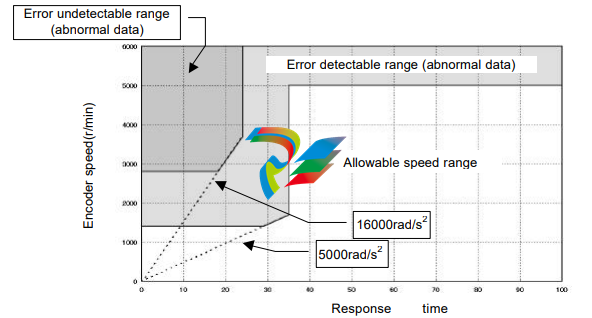
u Allowable encoder (motor) speed in energy-saving mode
The limit of an encoder (a motor) speed is 5,000r/min. The [alarm 55: ABS multi-turn data error] occurs if
the encoder rotates at more than the limited speed, and a correct absolute pulse train of the multi-turn
counter may not obtained. Moreover, there are additional limits during motor acceleration duration as
shown the figure below
u Notice at power on If power is turned on while the motor rotates at 2800r/min or more, the [Alarm 55] may occur. In spite of the alarm, the multi-turn counter works normal. u ABS (multi-turn) data clear signal (CN2-11: ABS-CLEAR) The ABS (multi-turn) data clear signal should be inputted at: (a) the initial power supply, and; (b) wasting about 30 minutes or more for exchanging the built-in battery. At either case, the multi-turn counter does not keep any data. To recover from the problem, move the actuator to a proper origin and input the [ABS (multi-turn) data clear signal] at least four seconds to clear the multi-turn counter to zero. However, the single-turn encoder keeps its resolvable position during above-mentioned operation firmly. During exchanging the battery, the built-in condenser helps the multi-turn counter to keep its count at least about 30 minutes with charged energy in the condenser. Therefore, the operation of inputting [ABS (multi-turn) data clear signal] is not required before discharging the energy. Though the [alarm 50: encoder failure] may occur at power ON operation after exchanging the battery, the encoder system is normal. To recover the problem, shut off the power once and turn it on again. u Acquisition of absolute pulse trains generated by absolute encoder system The HA-655 driver provides two selectable acquisition methods of absolute pulse trains generated by the absolute encoder system; from I/O ports and from CN3 port (RS-232C). (a) Acquisition from I/O ports (CN2-44, -45 and CN2-46, -47) Acquiring an absolute pulse train An absolute pulse train of an absolute encoder system is a combination of an absolute code (13 bits) of the multi-turn counter expressing an encoder’s revolution number from its origin, and an absolute code (13 bits) of the single-turn encoder expressing a resolvable position of the encoder (the motor). Incremental signal trains following to the absolute pulse train of an absolute encoder system may be used for monitoring signals of operating condition of the motor. As a rule, acquiring an absolute pulse train is possible only one time during power ON procedure illustrated below. If acquiring an absolute pulse train is required at another timing, use the CN3 port for acquiring while the motor is stopping.
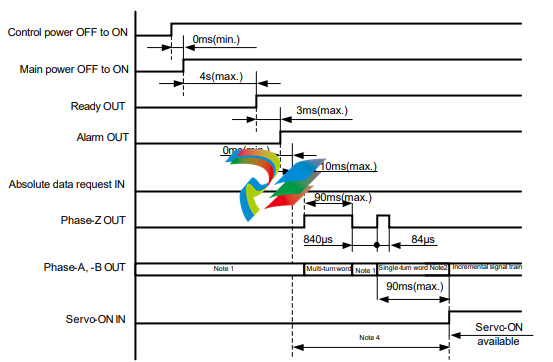
Note 1: Both output signals of phase-A and phase-B are settled at LOW-level. To settle at LOW-level, at
least three pulses are outputted. Make a sequence for the host device ignoring outputted pulses while the
phase-Z is LOW-level before generating an absolute pulse train, and during other LOW-level duration of
the phase-Z signal.
Note 2: An absolute pulse train for single-turn encoder is outputted after around 1 ms of outputting
phase-Z signal.
Note 3: The servo-ON signal is unaccepted until completing the transmission of a set of absolute pulse
trains by the [absolute data request] signal.
Note 4: The [alarm 57] occurs if the single-turn encoder rotates more than 127 resolvable position while
the multi-turn counter is transmitting an absolute pulse train.
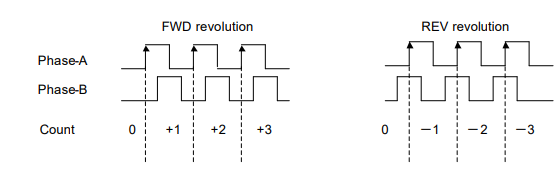
Acquiring multi-turn count
For FWD revolution of the encoder (motor), the phase-A signal has 90 degree phase shift against
phase-B signal, and for REV revolution the phase-A signal has 90 degree phase delay against phase-B
signal as shown below.
Increasing or decreasing the multi-turn counter of the host device should be discriminated by the phase
shift or delay of phase-A against phase-B. Acquire the signal at rising edge of the signal
For FWD revolution of the encoder (motor), the phase-A signal has 90 degree phase shift against
phase-B signal, and for REV revolution the phase-A signal has 90 degree phase delay against phase-B
signal as shown below.
-
 Beckhoff PLC module CX1020-0000 Basic CPU module (service phase)
 -
 Beckhoff CP7812-1056-0010 15" Multitouch Display Control Panel
 -
 Beckhoff CX5120-0115 /2GB Controller Module
 -
 Beckhoff CP7201-1000-0000 Industrial Panel PC
 -
 Beckhoff Servo Motor AM8061-0JH1-0000
 -
 BECKHOFF CP6503-0001-0050 Built-in Panel PC
 -
 Beckhoff CP3919-0010 Display G190ETN01.2 19" PCT V04. Multi-touch Control Panel
 -
 Beckhoff CX5110-0112-9020/000368201 Embedded PC Intel Atom Processor
 -
 Beckhoff AX8206-0000 Dual-Axis Module
 -
Beckhoff Nail Operating Terminal CP7032-1031-0010
-
Beckhoff AM8042-0EH1-0000 Servomotor 4.10 Nm (M0), F4 (87 mm)
-
 Beckhoff EK9300 Beckhoff CPU Module
 -
Beckhoff CP3224-0020 Multitouch-Panel-PC
-
 Beckhoff CP2712-0000 12.1" 24VDC Touch Screen WMD0
 -
 BECKHOFF CX5240-0195 / 0000289234 Embedded PC 40 GB CFast Card
 -
 Beckhoff CP6932-1000-0000 Control Panel
 -
 BECKHOFF CX5120-0121 PLC Module
 -
 Beckhoff EL3218 | EtherCAT Terminal, 8-channel analog input
 -
 Beckhoff C6640-0050 | Control cabinet Industrial PC
 -
 Beckhoff Cx5130-0120/4GB Embedded-PC
 -
 BECKHOFF CX2030-0122 PLC PROCESSOR
 -
 BECKHOFF CX5020-0122 Controller Module
 -
 Beckhoff CP3915-0000 Multitouch Panel
 -
 BECKHOFF EL3014 | EtherCAT Terminal
 -
 BECKHOFF Industrial Computer c6920-1057-0030
 -
 Beckhoff CX5130-0141/4GB CX5130-0141 Embedded PC
 -
 Beckhoff C6240-1052-0040 4-086-06-3073 Industrial Computer
 -
 Beckhoff CX5140-0135 /4GB High-Performance Embedded Industrial PC
 -
 Beckhoff C6515-1001-0000 Industrial PC
 -
 Beckhoff AX5103-0000-0200 - Digital Compact Servo Drives
 -
 Beckhoff CX2030-0130-1003/4GB Basic CPU module
 -
 Beckhoff AX8620-0000 Power Supply Module
 -
 Beckhoff CX9020-0111 module with
 -
 Beckhoff EL7332 PLC Module
 -
 BECKHOFF CP7709-0001-0020 HMI
 -
 Beckhoff CX5120-0155/2GB Embedded PC
 -
 BECKHOFF CP7037-1037-0010 OPERATOR INTERFACE TOUCHSCREEN
 -
 Beckhoff EK9000 | ModbusTCP/UDP Bus Coupler
 -
 Beckhoff Touch Panel Screen CP6020 -0000-0000
 -
 Beckhoff CX2020-0121 Module FAST Shipping
 -
 Beckhoff CX2030-0125 Basic CPU Module
 -
 Beckhoff CP3918-0000 Multi-Touch 18.5" Control Panel
 -
 Automotion LC4A00010 DC BL Motor Control, ATS, Sub Assy, SCP, 115VAC,
 -
 500T-115VAC - VAS ENGINEERING - DORIC 500 SERIES DIGITAL TEMP INDICATOR
 -
 Honeywell X-DCS2000/EN Digital Integrated System Manager 50/60Hz 100-240V #4
 -
 Kollmorgen S60600 Servostar600 606-Fan 4 kVA, 6 A, 3 X 230 - 480 V
 -
 ABB XZ C828 A101 Didt Dioder Snubber 3BHE039453R0101
 -
 ABB 3BHB027232R0001 1-Phase Charging Transformer
 -
 ABB 3BHE006412R0101 Circuit Board UFC762AE101
 -
 ABB XVC770BE101 3BHE021083R0101 Circuit Board
 -
 ABB 3BHE021887R0101 (Model: UBCC717BE101 / UBC717BE101) is an advanced
 -
 ABB 3BHE032593R0001 Isolated Power Supply
 -
 ABB 3BSC610023R0001 POWER SUPPLY SD812
 -
 Beckhoff C6650-0060 | Control cabinet Industrial PC
 -
 Beckhoff CP2916-0000 Industrial HMI Display Panel
 -
 Beckhoff AM8053-0L2B-0000 Servomotor 15.4 Nm (M0), F5 (104 mm)
 -
 Beckhoff CP6202-0001-0020 Industrial Panel PC
 -
Beckhoff CX2020-0120 Plc Module
-
 Beckhoff CX1010-0111 BASIC CPU MODULE
 -
 Beckhoff C6017-0010 | Ultra-compact Industrial PC
 -
 BECKHOFF CX2040-0155 Plc Module
 -
 Beckhoff CX5120-0125 Embedded PC
 -
 BECKHOFF C6930-0040 INDUSTRIAL CONTROL COMPUTER
 -
 Beckhoff CP6907-0001-0000 Economy Built-in Control Panel
 -
 Beckhoff CP2912-0000 Multi-Touch Built-In Control Panel
 -
 Beckhoff C6015-0010 Ultra-Compact Industrial PC
 -
 Beckhoff CX5130 | Embedded PC with Intel Atom® E3827
 -
 Beckhoff C6030-0060 Ultra-Compact Industrial PC
 -
 OMRON 3G3XV-A2007 3G3XV-A2007-NEV2
 -
 Omron NJ1019000 NJ1 programable logic controller
 -
 OMRON C120-LK202-EV1/C120LK202EV1
 -
 OMRON C200H-AD003 PLC
 -
 OMRON C200H-CPU23-E COIL 24VDC PLC
 -
 Omron C200HG - C200H-ID212- C200H-OC226 C200HW-BC101 PLC Base Unit
 -
 OMRON C200H-OC222(Output Unit),C200H-PS211(Power Supply Unit),SP001 Module Rack
 -
 OMRON C200H-RT201 PROGRAMMABLE CONTROLLER
 -
 OMRON C200HS-CPU01-E SYSMAC PROGRAMMABLE CONTROLLER
 -
 OMRON C200H-SNT31 C200H Programmable Controllers
 -
 OMRON C200HW-MC402-E Motion control unit
 -
 OMRON C200PC-ISA02-DRM-E PLC ISA bus compatible board card
 -
 OMRON C500-CT012 PLC
 -
 OMRON C500-NC103-E PLC
 -
 OMRON C500-NC222-E PLC
 -
 OMRON C500-PRW05-V1 PLC
 -
 OMRON C500-PRW06 PROGRAMMABLE CONTROLLER
 -
 OMRON C500-PS223-E 3G2A5-PS223-E PLC SYSMAC PROGRAMMABLE CONTROLLER
 -
 OMRON C500-TU001 3G2A5-TU001 PLC PLC
 -
 OMRON C60H-C1DR-DE-V1 Programmable Controllers
 -
 OMRON C60H-C5DR-DE-V1 Programmable Controllers
 -
 OMRON C60H-C6DR-DE-V1 Programmable Controllers
 -
 OMRON CJ1G-CPU44H CPU module
 -
 OMRON CJ1G-CPU45H PLC
 -
 OMRON CJ1M-CPU13-ETN V4.0 PLC PLC
 -
 OMRON CJ1W-AD041-V1 Analog input uni
 -
 OMRON CJ1W-CORT21 PLC module
 -
 OMRON CJ1W-IDP01 Input unit
 -
 OMRON CJ1W-MCH71 - MECHATROLINK-II
 -
 OMRON CJ1W-MD261 Digital I/O
 -
 OMRON CJ1W-NC413 Position control unit
 -
 OMRON CJ1W-NCF71 Position Control Units
 -
 OMRON CJ1W-PTS51 Process Simulation I/O Module
 -
 OMRON CJ1W-PTS52 Process Simulation I/O Module
 -
 OMRON CJ1W-SCU21-V1 PLC
 -
 Omron CJ1W-SCU22 Serial Communication Unit
 -
 OMRON CJ1W-TC001 CJ Series Temperature Control Unit
 -
 Omron CK3W-AX1515N Motion Controller
 -
 Omron CP1E-N60DR-D Compact PLC CPU
 -
 OMRON CP1E-NA20DT1-D PLC PLC
 -
 OMRON CP1H-X40DT-D plc PLC
 -
 OMRON CPM2C-S110C-DRT Interface module
 -
 OMRON CQM1-AD041 PLC
 -
 SAACKE F‑GDSA‑1 / F‑GDSA‑2 Feuerungsautomaten
 -
 SAACKE F-GDSA 143303 Controller SHIPS UPS
 -
 ICS Triplex T8270 Trusted 24 Vdc FanAssembly
 -
 SCHNEIDER M522220000 SA SM_DO16R 16 DIGITAL OUTPUTS MODULE
 -
 LENZ EPL10200-W EPZ-10203 CANPT010W3E
 -
 OMRON CQM1H-ADB21 PLC
 -
OMRON CQM1H-CPU61 PLC
-
 OMRON CQM1H-MAB42 PLC
 -
 OMRON CQM1-TC102 CQM1-TC101 PLC
 -
 OMRON CS1G-CPU44-EV1 PLC
 -
 OMRON CS1G-CPU44H CPU
 -
OMRON CS1H-CPU63-EV1 PLC
-
 OMRON CS1H-CPU66-V1 PLC
 -
 OMRON CS1W-CLK13 PLC communication module
 -
OMRON CS1W-EIP21 PLC
-
 OMRON CS1W-MAD44 PLC PLC
 -
 OMRON CS1W-SCU31-V1 CVM1-BC103 PLC


