
HarmonicHarmonic Drive™ servo
Increasing or decreasing the single-turn encoder counter of the host device should be discriminated by
the phase shift or delay of phase-A against phase-B. Acquire the signal at rising and falling edge of the
signal.
An example of signal transmission
The following is an example of the multi-turn count: 8, single-turn encoder count: 25 and an incremental
pulse train at a usual operation.
The actual resolvable position of the encoder (motor) can obtained by the calculation of:
(b) Acquiring from CN3 port (RS-232C)
Connecter specifications
Connect an RS-232C cable having following specifications between the CN3 port of the HA-655 driver
and a RS-232C port of a host device.
Connecters: D-sub connecter having 9 female pins
Pin assignments:
Sending a command to HA-655 driver (host →HA-655)
The command should be 10 characters in length including a delimiter as illustrated below. The
HA-655 driver waits until receiving 10 characters without any processing. Make sure that the
message has 10 characters including a delimiter.
(1) The first function of the [position control block] is the [error count] calculation by the [error counter]
in the block subtracting a feedback count from a command count.
(2) The second function is the block that converts the [error count] to a [speed command] multiplying a
factor, and then transmits the [speed command] to the [speed control block]. The factor (Kp) is
called [position loop gain].
It is clear in the formula that a large [error pulse] is converted into a high [speed command] and a
zero pulse into a zero speed command, in other words, a stop command.
(3) If the [position loop gain (Kp)] is high, a small [error count] is converted into a higher [speed
command]. That is to say, higher gain provides the servo system with better response.
However, very high gain commands result in high [speed commands] from very minimal [error
count] which will result in overshooting. To compensate for the overshoot the [position control block]
generates a high speed reverse command, then overshoots in the opposite direction * * * finally
hunting motion may take place.
Conversely, if the [position loop gain (Kp)] is very low, you will get very slow positioning motion
(undershoot), and a poor servo response.
(4) In conclusion, it is important to set the optimum value to the [position loop gain (Kp)]. The HA-655
driver has been set with the most suitable value for general applications as a factory default. If the
load inertia is very heavy and the default is not suitable, tune it carefully.
◆ [Speed control block], [speed loop gain], and [speed loop integral compensation]
(1) The first function of the [speed control block] is to subtract a feedback signal from a command
signal.
(2) The second function is the block converts the difference to a [current command] multiplies it by a
factor, and then transmits the [current command (I)] to the [power amplifier]. The factor (Kv) is
called [speed loop gain].
It is clear in the formula that a significant [speed difference] is converted into a high [current
command] and zero difference into zero current command, in other words, a stop command.
(3) Just as with the [position loop gain], higher gain provides better response and excessive gain
results in hunting. Low gain requires no hunting but raises the occurrence of undershoots.
(4) The [speed loop integral compensation (Tv)] of The HA-655 driver makes less influence on load
fluctuation.
If the [speed loop integral compensation (Tv)] is smaller, the speed response to the load fluctuation
becomes better, but too small a value results in hunting. Excessive compensation requires no
hunting, but will result in a poor response for load fluctuation.
● Tuning method
[Tune mode]→[0.speed loop gain], and [1: speed loop integral compensation]
◆ Feed forward gain
(1) In the position mode The HA-655 driver controls the error count, (the difference between
[command pulse] and [feedback pulse]), to be [0]. At the beginning of inputting a command pulse
train, the actuator starts slowly because of small error count.
(2) The [feed forward] function may accelerate the actuator as much as possible, adding speed pulses
converted from the command pulse frequency directly to the driver’s speed control loop
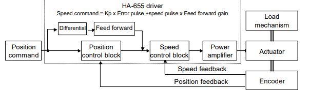
) The relation between the feed forward and actuator motion is as follows:
Higher feeding allows for better following to command, but excessive feeding results in hunting and
erratic motion.
Low feeding requires no hunting but a poor following of the command.
● Tuning method
[Tune mode]→[3:Feed forward]
2-2-5 FWD inhibit and REV inhibit
The HA-655 driver provides [FWD inhibit] and [REV inhibit] input signal ports.
[FWD inhibit]: opening (OFF) the input inhibits forward rotation.
[REV inhibit]: opening (OFF) the input inhibits reverse rotation.
Opening (OFF) both inputs inhibits all rotation.
The inputs may be used to limit the motion range between limit sensors.
2-2-6 In-position
In the position mode, even though the driver controls the actuator to make the [error count 0], it is not
-
 Beckhoff PLC module CX1020-0000 Basic CPU module (service phase)
 -
 Beckhoff CP7812-1056-0010 15" Multitouch Display Control Panel
 -
 Beckhoff CX5120-0115 /2GB Controller Module
 -
 Beckhoff CP7201-1000-0000 Industrial Panel PC
 -
 Beckhoff Servo Motor AM8061-0JH1-0000
 -
 BECKHOFF CP6503-0001-0050 Built-in Panel PC
 -
 Beckhoff CP3919-0010 Display G190ETN01.2 19" PCT V04. Multi-touch Control Panel
 -
 Beckhoff CX5110-0112-9020/000368201 Embedded PC Intel Atom Processor
 -
 Beckhoff AX8206-0000 Dual-Axis Module
 -
Beckhoff Nail Operating Terminal CP7032-1031-0010
-
Beckhoff AM8042-0EH1-0000 Servomotor 4.10 Nm (M0), F4 (87 mm)
-
 Beckhoff EK9300 Beckhoff CPU Module
 -
Beckhoff CP3224-0020 Multitouch-Panel-PC
-
 Beckhoff CP2712-0000 12.1" 24VDC Touch Screen WMD0
 -
 BECKHOFF CX5240-0195 / 0000289234 Embedded PC 40 GB CFast Card
 -
 Beckhoff CP6932-1000-0000 Control Panel
 -
 BECKHOFF CX5120-0121 PLC Module
 -
 Beckhoff EL3218 | EtherCAT Terminal, 8-channel analog input
 -
 Beckhoff C6640-0050 | Control cabinet Industrial PC
 -
 Beckhoff Cx5130-0120/4GB Embedded-PC
 -
 BECKHOFF CX2030-0122 PLC PROCESSOR
 -
 BECKHOFF CX5020-0122 Controller Module
 -
 Beckhoff CP3915-0000 Multitouch Panel
 -
 BECKHOFF EL3014 | EtherCAT Terminal
 -
 BECKHOFF Industrial Computer c6920-1057-0030
 -
 Beckhoff CX5130-0141/4GB CX5130-0141 Embedded PC
 -
 Beckhoff C6240-1052-0040 4-086-06-3073 Industrial Computer
 -
 Beckhoff CX5140-0135 /4GB High-Performance Embedded Industrial PC
 -
 Beckhoff C6515-1001-0000 Industrial PC
 -
 Beckhoff AX5103-0000-0200 - Digital Compact Servo Drives
 -
 Beckhoff CX2030-0130-1003/4GB Basic CPU module
 -
 Beckhoff AX8620-0000 Power Supply Module
 -
 Beckhoff CX9020-0111 module with
 -
 Beckhoff EL7332 PLC Module
 -
 BECKHOFF CP7709-0001-0020 HMI
 -
 Beckhoff CX5120-0155/2GB Embedded PC
 -
 BECKHOFF CP7037-1037-0010 OPERATOR INTERFACE TOUCHSCREEN
 -
 Beckhoff EK9000 | ModbusTCP/UDP Bus Coupler
 -
 Beckhoff Touch Panel Screen CP6020 -0000-0000
 -
 Beckhoff CX2020-0121 Module FAST Shipping
 -
 Beckhoff CX2030-0125 Basic CPU Module
 -
 Beckhoff CP3918-0000 Multi-Touch 18.5" Control Panel
 -
 Automotion LC4A00010 DC BL Motor Control, ATS, Sub Assy, SCP, 115VAC,
 -
 500T-115VAC - VAS ENGINEERING - DORIC 500 SERIES DIGITAL TEMP INDICATOR
 -
 Honeywell X-DCS2000/EN Digital Integrated System Manager 50/60Hz 100-240V #4
 -
 Kollmorgen S60600 Servostar600 606-Fan 4 kVA, 6 A, 3 X 230 - 480 V
 -
 ABB XZ C828 A101 Didt Dioder Snubber 3BHE039453R0101
 -
 ABB 3BHB027232R0001 1-Phase Charging Transformer
 -
 ABB 3BHE006412R0101 Circuit Board UFC762AE101
 -
 ABB XVC770BE101 3BHE021083R0101 Circuit Board
 -
 ABB 3BHE021887R0101 (Model: UBCC717BE101 / UBC717BE101) is an advanced
 -
 ABB 3BHE032593R0001 Isolated Power Supply
 -
 ABB 3BSC610023R0001 POWER SUPPLY SD812
 -
 Beckhoff C6650-0060 | Control cabinet Industrial PC
 -
 Beckhoff CP2916-0000 Industrial HMI Display Panel
 -
 Beckhoff AM8053-0L2B-0000 Servomotor 15.4 Nm (M0), F5 (104 mm)
 -
 Beckhoff CP6202-0001-0020 Industrial Panel PC
 -
Beckhoff CX2020-0120 Plc Module
-
 Beckhoff CX1010-0111 BASIC CPU MODULE
 -
 Beckhoff C6017-0010 | Ultra-compact Industrial PC
 -
 BECKHOFF CX2040-0155 Plc Module
 -
 Beckhoff CX5120-0125 Embedded PC
 -
 BECKHOFF C6930-0040 INDUSTRIAL CONTROL COMPUTER
 -
 Beckhoff CP6907-0001-0000 Economy Built-in Control Panel
 -
 Beckhoff CP2912-0000 Multi-Touch Built-In Control Panel
 -
 Beckhoff C6015-0010 Ultra-Compact Industrial PC
 -
 Beckhoff CX5130 | Embedded PC with Intel Atom® E3827
 -
 Beckhoff C6030-0060 Ultra-Compact Industrial PC
 -
 OMRON 3G3XV-A2007 3G3XV-A2007-NEV2
 -
 Omron NJ1019000 NJ1 programable logic controller
 -
 OMRON C120-LK202-EV1/C120LK202EV1
 -
 OMRON C200H-AD003 PLC
 -
 OMRON C200H-CPU23-E COIL 24VDC PLC
 -
 Omron C200HG - C200H-ID212- C200H-OC226 C200HW-BC101 PLC Base Unit
 -
 OMRON C200H-OC222(Output Unit),C200H-PS211(Power Supply Unit),SP001 Module Rack
 -
 OMRON C200H-RT201 PROGRAMMABLE CONTROLLER
 -
 OMRON C200HS-CPU01-E SYSMAC PROGRAMMABLE CONTROLLER
 -
 OMRON C200H-SNT31 C200H Programmable Controllers
 -
 OMRON C200HW-MC402-E Motion control unit
 -
 OMRON C200PC-ISA02-DRM-E PLC ISA bus compatible board card
 -
 OMRON C500-CT012 PLC
 -
 OMRON C500-NC103-E PLC
 -
 OMRON C500-NC222-E PLC
 -
 OMRON C500-PRW05-V1 PLC
 -
 OMRON C500-PRW06 PROGRAMMABLE CONTROLLER
 -
 OMRON C500-PS223-E 3G2A5-PS223-E PLC SYSMAC PROGRAMMABLE CONTROLLER
 -
 OMRON C500-TU001 3G2A5-TU001 PLC PLC
 -
 OMRON C60H-C1DR-DE-V1 Programmable Controllers
 -
 OMRON C60H-C5DR-DE-V1 Programmable Controllers
 -
 OMRON C60H-C6DR-DE-V1 Programmable Controllers
 -
 OMRON CJ1G-CPU44H CPU module
 -
 OMRON CJ1G-CPU45H PLC
 -
 OMRON CJ1M-CPU13-ETN V4.0 PLC PLC
 -
 OMRON CJ1W-AD041-V1 Analog input uni
 -
 OMRON CJ1W-CORT21 PLC module
 -
 OMRON CJ1W-IDP01 Input unit
 -
 OMRON CJ1W-MCH71 - MECHATROLINK-II
 -
 OMRON CJ1W-MD261 Digital I/O
 -
 OMRON CJ1W-NC413 Position control unit
 -
 OMRON CJ1W-NCF71 Position Control Units
 -
 OMRON CJ1W-PTS51 Process Simulation I/O Module
 -
 OMRON CJ1W-PTS52 Process Simulation I/O Module
 -
 OMRON CJ1W-SCU21-V1 PLC
 -
 Omron CJ1W-SCU22 Serial Communication Unit
 -
 OMRON CJ1W-TC001 CJ Series Temperature Control Unit
 -
 Omron CK3W-AX1515N Motion Controller
 -
 Omron CP1E-N60DR-D Compact PLC CPU
 -
 OMRON CP1E-NA20DT1-D PLC PLC
 -
 OMRON CP1H-X40DT-D plc PLC
 -
 OMRON CPM2C-S110C-DRT Interface module
 -
 OMRON CQM1-AD041 PLC
 -
 SAACKE F‑GDSA‑1 / F‑GDSA‑2 Feuerungsautomaten
 -
 SAACKE F-GDSA 143303 Controller SHIPS UPS
 -
 ICS Triplex T8270 Trusted 24 Vdc FanAssembly
 -
 SCHNEIDER M522220000 SA SM_DO16R 16 DIGITAL OUTPUTS MODULE
 -
 LENZ EPL10200-W EPZ-10203 CANPT010W3E
 -
 OMRON CQM1H-ADB21 PLC
 -
OMRON CQM1H-CPU61 PLC
-
 OMRON CQM1H-MAB42 PLC
 -
 OMRON CQM1-TC102 CQM1-TC101 PLC
 -
 OMRON CS1G-CPU44-EV1 PLC
 -
 OMRON CS1G-CPU44H CPU
 -
OMRON CS1H-CPU63-EV1 PLC
-
 OMRON CS1H-CPU66-V1 PLC
 -
 OMRON CS1W-CLK13 PLC communication module
 -
OMRON CS1W-EIP21 PLC
-
 OMRON CS1W-MAD44 PLC PLC
 -
 OMRON CS1W-SCU31-V1 CVM1-BC103 PLC


