HarmonicHarmonic Drive™ servo
always possible due to the influence of external forces, acceleration, and deceleration. Establishing a
positioning allowance is a good solution to the problem; that is [in-position range].
[Tune mode]→[4: in-position range] sets the allowance. The actuator position comes within the range
calculated with the formula below, the [CN2-33: in-position] signal outputted.
2-3 Speed mode
The HA-655 driver makes use of either the position control or the speed control. This section describes
the speed mode. (※ The default setting is the [position mode].
Before running, set the control mode by [parameter mode] → [0: control mode].
2-3-1 Speed conversion factor
In the speed mode, the command is sent from a host with an analog voltage signal. The [speed
conversion factor] converts the [speed command] voltage to motor speed.
The [speed conversion factor] is the motor speed when the [speed command voltage] is [10V]. The
actual motor speed is obtained by the following formula:
The [speed monitor] (SPD-MON: CN2-23pin) output voltage as follows:
● Setting
[Parameter mode]→[9: speed conversion factor]
2-3-2 Voltage of speed command
Input the voltage converted by the [speed conversion factor] into [CN2-31: speed command] and
[CN2-32: speed command common] pins. The [speed command voltage] is obtained by [parameter
mode]→[9: speed conversion factor].
◆ FWD enable and REV enable
The HA-655 driver provides [FWD enable] and [REV enable] input ports. The rotary direction of the
actuator is decided by the polarity of [CN2-31: speed command SPD-CMD] and ON/OFF states of [FWD
enable] and [REV enable] as shown in the table below:
CN2-31 Speed cmd.: SPD-CMD +Command -Command
CN2-4 FWD enable: FWD-EN ON OFF ON OFF
CN2-5 REV enable: ON Zero clamp, zero speed REV rotation Zero clamp, zero speed FWD rotation
REV-EN OFF FWD rotation Zero clamp, zero speed REV rotation Zero clamp, zero speed
● Relating input pins
CN2-31: speed command, CN2-32: speed command common, CN2-4: FWD enable,CN2-5:REV enable
◆ Speed command offset
In the speed mode, the motor may rotate slightly in spite of a [0V] speed command voltage. This problem
may occur when the speed command voltage has an offset of a few milli-volts. This function removes the
slight rotation compensating the command voltage offset.
While inputting a [OV] command voltage adjust the speed command offset until the actuator stops
rotating.
[Speed command automatic offset] function is also provided.
● Setting
[Tune mode]→[9: speed command offset], [test mode]→[So: Speed command automatic offset]

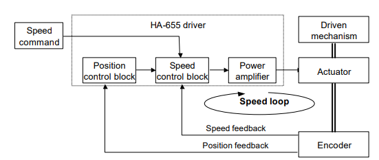
In the figure, the closed loop of [speed control block]→[power amplifier]→[actuator]→[encoder]→[speed
control block] is called [speed loop].
The details of the loop are described as follows:
◆ [Speed control block], [speed loop gain], and [speed loop integral compensation]
(1) The first function of the [speed control block] is to subtract a feedback signal from a command
signal.
(2) The second function is when the block converts the difference to a [current command] multiplies it
by a factor, and then transmits the [current command] to the [power amplifier]. The factor (Kv) is
called [speed loop gain].
It is clear in the formula that a [speed difference] is converted into a high [current command], and a
zero difference into a zero current command, in other words, a stop command.
(3) If the [speed loop gain (Kv)] is high, a small [speed command] is converted into a higher [current
command]. That is to say, higher gain provides the servo system with a better response.
However, very high gain settings can cause a very high [current command] in response to a small
[speed command] which will result in overshooting. To compensate overshooting, the [speed
control block] generates a high speed reverse command, then ・・・・・・・・・finally hunting motion
may take place.
(4) Conversely, if the [speed loop gain (Kv)] is very low, you will get very slow positioning motion
(undershoot) and poor servo response.
(5) The [speed loop integral compensation (Tv)] of the HA-655 driver minimizes the influence of load
fluctuation.
If the [speed loop integral compensation (Tv)] is low, the speed response to the load fluctuation
becomes better, but very small value can result in hunting. Excessive compensation requires no
hunting but a poor response for load fluctuation.
● Setting
[Tune mode]→[0: speed loop gain], [1: speed loop integral compensation]
2-3-4 Command change
The function can operate the actuator without command at the speed specified by [tune mode]→[6:
internal speed command]. This is convenient for diagnosis and for test operation without hosts.
The actuator will rotate at the speed set by the [internal speed command] when a signal is input to
CMD-CHG (CN2-6) and stops when the signal is removed.
● Relating I/O pin
Input pin: CN2-6
2-3-5 Acceleration / deceleration time constants
[Acceleration time constant] is the time it takes to accelerate the motor from [0 r/min] to the speed of [A:
speed limit] of [parameter mode].
[Deceleration time constant] is the time it takes to decelerate the motor from the speed of [A: speed limit]


.png)


.png)


.png)


