
HarmonicHarmonic Drive™ servo
(1) 2-pulse train (FWD and REV pulse train)
Two pairs of two terminals are provided, and each of FWD and REV pulse trains is assigned a pair
independently. FWD commands and REV commands are inputted in the pair of FWD ports and REV
ports respectively, as shown in the figure below. When signals are inputted to a pair of terminals, the
signal to the other should keep [OFF] state.
(2) 1-pulse train (polarity + pulse train)
One pair of terminals is assigned dedicatedly for command pulse train, and the other is assigned to a
sign for rotary direction. Position commands are inputted in the FWD port pair only and the REV port pair
accepts the sign of rotary direction, as shown in the figure below. [OFF] or [Low level] state is for the
FWD command and [ON] or [High] level is for the REV command.
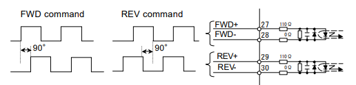
2-phase pulse train (A-B phase pulses with 90 degree difference)
Both port pairs receive the command pulse trains that have a 90 electric degree difference relative to
each other as shown in the figure below. For the FWD command, the pulse train to the FWD ports
advances 90 degrees from the REV port train. For the REV command, the REV port train advances from
the FWD port train.
The encoder pulse trains to the driver have this 2-phase pulse configuration
◆ Multiplication of command
When the command configuration is a
[2-phase pulse] type, it is possible to multiply
the command pulse train by 2 or 4 for the
command pulse train to an actuator.
The encoder feedback pulse train is
quadrupled.
● Setting
[Parameter mode] → [2: multiplication of
2-phase pulse]
◆ Electronic gear
The electronic gear function can be set make a given
displacement of the driven mechanism for one
command pulse, an integer, or a convenient number.
For example, it is convenient to set the displacement of
0.1 micrometer for one pulse as shown in figure to the
right.
The function multiples the command pulse count by the
coefficient (fraction).
The relation of [denominator / numerator] of the coefficient
is obtained as follows:
2-2-2 Command transmitting system
Two systems are provided for transmitting command pulses: [open collector] and [line driver].
◆ Open collector system
This system employs a transistor whose emitter is
common and whose collector is open. Since the
output signal is voltage type, this system is
unsuitable for long distance transmission due to line
voltage drop.
◆ Line driver system
The line driver system conforms to (EIA) RS-422
standard providing line drivers for transmitting
signal pulses. Since the output signal is current type,
this system is suitable for long distance
transmissions without attenuation of signals.
Furthermore, the line driver system transmits data
faster than the open collector system.
2-2-3 Outputting encoder signals
Two kinds of encoder are selectable for the FHA-C
series actuator: incremental or absolute. The
incremental encoder feeds back two pulse-trains
into the HA-655 driver as shown in the figure to the
right. The pulse trains are called [phase-A] and
[phase-B]. For the encoder resolution, refer to
actuator’s technical manual.
On the other hand, the absolute encoder feeds back
a combination of absolute signals and two
pulse-train signals.
In addition to the 2-phase pulse trains, both
encoders output a [phase-Z] pulse signal once per
motor rotation for use as an origin. The pulse signal
is sometimes called [phase-C] or [index].
The HA-655 driver outputs encoder signals using a
line driver system. The signals can be received by a
line receiver: AM26LS32 (EIA-422A) or equivalent.
Phase-Z signal is also available (open collector
output {CN-42 pin}).
The phase-Z signal is asynchronous.
Three encoder signals mentioned above are
available for a host.
● Relating I/O pins
Output pins: CN2-42 to 49
2-2-4 Absolute encoder signals
u General descriptions and functions of absolute encoders
The absolute encoder housed in a FHA-C series actuator provides an absolute sensor to generate an
absolute pulse train for a resolvable position (the sensor is herein after referred to as “single-turn
encoder”.), and an electronic counter to generate an absolute pulse train for a revolution of the motor
(the counter is hereinafter referred to as “multi-turn counter”.).
An absolute position of the encoder is kept in the memory, which is always energized by a combination
of the built-in condenser in the actuator and the backup battery housed in the HA-655 driver.
Please interpret that “single-turn” and “multi-turn” in the manual mean one and plural revolutions of the
encoder (the motor) in an actuator, respectively. Therefore, the actual actuator resolvable position of
either “single-turn” or “multi-turn” can be obtained by multiplying an absolute pulse train of the single-turn
encoder and the multi-turn counter by a reduction ratio of the actuator.
u Single-turn absolute encoder
The single-turn encoder is composed of an encoder disk, an LED light source, and a photo-detector. The
single-turn absolute encoder system outputs a current absolute pulse train combined with an absolute
-
 Beckhoff PLC module CX1020-0000 Basic CPU module (service phase)
 -
 Beckhoff CP7812-1056-0010 15" Multitouch Display Control Panel
 -
 Beckhoff CX5120-0115 /2GB Controller Module
 -
 Beckhoff CP7201-1000-0000 Industrial Panel PC
 -
 Beckhoff Servo Motor AM8061-0JH1-0000
 -
 BECKHOFF CP6503-0001-0050 Built-in Panel PC
 -
 Beckhoff CP3919-0010 Display G190ETN01.2 19" PCT V04. Multi-touch Control Panel
 -
 Beckhoff CX5110-0112-9020/000368201 Embedded PC Intel Atom Processor
 -
 Beckhoff AX8206-0000 Dual-Axis Module
 -
Beckhoff Nail Operating Terminal CP7032-1031-0010
-
Beckhoff AM8042-0EH1-0000 Servomotor 4.10 Nm (M0), F4 (87 mm)
-
 Beckhoff EK9300 Beckhoff CPU Module
 -
Beckhoff CP3224-0020 Multitouch-Panel-PC
-
 Beckhoff CP2712-0000 12.1" 24VDC Touch Screen WMD0
 -
 BECKHOFF CX5240-0195 / 0000289234 Embedded PC 40 GB CFast Card
 -
 Beckhoff CP6932-1000-0000 Control Panel
 -
 BECKHOFF CX5120-0121 PLC Module
 -
 Beckhoff EL3218 | EtherCAT Terminal, 8-channel analog input
 -
 Beckhoff C6640-0050 | Control cabinet Industrial PC
 -
 Beckhoff Cx5130-0120/4GB Embedded-PC
 -
 BECKHOFF CX2030-0122 PLC PROCESSOR
 -
 BECKHOFF CX5020-0122 Controller Module
 -
 Beckhoff CP3915-0000 Multitouch Panel
 -
 BECKHOFF EL3014 | EtherCAT Terminal
 -
 BECKHOFF Industrial Computer c6920-1057-0030
 -
 Beckhoff CX5130-0141/4GB CX5130-0141 Embedded PC
 -
 Beckhoff C6240-1052-0040 4-086-06-3073 Industrial Computer
 -
 Beckhoff CX5140-0135 /4GB High-Performance Embedded Industrial PC
 -
 Beckhoff C6515-1001-0000 Industrial PC
 -
 Beckhoff AX5103-0000-0200 - Digital Compact Servo Drives
 -
 Beckhoff CX2030-0130-1003/4GB Basic CPU module
 -
 Beckhoff AX8620-0000 Power Supply Module
 -
 Beckhoff CX9020-0111 module with
 -
 Beckhoff EL7332 PLC Module
 -
 BECKHOFF CP7709-0001-0020 HMI
 -
 Beckhoff CX5120-0155/2GB Embedded PC
 -
 BECKHOFF CP7037-1037-0010 OPERATOR INTERFACE TOUCHSCREEN
 -
 Beckhoff EK9000 | ModbusTCP/UDP Bus Coupler
 -
 Beckhoff Touch Panel Screen CP6020 -0000-0000
 -
 Beckhoff CX2020-0121 Module FAST Shipping
 -
 Beckhoff CX2030-0125 Basic CPU Module
 -
 Beckhoff CP3918-0000 Multi-Touch 18.5" Control Panel
 -
 Automotion LC4A00010 DC BL Motor Control, ATS, Sub Assy, SCP, 115VAC,
 -
 500T-115VAC - VAS ENGINEERING - DORIC 500 SERIES DIGITAL TEMP INDICATOR
 -
 Honeywell X-DCS2000/EN Digital Integrated System Manager 50/60Hz 100-240V #4
 -
 Kollmorgen S60600 Servostar600 606-Fan 4 kVA, 6 A, 3 X 230 - 480 V
 -
 ABB XZ C828 A101 Didt Dioder Snubber 3BHE039453R0101
 -
 ABB 3BHB027232R0001 1-Phase Charging Transformer
 -
 ABB 3BHE006412R0101 Circuit Board UFC762AE101
 -
 ABB XVC770BE101 3BHE021083R0101 Circuit Board
 -
 ABB 3BHE021887R0101 (Model: UBCC717BE101 / UBC717BE101) is an advanced
 -
 ABB 3BHE032593R0001 Isolated Power Supply
 -
 ABB 3BSC610023R0001 POWER SUPPLY SD812
 -
 Beckhoff C6650-0060 | Control cabinet Industrial PC
 -
 Beckhoff CP2916-0000 Industrial HMI Display Panel
 -
 Beckhoff AM8053-0L2B-0000 Servomotor 15.4 Nm (M0), F5 (104 mm)
 -
 Beckhoff CP6202-0001-0020 Industrial Panel PC
 -
Beckhoff CX2020-0120 Plc Module
-
 Beckhoff CX1010-0111 BASIC CPU MODULE
 -
 Beckhoff C6017-0010 | Ultra-compact Industrial PC
 -
 BECKHOFF CX2040-0155 Plc Module
 -
 Beckhoff CX5120-0125 Embedded PC
 -
 BECKHOFF C6930-0040 INDUSTRIAL CONTROL COMPUTER
 -
 Beckhoff CP6907-0001-0000 Economy Built-in Control Panel
 -
 Beckhoff CP2912-0000 Multi-Touch Built-In Control Panel
 -
 Beckhoff C6015-0010 Ultra-Compact Industrial PC
 -
 Beckhoff CX5130 | Embedded PC with Intel Atom® E3827
 -
 Beckhoff C6030-0060 Ultra-Compact Industrial PC
 -
 OMRON 3G3XV-A2007 3G3XV-A2007-NEV2
 -
 Omron NJ1019000 NJ1 programable logic controller
 -
 OMRON C120-LK202-EV1/C120LK202EV1
 -
 OMRON C200H-AD003 PLC
 -
 OMRON C200H-CPU23-E COIL 24VDC PLC
 -
 Omron C200HG - C200H-ID212- C200H-OC226 C200HW-BC101 PLC Base Unit
 -
 OMRON C200H-OC222(Output Unit),C200H-PS211(Power Supply Unit),SP001 Module Rack
 -
 OMRON C200H-RT201 PROGRAMMABLE CONTROLLER
 -
 OMRON C200HS-CPU01-E SYSMAC PROGRAMMABLE CONTROLLER
 -
 OMRON C200H-SNT31 C200H Programmable Controllers
 -
 OMRON C200HW-MC402-E Motion control unit
 -
 OMRON C200PC-ISA02-DRM-E PLC ISA bus compatible board card
 -
 OMRON C500-CT012 PLC
 -
 OMRON C500-NC103-E PLC
 -
 OMRON C500-NC222-E PLC
 -
 OMRON C500-PRW05-V1 PLC
 -
 OMRON C500-PRW06 PROGRAMMABLE CONTROLLER
 -
 OMRON C500-PS223-E 3G2A5-PS223-E PLC SYSMAC PROGRAMMABLE CONTROLLER
 -
 OMRON C500-TU001 3G2A5-TU001 PLC PLC
 -
 OMRON C60H-C1DR-DE-V1 Programmable Controllers
 -
 OMRON C60H-C5DR-DE-V1 Programmable Controllers
 -
 OMRON C60H-C6DR-DE-V1 Programmable Controllers
 -
 OMRON CJ1G-CPU44H CPU module
 -
 OMRON CJ1G-CPU45H PLC
 -
 OMRON CJ1M-CPU13-ETN V4.0 PLC PLC
 -
 OMRON CJ1W-AD041-V1 Analog input uni
 -
 OMRON CJ1W-CORT21 PLC module
 -
 OMRON CJ1W-IDP01 Input unit
 -
 OMRON CJ1W-MCH71 - MECHATROLINK-II
 -
 OMRON CJ1W-MD261 Digital I/O
 -
 OMRON CJ1W-NC413 Position control unit
 -
 OMRON CJ1W-NCF71 Position Control Units
 -
 OMRON CJ1W-PTS51 Process Simulation I/O Module
 -
 OMRON CJ1W-PTS52 Process Simulation I/O Module
 -
 OMRON CJ1W-SCU21-V1 PLC
 -
 Omron CJ1W-SCU22 Serial Communication Unit
 -
 OMRON CJ1W-TC001 CJ Series Temperature Control Unit
 -
 Omron CK3W-AX1515N Motion Controller
 -
 Omron CP1E-N60DR-D Compact PLC CPU
 -
 OMRON CP1E-NA20DT1-D PLC PLC
 -
 OMRON CP1H-X40DT-D plc PLC
 -
 OMRON CPM2C-S110C-DRT Interface module
 -
 OMRON CQM1-AD041 PLC
 -
 SAACKE F‑GDSA‑1 / F‑GDSA‑2 Feuerungsautomaten
 -
 SAACKE F-GDSA 143303 Controller SHIPS UPS
 -
 ICS Triplex T8270 Trusted 24 Vdc FanAssembly
 -
 SCHNEIDER M522220000 SA SM_DO16R 16 DIGITAL OUTPUTS MODULE
 -
 LENZ EPL10200-W EPZ-10203 CANPT010W3E
 -
 OMRON CQM1H-ADB21 PLC
 -
OMRON CQM1H-CPU61 PLC
-
 OMRON CQM1H-MAB42 PLC
 -
 OMRON CQM1-TC102 CQM1-TC101 PLC
 -
 OMRON CS1G-CPU44-EV1 PLC
 -
 OMRON CS1G-CPU44H CPU
 -
OMRON CS1H-CPU63-EV1 PLC
-
 OMRON CS1H-CPU66-V1 PLC
 -
 OMRON CS1W-CLK13 PLC communication module
 -
OMRON CS1W-EIP21 PLC
-
 OMRON CS1W-MAD44 PLC PLC
 -
 OMRON CS1W-SCU31-V1 CVM1-BC103 PLC


