
ABBDCS800 Hardware Manual DCS800 Drives (20 to 5200 A)
What this chapter contains
This chapter contains the safety instructions which you must follow when installing,
operating and servicing the drive. If ignored, physical injury or death may follow, or
damage may occur to the drive, the motor or driven equipment. Read the safety
instructions before you work on the unit.
To which products this chapter applies
The information is valid for the whole range of the product DCS800, the converter
modules DCS800-S0x size D1 to D7, field exciter units DCF80x, etc. like the Rebuild
Kit DCS800-R00-9xxx.
Use of warnings and notes
There are two types of safety instructions throughout this manual: warnings and
notes. Warnings caution you about conditions which can result in serious injury or
death and/or damage to the equipment. They also tell you how to avoid the danger.
Notes draw attention to a particular condition or fact, or give information on a
subject. The warning symbols are used as follows:
Dangerous voltage warning warns of high voltage which can cause
physical injury and/or damage to the equipment.
General danger warning warns about conditions, other than those
caused by electricity, which can result in physical injury or death and/or
damage to the equipment.
Electrostatic sensitive discharge warning warns of electrostatic
discharge which can damage the equipment.
Installation and maintenance work
These warnings are intended for all who work on the drive, motor cable or motor.
Ignoring the instructions can cause physical injury or death and/or damage to the
equipment..
WARNING!
• Only qualified electricians are allowed to install and maintain the drive!
• Never work on the drive, motor cable or motor when main power is applied.
Always ensure by measuring with a multimeter (impedance at least 1 Mohm)
that:
1. Voltage between drive input phases U1, V1 and W1 and the frame is
close to 0 V.
2. Voltage between terminals C+ and D- and the frame is close to 0 V.
• Do not work on the control cables when power is applied to the drive or to the
external control circuits. Externally supplied control circuits may cause
dangerous voltages inside the drive even when the main power on the drive is
switched off.
• Do not make any insulation resistance or voltage withstand tests on the drive or
drive modules.
• Isolate the motor cables from the drive when testing the insulation resistance or
voltage withstand of the cables or the motor.
• When reconnecting the motor cable, always check that the C+ and D- cables
are connected with the proper terminal.
Note:
• The motor cable terminals on the drive are at a dangerously high voltage when
the main power is on, regardless of whether the motor is running or not.
• Depending on the external wiring, dangerous voltages (115 V, 220 V or 230 V)
may be present on the relay outputs of the drive system (e.g. SDCS-IOB-2 and
RDIO).
• DCS800 with enclosure extension: Before working on the drive, isolate the
whole drive from the supply
Grounding
These instructions are intended for all who are responsible for the grounding of the
drive. Incorrect grounding can cause physical injury, death and/or equipment
malfunction and increase electromagnetic interference.
WARNING!
• Ground the drive, motor and adjoining equipment to ensure personnel safety in
all circumstances, and to reduce electromagnetic emission and pick-up.
• Make sure that grounding conductors are adequately sized and marked as
required by safety regulations.
• In a multiple-drive installation, connect each drive separately to protective
earth (PE ).
• Minimize EMC emission and make a 360° high frequency grounding (e.g.
conductive sleeves) of screened cable entries at the cabinet lead-through
plate.
• Do not install a drive equipped with an EMC filter to an ungrounded power
system or a high resistance-grounded (over 30 ohms) power system.
Note:
• Power cable shields are suitable as equipment grounding conductors only
when adequately sized to meet safety regulations.
• As the normal leakage current of the drive is higher than 3.5 mA AC or 10 mA
DC (stated by EN 50178, 5.2.11.1), a fixed protective earth connection is
required.
Printed circuit boards and fiber optic cables
These instructions are intended for all who handle the circuit boards and fiber optic
cables. Ignoring the following instructions can cause damage to the equipment.
WARNING! The printed circuit boards contain components sensitive to electrostatic
discharge. Wear a grounding wrist band when handling the boards. Do not touch the
boards unnecessarily.
Use grounding strip:

ABB order no.: 3ADV050035P0001
WARNING! Handle the fiber optic cables with care. When unplugging optic cables,
always grab the connector, not the cable itself. Do not touch the ends of the fibers
with bare hands as the fiber is extremely sensitive to dirt. The minimum allowed
bend radius is 35 mm (1.4 in.).
Mechanical installation
These notes are intended for all who install the drive. Handle the unit carefully to
avoid damage and injury.
WARNING!
• DCS800 sizes D4 ... D7: The drive is heavy. Do not lift it alone. Do not lift the
unit by the front cover. Place units D4, D4+ and D5 only on their back.
DCS800 sizes D5 ... D7: The drive is heavy. Lift the drive by the lifting lugs
only. Do not tilt the unit. The unit will overturn from a tilt of about 6 degrees.
• Make sure that dust from drilling does not enter the drive when installing.
Electrically conductive dust inside the unit may cause damage or lead to
malfunction.
• Ensure sufficient cooling.
• Do not fasten the drive by riveting or welding
Operation
These warnings are intended for all who plan the operation of the drive or operate
the drive. Ignoring the instructions can cause physical injury or death and/or damage
to the equipment.
WARNING!
• Before adjusting the drive and putting it into service, make sure that the motor
and all driven equipment are suitable for operation throughout the speed range
provided by the drive. The drive can be adjusted to operate the motor at
speeds above and below the base speed.
• Do not control the motor with the disconnecting device (disconnecting mains);
instead, use the control panel keys and , or commands via the I/O
board of the drive.
• Mains connection
You can use a disconnect switch (with fuses) to disconnect the electrical
components of the drive from the mains for installation and maintenance work.
The type of disconnect switch used must be as per EN 60947-3, Class B, so as
to comply with EU regulations, or a circuit-breaker type which switches off the
load circuit by means of an auxiliary contact causing the breaker's main
contacts to open. The mains disconnect must be locked in its "OPEN" position
during any installation and maintenance work.
• EMERGENCY STOP buttons must be installed at each control desk and at all
other control panels requiring an emergency stop function. Pressing the STOP
button on the control panel of the drive will neither cause an emergency stop of
the motor, nor will the drive be disconnected from any dangerous potential.
To avoid unintentional operating states, or to shut the unit down in case of any
imminent danger according to the standards in the safety instructions it is not
sufficient to merely shut down the drive via signals "RUN", "drive OFF" or
"Emergency Stop" respectively "control panel" or "PC tool".
• Intended use
The operating instructions cannot take into consideration every possible case
of configuration, operation or maintenance. Thus, they mainly give such advice
only, which is required by qualified personnel for normal operation of the
machines and devices in industrial installations.
If in special cases the electrical machines and devices are in-tended for use in
non-industrial installations - which may require stricter safety regulations (e.g.
protection against contact by children or similar) - these additional safety
measures for the installation must be provided by the customer during
assembly.
Note:
• When the control location is not set to Local (L not shown in the status row of
the display), the stop key on the control panel will not stop the drive. To stop
the drive using the control panel, press the LOC/REM key and then the stop
key .
Chapter overview
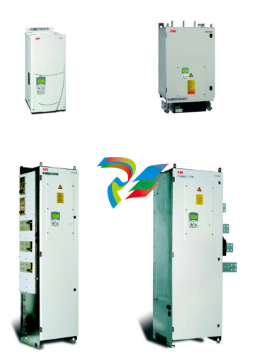
This chapter describes briefly the operating principle and construction of the
converter modules in short.
The DCS800
The DCS800-S size D1 - D7 are intended for controlling DC motors
Chapter overview
This chapter describes the mechanical installation of the DCS800.
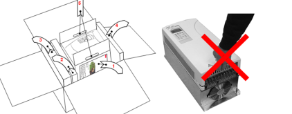
Unpacking the unit
• Open the box,
• take out shock dampers,
• separate manual and accessories.
Attention:
Do not lift the drive by the cover!
Delivery check
Check that there are no signs of damage. Before attempting installation and
operation, check the information on the nameplate of the converter module to verify
that the unit is of the correct type. The label includes an IEC rating, cULus, C-tick
(N713) and CE markings, a type code and a serial number, which allow individual
identification of each unit. The remaining digits complete the serial number so that
there are no two units with the same serial number.
See an example nameplate below.
Before installation
Install the drive in an upright position with the cooling section facing a wall. Check
the installation site according to the requirements below. Refer to chapter
Dimensions and weights for frame details.
Requirements for the installation site
See chapter Technical data for the allowed operation conditions of the drive.
Wall
The wall should be as close to vertical as possible, of non-flammable material and
strong enough to carry the weight of the unit. Check that there is nothing on the wall
to inhibit the installation.
Floor
The floor or material below the installation should be non-flammable.
Free space around the unit
Around the unit free space is required to enable cooling airflow, service and
maintenance see chapter Dimensions and weights.
Cabinet installation
The required distance between parallel units is five millimetres (0.2 in.) in
installations without the front cover. The cooling air entering the unit must not exceed
+40 °C (+104 °F).
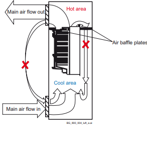
Preventing cooling air recirculation Unit above another
Prevent air recirculation inside and outside the cabinet.
Terminal cover according to VBG 4 regulations
For converter modules size D1 - D4 shrouds for protection against contact are
provided.
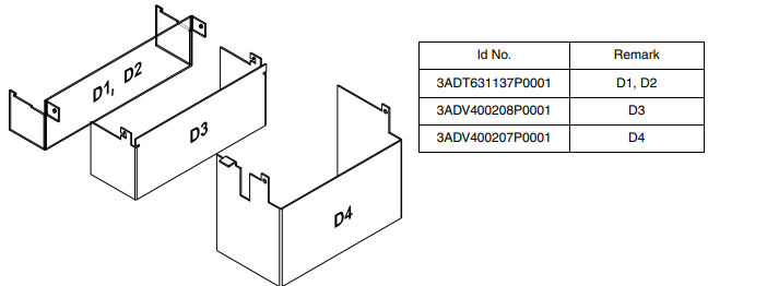
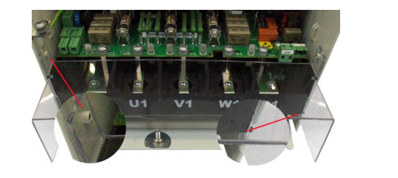
Mount the D1, D2 cover using the existing lateral pins and than swing it down to snap it into the terminal
row. D3 and D4 mounting is the same, without the snap-in mechanism.
Mounting the converter module D4+ inside an enclosure
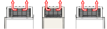
Cooling air inlet
The cooling fan blows the air out of the front, right and left side of the converter
module. View from
View from: right side front side left side:
Free space around the converter module
In mm:
Planning the electrical installation
Chapter overview
This chapter contains the instructions that must be followed when selecting the
motor, cables, protections, cable routing and way of operation for the drive system.
Always follow local regulations. This chapter applies to all DCS800 converter
modules.
Attention:
If the recommendations given by ABB are not followed, the drive may experience
problems that the warranty does not cover. See also Technical Guide.
Options
Line reactors (L1)
For armature and field supply.
When thyristor converters operate, the line voltage is short-circuited during
commutation from one thyristor to the next. This operation causes voltage dips in the
mains PCC (point of common coupling). For the connection of a power converter
system to the mains, one of the following configurations applies:
Configuration A
When using a converter, a minimum of impedance is required to
ensure proper performance of the snubber circuit. Use a line reactor
to meet this minimum impedance requirement. The value must
therefore not drop below 1 % uk (relative impedance voltage). It
should not exceed 10 % uk, due to considerable voltage drops at the
converters outputs.
Configuration B
If special requirements have to be met at the PCC (standards like EN
61 800-3, DC and AC drives at the same line, etc), different criteria
must be applied for selecting a line reactor. These requirements are
often defined as a voltage dip in percent of the nominal supply
voltage. The combined impedance of ZLine and ZL1 constitute the total
series impedance of the installation. The ratio between the line
impedance and the line reactor impedance determines the voltage dip
at the PCC. In such cases, line chokes with an impedance around 4 %
are often used.
Example calculation with ukLine = 1 % and ukL1 = 4 %:
Voltage dip = ZLine / (ZLine + ZL1) = 20 %. Detailed calculations see
-
 Hirschmann RS20-1600M2T1SDAEHH03.1.02 Rail Switch
 -
 Hirschmann BRS30-24TX Industrial Rail Switch
 -
 Hirschmann RSPM20-4T14T1EV9HHS999.9.99 Managed Ethernet Switch
 -
 Hirschmann BELDEN RS40-0009CCCCSDAPHH09.0.14 / RS400009CCCCSDAPHH09014
 -
Hirschmann RS40 Rail Switch RS40-0009CCCCSDAE
-
 Hirschmann BELDEN RS30-0802T1T1SDAP / RS300802T1T1SDAP Fully Managed Layer 2 Compact Rail Switch
 -
 Hirschmann BELDEN RS20-0800M2M2SDAUHH / RS200800M2M2SDAUHH
 -
 Hirschmann EAGLE30-04022O6TT999SCCY9HSE3F Industrial Firewall Router Switch
 -
 Hirschmann RS20-1600T1T1SDAEHH09.0.14 RS20 Rail Mount Ethernet Switch
 -
 Hirschmann EAGLE0200T1T1TDDY90000HHE05.3.03 Industrial Security Router
 -
Hirschmann - BELDEN MIPP-AD-1L9P
-
 HIRSCHMANN RSPM20-4Z64Z6TV9HHS9 942 106-999 RAIL SAFETY SWITCH
 -
 HIRSCHMANN FIBEROPTIC MODULE FIP P/N: OZDFIPG3T
 -
 HIRSCHMANN RS20-1600M2M2SDAUHH Ethernet rack-mounted switch
 -
 HIRSCHMANN BELDEN RS20-0400T1T1SDAEHH04.0.01 / RS200400T1T1SDAEHH04001
 -
HIRSCHMANN MM2-4FXM3 MICE Media Module
-
HIRSCHMANN RS20-0800M2M2SDAE Industrial Ethernet Rail Switch
-
 Hirschmann RS20-2400T1T1SDAP / RS20-2400T1T1SDAPHH05.0.02
 -
 GE MLJ1005B010H00C MLJ Digital Synchromism Check
 -
 ALSTOM MICROTECH DX21-M2 Digital Excitation Controller
 -
HIRSCHMANN BRS20-1200ZZZZ-STCY99HHSES
-
 HIRSCHMANN MM3-4FXM2 MICE Media Module
 -
Hirschmann RSB20-0800T1T1SAABHH 8Port ENet Rail Switch RSB20
-
 Hirschmann MACH102-8TP Ethernet Switch
 -
 SAACKE DDZ-M marine steam pressure atomizer
 -
 SAACKE SKV-A marine rotary cup atomizer
 -
 SAACKE Seavis HMI05e
 -
 Kollmorgen MMC-SD-2.0-230 Servo Drive 100-240VAC 2KW 10A Output 3PH 100-240VAC
 -
 Kollmorgen Servo drive CR10550
 -
 Kollmorgen AKD-P01207-NACN-0054 Servo Driver
 -
 Kollmorgen S406M-CA-036 Servostar
 -
.png) Kollmorgen AKD-B02407-NAAN-0000 Digital Servo Drive
Kollmorgen AKD-B02407-NAAN-0000 Digital Servo Drive -
 Kollmorgen SERVOSTAR S406AM-CA Digital Servo Drive
 -
 KOLLMORGEN SERVOSTAR 603-AS SERVO AMPLIFIER_SERVOSTAR603AS_S60301
 -
Kollmorgen S700 Servo Controller (S70602-NANANA-NA)
-
 Kollmorgen MPK411 controller
 -
 KOLLMORGEN MMC-SD-1.3-460-D Smart Drive
 -
 KOLLMORGEN AKM21C-CKB2AA-00 / AKM21CCKB2AA00 Servomotor
 -
 BECKHOFF AX5106-0000-0200 | Digital Compact Servo Drives 1-channel
 -
 BECKHOFF C3620-0000 INDUSTRIAL COMPUTER (MOTORSHELVES)
 -
 Beckhoff EK1960-0000 TwinSAFE Compact Controller
 -
 Beckhoff C6930-0050 Control Cabinet Industrial PC
 -
 Beckhoff CP7711-0001-0030 Industrial Computer Detection
 -
 Beckhoff CX1001-0111 Embedded PC CPU Module
 -
 Beckhoff C6017-0020 | Ultra-compact Industrial PC
 -
 Beckhoff EK1322 | 2-port EtherCAT P junction with feed-in
 -
 Beckhoff CP2219-0010 Panel
 -
 BECKHOFF C6015-0020 ULTRA COMPACT INDUSTRIAL PC
 -
 BECKHOFF CX2030-0120/Standard CPU Module Embedded PC Windows PLC controller
 -
 Beckhoff CP7721-1090-0020 Panel PC
 -
 Beckhoff PC CPU Module CX5130-0175
 -
 Beckhoff C6920-0050 Control Cabinet
 -
 Beckhoff EL6631 EtherCAT 2-Port Communication Interface, Profinet RT Controller
 -
 Beckhoff CP6202-0001-0060 touch screen panel PC
 -
 Beckhoff CP3916-1002-0000 Multi-Touch Control Panel
 -
 Beckhoff EP1809-0021 | EtherCAT Box, 16-channel digital input, 24 V DC, 3 ms, M8Preferred type
 -
 Beckhoff CX8190 PLC Embedded Industrial PC Ethernet Controller
 -
 Beckhoff CX2100-0914 Power Supply for External
 -
 Beckhoff Automation CP6906-0001-0000 HMI
 -
 Beckhoff EP7342-0002 Module
 -
 Beckhoff CX1020-0112 / CX1100-0910 / CX1020-N010 / CX1100-0003 Windows CPU
 -
 Beckhoff EP7211-0034 EtherCAT Box 1 Channel Motion Interface
 -
 Beckhoff C6240-0030 Control cabinet Industrial PC
 -
 beckhoff motherboard CB1052-0004 CB1052-0004
 -
 Beckhoff AX2006-AS Servo Drive / Variable Frequency Drive
 -
BECKHOFF CP6207-0001-0020 NSMP
-
 Beckhoff C6930-1142-0060 Industrial Computer
 -
 Beckhoff FC7501-0000 interface card
 -
 Beckhoff CX5140-0175 Embedded PC PLC CPU CX5140 Industrial Controller
 -
 Beckhoff CP7802-1100-0010: High-End IP65 Control Panel with DVI/USB Extended Interface
 -
BECKHOFF CP3716-1058-0010 CONTROL PANEL
-
 Beckhoff AX8108-0000 Single-Axis Module
 -
 Beckhoff CU8851-0000 | USB extension, USB Extended 2.0 receiver box
 -
Beckhoff C6017-0030 | Ultra-compact Industrial PC
-
 Beckhoff CX1001-0120/CX10010120.cx1000-n001.cx1000-n000 System Overview
 -
 Beckhoff CPU Module CX5140-0155/4GB CPU Module
 -
 Beckhoff CP6533-0001-005: Built-in Panel PC with High-Definition Multi-Touch Control
 -
 Beckhoff EL5042 | EtherCAT Terminal, 2-channel encoder interface, BiSS® C
 -
 Beckhoff C6920-1080-0040: Premium Control Cabinet Industrial PC
 -
 Beckhoff C6920-0060 | Control cabinet Industrial PC
 -
 Beckhoff Embedded-PC CX5010-1121
 -
 Beckhoff CB3050-0010 Mainboard Motherboard
 -
 Beckhoff PLC module CX1020-0000 Basic CPU module (service phase)
 -
 Beckhoff CP7812-1056-0010 15" Multitouch Display Control Panel
 -
 Beckhoff CX5120-0115 /2GB Controller Module
 -
 Beckhoff CP7201-1000-0000 Industrial Panel PC
 -
 Beckhoff Servo Motor AM8061-0JH1-0000
 -
 BECKHOFF CP6503-0001-0050 Built-in Panel PC
 -
Beckhoff CP3919-0010 Display G190ETN01.2 19" PCT V04. Multi-touch Control Panel
-
 Beckhoff CX5110-0112-9020/000368201 Embedded PC Intel Atom Processor
 -
 Beckhoff AX8206-0000 Dual-Axis Module
 -
Beckhoff Nail Operating Terminal CP7032-1031-0010
-
Beckhoff AM8042-0EH1-0000 Servomotor 4.10 Nm (M0), F4 (87 mm)
-
 Beckhoff EK9300 Beckhoff CPU Module
 -
Beckhoff CP3224-0020 Multitouch-Panel-PC
-
 Beckhoff CP2712-0000 12.1" 24VDC Touch Screen WMD0
 -
 BECKHOFF CX5240-0195 / 0000289234 Embedded PC 40 GB CFast Card
 -
 Beckhoff CP6932-1000-0000 Control Panel
 -
 BECKHOFF CX5120-0121 PLC Module
 -
 Beckhoff EL3218 | EtherCAT Terminal, 8-channel analog input
 -
Beckhoff C6640-0050 | Control cabinet Industrial PC
-
 Beckhoff Cx5130-0120/4GB Embedded-PC
 -
 BECKHOFF CX2030-0122 PLC PROCESSOR
 -
 BECKHOFF CX5020-0122 Controller Module
 -
 Beckhoff CP3915-0000 Multitouch Panel
 -
 BECKHOFF EL3014 | EtherCAT Terminal
 -
 BECKHOFF Industrial Computer c6920-1057-0030
 -
 Beckhoff CX5130-0141/4GB CX5130-0141 Embedded PC
 -
 Beckhoff C6240-1052-0040 4-086-06-3073 Industrial Computer
 -
 Beckhoff CX5140-0135 /4GB High-Performance Embedded Industrial PC
 -
 Beckhoff C6515-1001-0000 Industrial PC
 -
 Beckhoff AX5103-0000-0200 - Digital Compact Servo Drives
 -
 Beckhoff CX2030-0130-1003/4GB Basic CPU module
 -
 Beckhoff AX8620-0000 Power Supply Module
 -
 Beckhoff CX9020-0111 module with
 -
 Beckhoff EL7332 PLC Module
 -
 BECKHOFF CP7709-0001-0020 HMI
 -
 Beckhoff CX5120-0155/2GB Embedded PC
 -
 BECKHOFF CP7037-1037-0010 OPERATOR INTERFACE TOUCHSCREEN
 -
 Beckhoff EK9000 | ModbusTCP/UDP Bus Coupler
 -
 Beckhoff Touch Panel Screen CP6020 -0000-0000
 -
 Beckhoff CX2020-0121 Module FAST Shipping
 -
 Beckhoff CX2030-0125 Basic CPU Module
 -
 Beckhoff CP3918-0000 Multi-Touch 18.5" Control Panel
 -
 Automotion LC4A00010 DC BL Motor Control, ATS, Sub Assy, SCP, 115VAC,
 -
 500T-115VAC - VAS ENGINEERING - DORIC 500 SERIES DIGITAL TEMP INDICATOR
 -
 Honeywell X-DCS2000/EN Digital Integrated System Manager 50/60Hz 100-240V #4
 -
 Kollmorgen S60600 Servostar600 606-Fan 4 kVA, 6 A, 3 X 230 - 480 V


