
ABBProduct specification
Overview of this specification About this product specification It describes the performance of the manipulator oracomplete family of manipulators in terms of:
• The structure and dimensional prints
• The fulfilment of standards, safety and operating requirements
• The load diagrams, mounting of extra equipment, the motion and the robot reach
• The specification of variants and options available
Usage Product specifications are used to find data and performance about the product, for example to decide which product to buy. How to handle the product is described in the product manual.
Users It is intended for:
• Product managers and product personnel
• Sales and marketing personnel
• Order and customer service personnel
1 Description
1.1 Structure
1.1.1 Introduction to structure
General
The IRB 1200 is one of ABB Robotics latest generation of 6-axis industrial robot, with a payload of 5 to 7 kg, designed specifically for manufacturing industries that use flexible robot-based automation, e.g. 3C industry. The robot has an open structure that is especially adapted for flexible use, and can communicate extensively with external systems
Type A of IRB
1200 Type A - Axis Calibration
The difference between IRB 1200 and IRB 1200 Type A is that the Type A is calibrated with Axis Calibration. On each axis there are bushings for installation of calibration tools. As a result of this, the castings differ between IRB 1200 and IRB 1200 Type A
Note IRB 1200 Type B is designed based on IRB 1200 Type A so that Type B has the bushings for installation of calibration tools too. The difference between IRB 1200 Type A and IRB 1200 Type B is that Type B also supports SafeMove 2. See Type B of IRB 1200 on page 9. How to know which type the robot is? The type label on the base of the robot tells if the robot is calibrated with Axis Calibration. Those robots are named IRB 1200 Type A.
1.1.1 Introduction to structure Continued
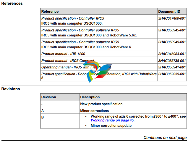
Particle emission from the robot fulfill Clean room class 3 standard according to DIN EN ISO 14644-1. Clean room robots are specially designed to work in a clean room environment. According to IPA test result, the robot IRB 1200 is suitable for use in clean room environments. Clean room robots are designed in order to prevent from particle emission from the robot. For example is, frequent maintenance work possible to perform without cracking the paint. The robot is painted with four layers of polyurethane paint. The last layer being a varnish over labels in order to simplify cleaning. The paint has been tested regarding outgassing of Volatile Organic Compounds (VOC) and been classified in accordance with ISO 14644-8. Classification of airborne molecular contamination, see below:
Food grade lubrication The robot has food grade lubrication (NSF H1) as an option (777-1). The protection type for robots with food grade lubrication is Clean Room and IP67.
IP67/66 protection The robot has IP67 as an option. The option will add sealing, machining parts and gasket.
Protection type Foundry Plus 2 Robots with the option Foundry Plus 2 are designed for harsh environments where the robot is exposed to sprays of coolants, lubricants and metal spits that are typical for die casting applications or other similar applications. Typical applications are spraying insertion and part extraction of die-casting machines, handling in sand casting and gravity casting, etc. (Please refer to Foundry Prime robots for washing applications or other similar applications). Special care must be taken in regard to operational and maintenance requirements for applications in foundry are as well as in other applications areas. Please contact ABB Robotics Sales organization if in doubt regarding specificapplication feasibility for the Foundry Plus 2 protected robot. The robot is painted with two-component epoxy on top of a primer for corrosion protection. To further improve the corrosion protection additional rust preventive are applied to exposed and crucial areas, e.g. has the tool flange a special preventive coating. Although, continuous splashing of water or other similar rust formation fluids may cause rust attach on the robots unpainted areas, joints, or other unprotected surfaces. Under these circumstances it is recommended to add rust inhibitor to the fluid or take other measures to prevent potential rust formation on the mentioned. The entire robot is IP67 compliant according to IEC 60529 - from base to wrist, which means that the electrical compartments are sealed against water and solid contaminants. Among other things all sensitive parts are better protected than the standard offer. Selected Foundry Plus 2 features: • Improved sealing to prevent penetration into cavities to secure IP67 • Additional protection of cabling and electronics • Special covers that protect cavities • Well-proven connectors • Black chrome coated tool flange • Rust preventives on screws, washers and unpainted/machined surfaces • Extended service and maintenance program The Foundry Plus 2 robot can be cleaned with appropriate washing equipment according to the robot product manual. Appropriate cleaning and maintenance is required to maintain the protection, for example can rust preventive be washed off with wrong cleaning method. Available robot versions The option Foundry Plus 2 might not be available for all robot versions. See Specification of variants and options on page 53 for robot versions and other options not selectable together with Foundry Plus 2.
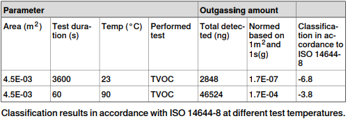
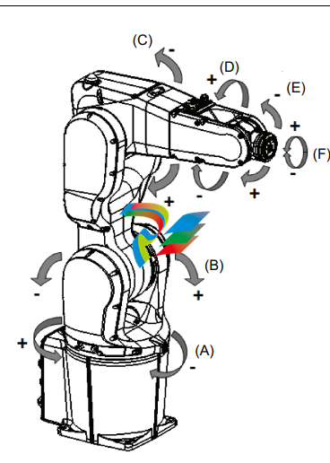
perating system The robot is equipped with the IRC5 Compact (IRC5C) or IRC5 (Single cabinet) controller and robot control software, RobotWare. RobotWare supports every aspect of the robot system, such as motion control, development and execution of application programs, communication etc. See Product specification - Controller IRC5 with FlexPendant (IRC5C included). Safety The safety standards are valid for the complete robot, manipulator and controller. Additional functionality For additional functionality, the robot can be equipped with optional software for application support - for example gluing and welding, communication features - network communication - and advanced functions such as multitasking, sensor control etc. For a complete description on optional software, see Product specification - Controller software IRC5. Manipulator axes (A) (D) (E) (F) (C) (B) xx1300000365 Continues on next page 12 Product specification - IRB 1200 3HAC046982-001 Revision: K © Copyright 2019 ABB. All rights reserved. 1 Description 1
1.3 Installation 1.3.1 Introduction to installation General IRB 1200 is adapted for normal industrial environment. Depending on robot variant, an end effector with max. weight of 5 or 7 kg, including payload, can be mounted on the robot’s mounting flange (axis 6). Other equipment, weighing a maximum of 0.3 kg, can be mounted on the upper arm. For more information about mounting of extra equipment, see Fitting of equipment on page 32
1.4.1 Introduction to load diagram1.4 Load diagram 1.4.1 Introduction to load diagram Information WARNING It is very important to always define correct actual load data and correct payload of the robot. Incorrect definitions of load data can result in overloading of the robot. If incorrect load data and/or loads are outside load diagram is used the following parts can be damaged due to overload: • motors • gearboxes • mechanical structure WARNING In the robot system is the service routine LoadIdentify available, which allows the user to make an automatic definition of the tool and load, to determine correct load parameters. For detailed information, see Operating manual - IRC5 with FlexPendant. WARNING Robots running with incorrect load data and/or with loads outside diagram, will not be covered by robot warranty. General The load diagram includes a nominal pay load inertia, J0 of 0.06 kgm2 and an extra load of 0.3 kg at the upper arm housing. At different moment of inertia the load diagram will be changed. For robots thatare allowed tilted, wall or inverted mounted, the load diagrams as given are valid and thus it is also possible to use RobotLoad within those tilt and axis limits. Control of load case by "RobotLoad" To easily controla specific load case, use the calculation program ABB RobotLoad. Contact your local ABB organization for more information. The result from RobotLoad is only valid within the maximum loads and tilt angles. There is no warning if the maximum permitted armload is exceeded. For over load cases and special applications, contact ABB for further analysis.
1.6.3 Absolute Accuracy calibration Continued
When is Absolute Accuracy being used Absolute Accuracy works on a robot target in Cartesian coordinates, not on the individual joints. Therefore, joint based movements (e.g. MoveAbsJ) will not be affected. If the robot is inverted, the Absolute Accuracy calibration must be performed when the robot is inverted. Absolute Accuracy active Absolute Accuracy will be active in the following cases:
• Any motion function based on robtargets (e.g. MoveL) and ModPos on robtargets • Reorientation jogging • Linear jogging
• Tool definition (4, 5, 6 point tool definition, room fixed TCP, stationary tool)
• Work object definition Absolute Accuracy not active The following are examples of when Absolute Accuracy is not active:
• Any motion function based on a jointtarget (MoveAbsJ)
• Independent joint
• Joint based jogging
• Additional axes
• Track motion Note In a robot system with, for example, an additional axis or track motion, the Absolute Accuracy is active for the manipulator but not for the additional axis or track motion. RAPID instructions There are no RAPID instructions included in this option. MultiMove If the main robot in a MultiMove system has the Absolute Accuracy option, it opens up Absolute Accuracy capability for all the robots in the system. However, each robot needs to be calibrated individually. Note Note that this is the only RobotWare option that is relevant for an additional robot.
1.7 Maintenance and troubleshooting 1.7.1 Introduction to maintenance and trouble shooting General The robot requires only a minimum of maintenance during operation. It has been designed to make it as easy to service as possible:
• Maintenance-free AC motors are used.
• Grease used for all gearboxes.
• The cabling is routed for longevity, and in the unlikely event of a failure, its modular design makes it easy to change. Maintenance The maintenance intervals depend on the use of the robot, the required maintenance activitiesalso depends on selected options. For detailed information on maintenance procedures, see Maintenance section in the Product Manual - IRB 1200.
Customer connections Introduction to customer connections The cables for customer connection are integrated in the robot and the connectors are placed on the tubular housing (upper arm) and one at the base. There is one connector R4.CP/CS at the tubular housing. Corresponding connector R1.CP/CS is located at the base. It is recommended to use a fuse protector for customer connection; otherwise, application overload will burn out the CP/CS cables in the robot. Detailed information about the CP/CS connection is provided in a warning label on the tubular housing.
There is also connections for Ethernet, one connector R4.Ethernet at the tubular housing and the corresponding connector R1.Ethernet located at the base.
-
 OMRON 3G3XV-A2007 3G3XV-A2007-NEV2
 -
 Omron NJ1019000 NJ1 programable logic controller
 -
 OMRON C120-LK202-EV1/C120LK202EV1
 -
 OMRON C200H-AD003 PLC
 -
 OMRON C200H-CPU23-E COIL 24VDC PLC
 -
 Omron C200HG - C200H-ID212- C200H-OC226 C200HW-BC101 PLC Base Unit
 -
 OMRON C200H-OC222(Output Unit),C200H-PS211(Power Supply Unit),SP001 Module Rack
 -
 OMRON C200H-RT201 PROGRAMMABLE CONTROLLER
 -
 OMRON C200HS-CPU01-E SYSMAC PROGRAMMABLE CONTROLLER
 -
 OMRON C200H-SNT31 C200H Programmable Controllers
 -
 OMRON C200HW-MC402-E Motion control unit
 -
 OMRON C200PC-ISA02-DRM-E PLC ISA bus compatible board card
 -
 OMRON C500-CT012 PLC
 -
 OMRON C500-NC103-E PLC
 -
 OMRON C500-NC222-E PLC
 -
 OMRON C500-PRW05-V1 PLC
 -
 OMRON C500-PRW06 PROGRAMMABLE CONTROLLER
 -
 OMRON C500-PS223-E 3G2A5-PS223-E PLC SYSMAC PROGRAMMABLE CONTROLLER
 -
 OMRON C500-TU001 3G2A5-TU001 PLC PLC
 -
 OMRON C60H-C1DR-DE-V1 Programmable Controllers
 -
 OMRON C60H-C5DR-DE-V1 Programmable Controllers
 -
 OMRON C60H-C6DR-DE-V1 Programmable Controllers
 -
 OMRON CJ1G-CPU44H CPU module
 -
 OMRON CJ1G-CPU45H PLC
 -
 OMRON CJ1M-CPU13-ETN V4.0 PLC PLC
 -
 OMRON CJ1W-AD041-V1 Analog input uni
 -
 OMRON CJ1W-CORT21 PLC module
 -
 OMRON CJ1W-IDP01 Input unit
 -
 OMRON CJ1W-MCH71 - MECHATROLINK-II
 -
 OMRON CJ1W-MD261 Digital I/O
 -
 OMRON CJ1W-NC413 Position control unit
 -
 OMRON CJ1W-NCF71 Position Control Units
 -
 OMRON CJ1W-PTS51 Process Simulation I/O Module
 -
 OMRON CJ1W-PTS52 Process Simulation I/O Module
 -
 OMRON CJ1W-SCU21-V1 PLC
 -
 Omron CJ1W-SCU22 Serial Communication Unit
 -
 OMRON CJ1W-TC001 CJ Series Temperature Control Unit
 -
 Omron CK3W-AX1515N Motion Controller
 -
 Omron CP1E-N60DR-D Compact PLC CPU
 -
 OMRON CP1E-NA20DT1-D PLC PLC
 -
 OMRON CP1H-X40DT-D plc PLC
 -
 OMRON CPM2C-S110C-DRT Interface module
 -
 OMRON CQM1-AD041 PLC
 -
 SAACKE F‑GDSA‑1 / F‑GDSA‑2 Feuerungsautomaten
 -
 SAACKE F-GDSA 143303 Controller SHIPS UPS
 -
 ICS Triplex T8270 Trusted 24 Vdc FanAssembly
 -
 SCHNEIDER M522220000 SA SM_DO16R 16 DIGITAL OUTPUTS MODULE
 -
 LENZ EPL10200-W EPZ-10203 CANPT010W3E
 -
 OMRON CQM1H-ADB21 PLC
 -
OMRON CQM1H-CPU61 PLC
-
 OMRON CQM1H-MAB42 PLC
 -
 OMRON CQM1-TC102 CQM1-TC101 PLC
 -
 OMRON CS1G-CPU44-EV1 PLC
 -
 OMRON CS1G-CPU44H CPU
 -
OMRON CS1H-CPU63-EV1 PLC
-
 OMRON CS1H-CPU66-V1 PLC
 -
 OMRON CS1W-CLK13 PLC communication module
 -
OMRON CS1W-EIP21 PLC
-
 OMRON CS1W-MAD44 PLC PLC
 -
 OMRON CS1W-SCU31-V1 CVM1-BC103 PLC
 -
 Omron CVM1-CPU21-V2 CPU Unit
 -
 OMRON F150-C10E-2 Vision Controller
 -
 OMRON F150-C15E-3 Vision Controller
 -
 OMRON F160-C15E VISION MATE CONTROLLER
 -
 OMRON F500-C10-ETN F500-C15-ETN Vision Sensor
 -
 OMRON F500-VS F500-S1
 -
 OMRON FH-3050 FH Vision Controller
 -
 Omron FQ2-S25050F PLC Smart Camera
 -
 Omron FQM1-MMA22 Motion Module
 -
 OMRON GRT1-TS2P Temperature Module
 -
 OMRON H8PR-24 Cam Positioner
 -
 OMRON IDSC-C1DR-A-E Controller
 -
 OMRON K3HB-HTA-DRT1 Temperature Panel Meter
 -
 Omron KM-N1-FLK Power Detector
 -
 OMRON CJ1G-CPU43H CPU
 -
 OMRON NA5-7W001S-V1 NA5-9W001B-V1 NA5-12W101B-V1 Graphic panel
 -
 OMRON NA5-9W001B-V1 Graphic panel
 -
 OMRON NB10W-TW01B INTERACTIVE DISPLAY
 -
 OMRON NB7W-TW01B +CP1L-EL20DR-D Complete Power Panel
 -
 OMRON NB7W-TX01B INTERACTIVE DISPLAY PLC
 -
 Omron NE1A-SCPU02 Network Controller
 -
 OMRON NA5-7W001B-V1 NA5-7W001S-V1 NA5-9W001B-V1 NA5-12W101B-V1 touch screen
 -
 Omron NS5-SQ00B-V2 NS5-SQ00-V2 NS5-SQ01-V2 NS5-SQ01B-V2 touch display panel
 -
 Omron NJ301-1100 Programmable Logic Controller
 -
 OMRON NJ501-1300 CUP Unit Programmable Controller
 -
 Omron NS12-TS01B-V2 Interactive Display
 -
 OMRON NSJW-ETN21 ETHERNET HMI
 -
 OMRON NT10S-SF121 PLC
 -
 OMRON NT20S-ST121-EV3 Touch Screen
 -
 Omron NX1P2-1140DT-BA Programmable Controller
 -
 OMRON 3G3MV-P10CDT3-E RS422/485 INVERTER BOARD
 -
 Omron C500-ID219 3G2A5-ID219 System Microprocessor
 -
 Omron PLC B7AM-8B16
 -
 OMRON PLC Module CJ1W-AD081-V1
 -
 OMRON R88D-HS10 PLC
 -
OMRON R88D-HT10 plc
-
 OMRON R88D-KN01H-ML2 Servos G5-series
 -
 OMRON R88M-H10030-B plc
 -
 OMRON R88S-H306G plc PLC
 -
 Omron Relay G9SX-GS226-T15-RT
 -
 Omron S8AS-24006N S8AS Smart Power Supply FNIP
 -
 Omron Safety Input Unit NX-SIH400
 -
 OMRON SYSMAC SCY-P1 Sequential Controller
 -
OMRON SYSMAC SCY-P0 13E Sequential Controller
-
 OMRON NS8-TV00B-V2 NS8-TV00-V2 NS8-TV00B-ECV2 NS8-TV00-ECV2 touch display Panel
 -
 Omron V680-CA5D02-V2 Programmable Controller
 -
 OMRON SGDH-04AE-OY Servo Drive
 -
OMRON SGDH-10DE-OY Servo Drive
-
 OMRON SGDS-02A12A PLC + SGMAS-C2ACA21
 -
 OMRON SGMPH-04AAA61D-OY Servo Motor
 -
 Omron ZFV-CA40 Smart Sensor Amp Unit 24VDC 0.8A
 -
OMRON ZFV-NX1 CFP0260 ZFV-A20 VISION CONTROL PANEL
-
 OMRON ZFX-C15 SMART SENSOR AMP UNIT, Vision Sensor LCD
 -
 OMRON ZFX-C20/25-CD SMART SENSOR AMP UNIT, Vision Sensor LCD
 -
 OMRON-DIGITAL TEMPERATURE CONTROLLER E5AC-CX4A5M-014 r
 -
 ABB PFVL141V-2.0MN is an industrial-grade, rectangular roll force load cell
 -
 ABB PFVL141V-1.6MN is an industrial-grade, rectangular roll force load cell
 -
ABB PFVL141V-1.25MN high-performance, rectangular roll force load cell
-
 ABB PFVL141V-1.0MN high-precision, heavy-duty rectangular load cell
 -
 ABB PFVL141V-0.8MN high-precision, heavy-duty rectangular load cell
 -
 ABB PFVL141V-0.63MN high-precision, heavy-duty rectangular load cell
 -
 GE 151X1202YE08PP08 Panel of the case / Structural component
 -
 GE 151X1212HB01MG02 Integrated LCI Controller (Old Model)
 -
 GE 151X1212GC01PC02 LCI Static Startup Controller
 -
 GE 151X1235FD01PK01 High-speed Digital Input Interface Board
 -
 GE 151X1215DK01PC01 Signal Processing / Amplification Board
 -
 GE 151X1238WP99BK01 6-pulse LCI power conversion module
 -
 GE 151X1225DF01PC03RA - Power Conversion / Drive Regulation Board


