
ABBDCS800 Quick guide DCS800 Drives (20 A to 5200 A)
ABB Drive Service EN
In order to offer the same after sales
service to our customer around the
world, ABB has created the DRIVE
SERVICE CONCEPT.
ABB's after sales service is globally
consistent due to common targets,
rules, and the way of operation. This
means for our customers:
Please visit the ABB drive service
homepage
www.abb.com/drivesservices
ABB Drive Service FR
Pour offrir la même qualité de service
à tous nos clients, ABB a créé DRIVE
SERVICE CONCEPT.
Dans le monde entier, les équipes
de service proposent les mêmes
prestations aux mêmes conditions
avec les mêmes objectifs.
Pour en savoir plus, connectez-vous sur ABB drive service
homepage
www.abb.com/drivesservices
ABB Drive Service DE
Um jedem Kunden rund um die
Welt die gleiche Service Dienstleistung anbieten zu können, hat ABB
das DRIVE SERVICE CONCEPT
entwickelt.
Durch die Definition von einheitlichen
Zielen, Regeln, und Arbeitsvorschriften kann ABB die Dienstleitungs
Produkte weltweit auf gleichwertig
hohem Qualitätsniveau anbieten. Für
unsere Kunden bedeuted dies:
Bitte besuchen Sie die ABBHomepage Service für Antriebe
www.abb.com/drivesservices
ABB Drive Service IT
ABB ha creato il DRIVE SERVICE
CENCEPT, con lo scopo di offrire ai
nostri clienti lo stesso servizio post
vendita in tutto il mondo.
Attraverso la definizione di obbiettivi
comuni, ruoli e modo di operare, le
attività post vendita di ABB offrono
sevizi coerenti nella loro globalità. Per
i nostri clienti questo significa:
Vi invitiamo a visitare la homepage
ABB drive service
www.abb.com/drivesservices
ABB Drive Service ES
Para poder ofrecer el mismo servicio posventa a nuestros clientes
en todo el mundo, ABB ha creado
el CONCEPTO DE SERVICIO DE
CONVERTIDORES.
El servicio posventa de ABB está
mundialmente consolidado gracias
a unos objetivos y normas comunes,
así como a su funcionamiento. Esto
significa para nuestros clientes:
Visiten el portal de convertidores
de ABB
Brief instructions for CD and documents overview
We appreciate that you purchased an ABB DC drive
power converter and thank you for the trust you put in our
products.
This brochure was put together to make sure that you continue
to be satisfied with our product. It is intended to provide you
with a brief overview of the product's key data, EMC notes,
typical applications, start-up and trouble-shooting.
If you need more information about the product you are
provided with a CD-ROM in addition to this brief documentation. The CD-ROM is part of this document and features
the following contents:
Documentation
Our documentation is basically structured according to the
following system:
Technical catalogue (3ADW000192)
as comprehensive information to engineer complete DC
drive systems.
Hardware manual (3ADW000194)
as detailed information, with all important particulars about
the individual components, like module dimensions, electronic
boards, fans and auxiliary components.
Information for mechanical and electrical installation are
also included.
Firmware Manual (3ADW000193)
detailed information with all important issues about firmware
and setting of parameters. The manual includes information
for start-up and maintenance of the entire drive, in detailed
form.
This manual also includes Fault and Alarm codes and information for trouble shooting.
Service Manual (3ADW000195)
for maintenance and repair of the converters.
Applications
DCS800 DC Drive can include application software e.g.
cranes, winders. In such case following procedures and
assistants can be blocked or not completed. Please check
for further documentation and manuals (check parameter
4.03, 83.01).
Additional information about applications (e.g. 12-pulse)
and technical accessories (e.g. Hardware extension or
Field bus interfaces) are handled by separate manuals. See
table DCS800 Drive manuals.
System requirements to use the CD-ROM
• Operating system WINDOWS 2000, XP
• ACROBAT READER 4.0 is
sufficient (we recommend
8.0 - included on the CDROM)
In case the CD ROM does not start automatically please
double-click on Setup.exe.
Further support
In addition we offer further support, since we can only be
satisfied when you, as our customer, are satisfied with us
and our products.
Internet
On the ABB homepage under
www.abb.com/dc
you'll find abundant information for
• DC products
• service support
• the latest updates
• tools
• downloads, etc.
Please don't hesitate to visit us.
Contacts
If you require any further information, please contact your
nearest ABB Drives office or send an email to:
DC-Drives@de.abb.com
Please give us your name, your company address and
phone number. We immediately put you in contact with our
specialist.
Notes on EMC
You will find further information in publication:
Technical Guide chapter:
EMC Compliant Installation and Configuration for
a Power Drive System
The paragraphs below describe selection of
the electrical components in conformity with
the EMC Guideline.
The aim of the EMC Guideline is, as the name
implies, to achieve electromagnetic compatibility with other products and systems. The
guideline ensures that the emissions from
the product concerned are so low that they
do not impair another product‘s interference
immunity.
In the context of the EMC Guideline, two
aspects must be borne in mind:
• the product‘s interference immunity
• the product‘s actual emissions
The EMC Guideline expects EMC to be taken
into account when a product is being developed;
however, EMC cannot be designed in, it can only
be quantitatively measured.
Note on EMC conformity
The conformity procedure is the responsibility of
both the power converter‘s supplier and the manufacturer of the machine or system concerned, in
proportion to their share in expanding the electrical
equipment involved.
For compliance with the protection objectives
of the German EMC Act (EMVG) in systems and
machines, the following EMC standards must
be satisfied:
Product Standard EN 61800-3
EMC standard for drive systems (PowerDriveSystem), interference immunity and emissions
in residential areas, enterprise zones with light
industry and in industrial facilities.
This standard must be complied with in the EU
for satisfying the EMC requirements for systems
and machines!
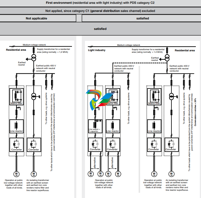
Classification
The following overview utilises the
terminology and indicates the action required in accordance with
Product Standard
EN 61800-3
For the DCS800 series, the limit
values for emitted interference
are complied with, provided the
measure indicated is carried
out. PDS of category C2 (formerly restricted distribution in
first environment) is intended to
be installed and commissioned
only by a professional (person
or organization with necessary
skills in installing and/or commissioning PDS including their
EMC aspects).
For power converters without
additional components, the following warning applies:
This is a product of category C2
under IEC 61800-3:2004. In a
domestic/residential environment
this product may cause radio
interference in which case supplementary mitigation measures
my be required.
The field supply is not depicted
in this overview diagram. For the
field current cables, the same
rules apply as for the armaturecircuit cables.
M M M M
emv_clssif_b.dsf
Converter
transformer
Case-referenced EMC analysis
alternative
Converter
transformer
with earthed
iron core
(and earthed
screen where
appropriate)
alternative
I > 400 A
and/or
U > 500 V
Operation with separate power converter transformer. If there
are other loads at the same secondary winding, these must be
able to cope with the commutation gaps caused by the power
converter. In some cases, commutating reactors will be
required.
To other loads, e.g. drive systems
Converter Converter
Line reactor
Medium-voltage network
Industrial
zone
For emitted interference, the following apply:
EN 61000-6-3 Specialised basic standard for emissions in light industry
can be satisfied with special features (mains filters, screened
power cables) in the lower rating range *(EN 50081-1).
EN 61000-6-4 Specialised basic standard for emissions in industry
*(EN 50081-2)
For interference immunity, the following apply:
EN 61000-6-1 Specialised basic standard for interference immunity in
residential areas *(EN 50082-1)
EN 61000-6-2 Specialised basic standard for interference immunity in industry. If this standard is satisfied, then the EN 61000-6-1
standard is automatically satisfied as well *(EN 50082-2).
* The generic standards are given in brackets
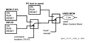
START, STOP and E-STOP control
The relay logic can be split into three parts:
a: Generation of the ON/OFF and START/STOP command:
The commands represented by K20 and K21 (latching interface relay) can be e.g. generated by a PLC and transferred to
the terminals of the converter either by relays, using galvanic
isolation or directly via 24V signals.
These commands can be as well transferred via serial
communication. Even a mixed solution can be realized by
selecting different possibilities for the one or the other signal
(see parameter group 11).
b: Generation of control and monitoring signals:
The main contactor K1 for the armature circuit is controlled
by a dry contact (DO 8) located on the SDCS-PIN-4. Status
of fans and fans klixon can be monitored by means of fan
ack signals: MotFanAck (10.06) and ConvFanAck (10.20).
c: OFF2, OFF3 Stop function:
Beside ON/OFF and START/STOP, the drive is equipped
with two additional stop functions, OFF2 and OFF3, according to Profibus standard. OFF3 is a scalable stop function
(rampstop, max torque stop, dynamic braking …) to perform
stop category 1. This function should be connected to the
E-STOP button without any time delay. In case of ramp stop
selection the, K 15 timer relay must be set longer than the
EStopRamp (22.04). For COAST selection, the drive opens
the main contactor immediately.
OFF2 switches off DC current as fast as possible and prepares the drive for opening main contactor or drop down
mains supply. For a normal DC motor load the time to switch
OFF the DC current is below 20 ms. This function should be
connected to all signals and safety functions opening the main
contactor. This function is important for 4-quadrant drives.
Do not open main contactor during regenerative current.
The correct sequence is
1. switch off regenerative current
2. then open the main contactor
In case of the E-STOP is hit, the information is transferred
to the converter via digital input 5. In case of rampstop, or
max torque selection the converter will decelerate the motor
and then open main contactor.
If the drive has not finished the function within the K15 timer
setting, the drive must get the command to switch OFF the
current via K16. After K16 timer set has elapsed the main
contactor is opened independent of the drives status.

Notes For North American Installations
1. EMC conformity is not usually required in North America. In most cases, the section “Notes on EMC” can be
bypassed. In this manual, you will see references to DIN, EN
and VDE standards. These are European standards and,
generally, do not apply to North America. It is, however,
the responsibility of the user to determine which standards
need to be followed.
2. If using a DC contactor, you must connect an auxiliary
contact to a digital input of your choice and set para. MainContAck accordingly. Set the following parameters:
MainContAck (10.21) = DI-1 (or any input you
choose for the DC cont.
auxiliary contact)
DO8BitNo (14.16) = 10
MainContCtrlMode (21.16) = DCcontact (3)
Set these parameters AFTER macros are loaded but BEFORE
the drive is commissioned.
Digital output 8 (DO-8) must be used to turn the DC
contactor on and off.
3. If using Dynamic Braking, the drive allows you to select the stopping method under three different situations.
Parameters 21.02, 21.03 and 21.04 select the stopping
method for loss of
the OnOff, run command (StartStop, Jog1, Jog2, etc.), and
E-Stop input, respectively.
Each can be set to:
• RampStop • TorqueLimit
• CoastStop • DynBraking
In order to command the drive to perform a DB stop, one
or more of these parameters must be set to DynBraking.
Most users will want the drive to ramp stop when OnOff or a
run command (StartStop, Jog1, Jog2, etc.) input is cleared,
and dynamically brake when the E-Stop input is cleared. In
that case, use the following settings:
• Off1Mode (21.02) = RampStop
• StopMode (21.03) = RampStop
• E StopMode (21.04) = DynBraking
However, any case is allowed and the final decision is left
to the user.
Other parameters control stops during faults.
See:
LocalLossCtrl (30.27) ComLossCtrl (30.28)
FaultStopMode (30.30) SpeedFbFltMode (30.36)
If using EMF feedback with dynamic braking, set:
• DynBrakeDly (50.11) = t
Where: t = the time (sec) it normally takes the motor
to stop during dynamic braking
DC contactor US:
DC contactor US K1.1 is a special designed contactor with 2x
NO contacts for C1 and D1 connection and 1x NC contact for
connection of Dynamic Brake resistor RB.
The contactor should be controlled by signal 6.03 Bit 10.
The acknowledge can be connected to parameter:
10.21 MainContAck
10.23 DCBreakAck
Overview of the Installation and Commissioning Process
This is to protect the motor and converter if a commutation
fault should occur. NOTE: DC output fuses are the same
type and size as AC line fuses.
Line reactor:
All thyristor-based dc converters cause notching in the AC
line due to motor commutation. A properly sized line reactor
will mitigate the effect on the line. Unless the converter uses
a dedicated isolation transformer, each converter requires
its own line reactor.
AC or DC contactor:
A contactor is required to safely disconnect the motor from
the incoming power when the converter is off. The contactor
can be installed between the line and the converter (an AC
contactor) or between the converter and the motor (a DC
contactor). Do not use both.
IMPORTANT: Other equipment may be necessary depending on application and local codes.
Step 1:
Check converter for damage. Contact ABB Technical Support
if damage is found. In North America, call 1-800-435-7365
(1-800-HELP-365)
Step 2:
Select supporting hardware for the converter:
For specific recommendations for fuses, reactors, and
contactors, see the DCS800 hardware manual or technical
catalog.
Circuit breaker or disconnect:
Current rating = Idc * 0.816 * 1.25 (min)
= Idc * 0.816 * 2.50 (max)
Where: Idc = nominal DC motor current
Fuses:
AC Line Fuses: To properly protect the converter, semiconductor fuses on the incoming AC power line are required
in all cases.
DC Output Fuses: Fuses between the motor and the
converter are required for all regenerative (4-Q) converters.
Step 3:
Mount and wire the converter and supporting hardware inside an industrial enclosure with adequate cooling (DCS800
modules have rating of NEMA type OPEN).
The following control and signal wiring is required:
o If using an AC contactor, we recommend wiring an auxiliary contact to the digital input you have designated as
MainContAck (10.21) or Start/Stop (10.16).
o If using a DC contactor, you must wire an auxiliary contact
from the contactor to the digital input you have designated
as MainContAck (10.21).
o Wire 115 or 230 Vac 1-phase power to terminal block 99
for converter control power.
o Wire 1-phase power to converter for cooling fans. See
table and wiring diagrams in this manual.
• D1 – D3 frames: 115/230 Vac selectable. Fan
terminal X2 is on top of the converter.
• D4 frame: If type code includes +S171, use 115
Vac; otherwise use 230 Vac. Fan terminal X2 is
on top of the converter.
o Wire tachometer or encoder to terminal block X3 (tacho)
or X5 (encoder).
o Wire analog inputs (e.g., speed reference) and outputs
(e.g., meters for motor voltage, current) to terminal block
X3 and/or X4.
o Wire high speed serial interface if needed. (Requires
optional fieldbus interface board.)
o The DCS800 allows you to choose the usage of each
digital and analog input and output. The converter has
factory default settings which can be changed by loading
a macro, but some designations are universal. They
include:
• Digital input 5: Estop
• Digital input 6: Fault reset
• Digital input 7: On/Off (maintained) or On-Start
(pulsed)
• *Digital input 8: Start/Stop (maintained) or OffStop (pulsed)
• Digital output 8: Main Contactor On (3 Amps
max. at 115 – 230 Vac)
*except Hand/Auto macro
o Other signals may be required depending on your application (e.g., motor fan acknowledge input, Off2 input,
fan-on output, brake output).
o You will select the macro and / or choose the configuration
for digital and analog inputs and outputs in step 2 of the
commissioning process, or by updating group 10 and 14
parameters.
o Check all wire terminations (with continuity tester) before
proceeding to the next step.
Step 4:
Connect the drive system to incoming power and the motor to
the converter (both field and armature) as well as accessory
equipment (motor fan, thermal switch, brake, etc.).
o See hardware manual for typical cable size and tightening
torque recommendations.
o IMPORTANT: Be sure all safety equipmentis properly
sized for your application
Step 5:
Apply control power to the converter.
o IMPORTANT: See section “Safety and Operating
Instructions” in this manual before proceeding.
o Apply power to terminal block 99 and X2. The keypad
should light up and show the menu screen. The converter
fans should start to run (if converter has fans).
Step 6:
Commission the converter using Drive Windows Light
(preferred) or the control panel.
o IMPORTANT: Seesafetyalertsandgeneralinstructions
in the section “Commissioning” before proceeding.
o Install the DCS800 PC tools on your computer. Instructions
are in this manual. Use DriveWindow Light to commission
your converter.
o If no PC is available, commission your drive using the
control panel as follows:
• On the control panel, press the softkey to select
MENU.
• Using the down arrow, select ASSISTANTS. Then
press ENTER.
• Starting with “name plate data,” press SEL.
Change the value with the arrow keys. Then press
SAVE.
• Repeat above with other parameters. Follow
directions on the screen.
Configuring and Displaying analog and digital I/O
HINT: To see if the drive is responding to an “on” or “run” command, view signal 8.08.
Control Panel:
o Digital Status: View signal 8.05 (DI’s) or 8.06 (DO’s).
Display is in hexadecimal.
o Configure digital inputs with Group 10.
o Analog Status: View signal 5.03 (AI1) or 5.11 (AO1).
Display is in Volts.
o Configure analog speed ref. with Group 11.
DriveWindow Light:
o Connect to the DCS800 and go on line by clicking on
File, then New Online Drive.
o Click on Wizard, at left side of the screen.
o Click on Advanced.
o Check the box for “I/O assistant,” then click on Next.
o Click on “edit parameters” in the appropriate section
(analog or digital inputs or outputs).
Safety and operating instructions
for drive converters DCS / DCF / DCR
1. General
In operation, drive converters, depending on their degree of
protection, may have live, uninsulated, and possibly also moving
or rotating parts, as well as hot surfaces.
In case of inadmissible removal of the required covers, of
improper use, wrong installation or maloperation, there is the
danger of serious personal injury and damage to property.
For further information, see documentation.
All operations serving transport, installation and commissioning
as well as maintenance are to be carried out by skilled technical personnel (Observe IEC 364 or CENELEC HD 384 or DIN
VDE 0100 and IEC 664 or DIN/VDE 0110 and national accident
prevention rules!).
For the purposes of these basic safety instructions, “skilled
technical personnel” means persons who are familiar with the
installation, mounting, commissioning and operation of the
product and have the qualifications needed for the performance
of their functions.
2. Intended use
Drive converters are components designed for inclusion in electrical installations or machinery.
In case of installation in machinery, commissioning of the drive
converter (i.e. the starting of normal operation) is prohibited until
the machinery has been proved to conform to the provisions of
the directive 89/392/EEC (Machinery Safety Directive - MSD).
Account is to be taken of EN 60204.
Commissioning (i.e. the starting of normal opertion) is admissible
only where conformity with the EMC directive (89/336/EEC) has
been established.
The drive converters meet the requirements of the low-voltage
directive 73/23/EEC. They are subject to the harmonized standards of the series prEN 50178/DIN VDE 0160 in conjunction with
EN 60439-1/ VDE 0660, part 500, and EN 60146/ VDE 0558.
The technical data as well as information concerning the supply conditions shall be taken from the rating plate and from the
documentation and shall be strictly observed.
3. Transport, storage
The instructions for transport, storage and proper use shall be
complied with.
The climatic conditions shall be in conformity with prEN 50178.
4. Installation
The installation and cooling of the appliances shall be in accordance with the specifications in the pertinent documentation.
The drive converters shall be protected against excessive
strains. In particular, no components must be bent or isolating
distances altered in the course of transportation or handling. No
contact shall be made with electronic components and contacts.
Drive converters contain electrostatic sensitive components
which are liable to damage through improper use. Electric
components must not be mechanically damaged or destroyed
(potential health risks).
5. Electrical connection
When working on live drive converters, the applicable national
accident prevention rules (e.g. VBG 4) must be complied with.
The electrical installation shall be carried out in accordance with
the relevant requirements (e.g. cross-sectional areas of conductors, fusing, PE connection). For further information, see documentation.
Instructions for the installation in accordance with EMC requirements, like screening, earthing, location of filters and wiring,
are contained in the drive converter documentation. They must
always be complied with, also for drive converters bearing a
CE marking. Observance of the limit values required by EMC
law is the responsibility of the manufacturer of the installation or
machine.
6. Operation
Installations which include drive converters shall be equipped
with additional control and protective devices in accordance with
the relevant applicable safety requirements, e.g. Act respecting
technical equipment, accident prevention rules etc. Changes
to the drive converters by means of the operating software are
admissible.
After disconnection of the drive converter from the voltage
supply, live appliance parts and power terminals must not be
touched immediately because of possibly energized capacitors.
In this respect, the corresponding signs and markings on the
drive converter must be respected.
During operation, all covers and doors shall be kept closed.
7. Maintenance and servicing
The manufacturer’s documentation shall be followed.
Keep safety instructions in a safe place!
Installing the DCS800 PC tools on Your computer
After inserting the DCS800 CD all programs and documentation
necessary to work with the DCS800 will be automatically installed.
This includes:
1. DriveWindow Light for parameterization, commissioning and
service
2. Hitachi FDT 2.2 for firmware download
3. Installation CD of DCS800 Drive for e.g. DWL Wizard, ABB
documents
4. CoDeSys for 61131 application programming
Attention:
If You do not want to install a certain program just skip it by using
Cancel at the beginning of the program’s wizar
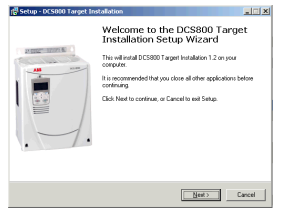
If the installation routine does not start automatically:
- Go to Start/Run and browse for setup.exe on the CD. Now start
the installation by confirming with OK
- Compact installtion for DriveWindow Light + Commsioning
Wizard + DriveWindow Light AP is reccomended

Steps to connect Drive to PC
• The documentation can be found under
C:ABBDCS800Docu
• Remove design cover from the converter module
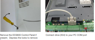
• Start DriveWindow Light PC tool
Check the communication setting of your COM port

If You use USB to COM port interface or PCMCIA / COM adapters double check the active COM enabled
Start => Settings => Control Panel => System => Hardware
=> Device Manager
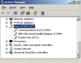
COM address of USB interface can change after the next boot
procedure or after disconnecting and reconnecting of the USB
interface.
Note:
PCMCIA to COM Port provide a stable and faster drive interface.
Utilize DriveWindow Light or DCS800 Panel Wizard continue
with chapter Commissioning in this manual.
For commissioning by DriveWindow find a workspace description in the DCS800 Firmware manual.
Danger! High voltage: this symbol warns of high
voltages which may result in injuries to persons
and/or damage to equipment. Where appropriate,
the text printed adjacent to this symbol describes
how risk of this kind may be avoided.
General warning: this symbol warns of non-electrical risks and dangers which may result in serious
or even fatal injuries to persons and/or damage to
equipment. Where appropriate, the text printed
adjacent to this symbol describes how risk of this
kind may be avoided.
General instructions
• This short commissioning refers to Chapter 5 Connection examples of this publication.
• Safety and operating instructions - see chapter 6
of this publication.
• Recommendations for motor and field voltages see
Technical catalogue.
• In accordance with DIN 57 100 Part 727 / VDE 0100
Part 727, precautions must be taken to enable the
drive to be shut down, e.g. in the event of danger.
The unit’s digital inputs or the control panel are not
sufficient as the sole measure for this purpose!
Warning of electrostatic discharge: this symbol
warns you against electrostatic discharges which
may damage to unit. Where appropriate, the text
printed adjacent to this symbol describes how risk
of this kind may be avoided.
NEC motor overload protection
The DCS800 provides a solid-state motor overload
protection in accordance with the NEC. The overload
protection (e.g. protection level in percent of full-load
motor current) can be adjusted by parameters in
group 31 and group 99.
The instructions can be found in chapter Motor
thermal model of the DCS800 Firmware manual.
Preparations
• Check unit for any damage!
• Install unit and wire it up
• Supply voltage level / Rated value correct for electronics and fan?
• Supply voltage level / Rated value correct for armature-circuit converter?
• Supply voltage level / Rated value correct for field
supply?
• Wiring / cross-sections, etc. correct?
• EMERGENCY STOP functioning properly?
• COAST STOP functioning properly?
Standard Features
• kompakt
• Höchste Leistungsfähigkeit
• Einfachste Bedienung
• Komfortable Assistenten, z. B. zur Inbetriebnahme
oder Fehlersuche
• Skalierbar für alle Anwendungen
• Frei programmierbar dank eingebauter IEC61131-SPS
DCS800 Gleichstromantriebe
Technische Daten DCS800
Nennanschlusssp. 230 bis 1.200 V
+/–10%, 3~
Frequenz 50 bis 60 Hz +/–5 Hz
Elektronikspg. 115 bis 230 V
–15% / +10%, 1~
DC Ausgangsstrom 20 bis 5.200 A
Überlastbarkeit 200%
Umgebungsgrenzwerte
Umgebungstemp. 0° bis +40° C
40°bis 55°C
Stromreduktion
Lagertemperatur –40° bis +55° C
Transporttemp. –40° bis +70° C
Relative 5 bis 95%, nicht
Luftfeuchtigkeit kondensierend
max. 50% zw. 0° und
5° C
Verschmutzungsgrad Klasse 2
Schutzgrad IP 00
Betriebshöhe bis 1.000 m üNN
Nennstrom
Über 1.000 m üNN
Stromreduktion
Ein-/ Ausgänge
Digitale Eingänge 8 Standard,
bis 14 optional
Digitale Ausgänge 8 Standard,
bis 12 optional
Analoge Eingänge 4 Standard
+/–10 V; 0/2…10 V bis 8 optional
+/–2 0mA; 0/4…20 mA
Analoge Ausgänge 3 Standard
(1x Iist) +/-10 V; 0/2…10 V bis 7
optional –20 mA; 0/4…20 mA
PC-Tools
DriveWindow Light
kostenlos mit jedem Antrieb,
Standard RS232 Verbindung
DriveWindow Echtzeit optische
Verbindung
ControlBuilder DCS800
IEC61131 Programmierung
DriveSize Antriebs- und
Motorauslegung
Wartung / Diagnose
Fernwartung von jedem InternetPC aus
• mit Internet Browser / Internet
Explorer
• oder mit DriveWindow Vollzugriff
via OPC
Zulassungen
Adaptive Programmierung
fertige antriebsspezifische
Blöcke, darunter
• Freier Prozessregler (PI-Regler)
• Ein/Ausgänge
Mit Bedien-Panel oder PC-Tool,
ohne zusätzliche Hardware
Drehzahlrückführung
EMK
Analoger Tachometer
Inkrementalgeber
Zweiter Inkrementalgeber möglich
(RTAC)
Kommunikation
Verfügbare serielle Schnittstellen
• Ethernet • Profibus
• CANopen • DeviceNet
• ControlNet • DDCS
• Modbus
• CS31 • AF100
• Selma2
Industrial IT© enabled
DCSLink Peer-to-Peer
• bis 800 kBaud, < 2,5 ms
• Master-Follower
• Anker-Feldstromrichter
• frei definierbare Daten
Hochstromlösungen
• 12-puls bis 20.000 A, seriell und
parallel
• Hart parallel und sequenziell
• bis 1.500 V
Schutzfunktionen
Tachosignalüberwachung • Temperatur • Überlast • Überdrehzahl
• Motor blockiert • Motorüberstrom • Motorüberspannung •
Feldüberstrom • Feldüberspannung • Mindestfeldstrom • Drehzahl Null • Ankerstromwelligkeit •
Netz Über- und Unterspannung
Integrierte IEC 61131-SPS
• Offenes Programmiertool
ControlBuilder DCS800
• Unterstützung aller fünf IECSprachen
• Antriebsspezifische
Funktionsblöcke
• Speicherung in Memory Karte
• Online Debugging und Forcing
Kurzanweisung CD und Dokumentationsübersicht
Wir freuen uns, dass Sie einen ABB DC-Stromrichter erworben haben und bedanken uns für das Vertrauen, welches
Sie unseren Produkten entgegengebracht haben.
Damit Sie auch weiterhin mit unserem Produkt zufrieden sind,
haben wir diese Broschüre für Sie zusammengestellt. Sie
soll hauptsächlich dazu dienen, ihnen einen kurzen Überblick
über das Produkt, EMV Hinweise, typische Anwendungen,
Inbetriebnahme und Fehlersuche zu verschaffen.
Benötigen Sie weitere Informationen zum Produkt, wurde
zusätzlich mit dieser Broschüre eine CD-ROM geliefert.
Die CD-ROM ist Teil dieser Broschüre und hat folgende
Bestandteile:
Dokumentation
Unsere Dokumentation ist folgendermaßen aufgebaut:
Technischer Katalog (3ADW000192)
als umfassende Information zur Planung kompletter DCStromrichter.
Hardware Handbuch (3ADW000194)
als Detailinformation mit allen wichtigen Angaben zu
den Einzelkomponenten, wie z.B. Modulabmaße, Elektronikkarten, Lüfter und Zusatzkomponenten.
Informationen über die mechanische- und elektrisch Installation sind auch enthalten.
Firmware Handbuch (3ADW000193)
Detailinformation mit allen wichtigen Angaben zur Firmware
und Einstellungen der Parameter. Dieses Handbuch enthält
mit allen notwendigen Informationen zur Inbetriebnahme.
Außerdem sind sowohl alle Fehler- und Alarmmeldungen
aufgelistet als auch Informationen zur Fehlersuche.
Service Manual (3ADW000195)
für die Wartung und Reparatur der Stromrichter.
Applikationen
Der DCS800 DC-Stromrichter kann auch Applikationsprogramme enthalten z.B. für Kräne und Wickler. In solchen Fällen
ist es möglich, daß die folgenden Anweisungen oder diverse
Assistenten entweder gesperrt sind oder nicht beendet werden können. Bitte mit Hilfe weiterführender Dokumentation
überprüfen (siehe auch Parameter 4.03 und 83.01).
Weitere Informationen über Applikationen (z.B. 12-Puls)
und technisches Zubehör (z.B. Hardwareerweiterungen oder
Feldbusadapter) werden in separaten Handbüchern behandelt. Siehe Tabelle DCS800 Antrieb Handbücher.
Systemvoraussetzungen für die Nutzung
der CD ROM
• Betriebssystem WINDOWS
2000, XP
• ACROBAT READER 4.0
ist ausreichend (empfohlen
wird 8.0 - auf der CD ROM
enthalten)
In case the CD ROM does not start automatically please
double-click on Setup.exe.
Weitere Unterstützung
Wir bieten Ihnen darüber hinaus weitere Unterstützung an,
denn nur wenn Sie als Kunde mit uns und unseren Produkten
zufrieden sind, können auch wir zufrieden sein.
Internet
Auf der ABB Homepage unter
www.abb.com/dc
finden Sie viele Informationen zu
• DC Produkten
• Service
• neueste Updates
• Anwendersoftware
• Downloads etc.
Bitte zögern Sie nicht uns dort zu besuchen.
Kontakte
Benötigen Sie weitere Informationen, sprechen Sie bitte Ihr
nächstgelegenes ABB Drives Büro an oder schreiben Sie
eine E-Mail an:
DC-Drives@de.abb.com
Geben Sie bitte Ihren Namen, Ihre Firmenadresse und Telefonnummer an und wir werden Ihnen umgehend den für
Sie zuständigen Ansprechpartner mitteilen.
-
 Hirschmann RS20-1600M2T1SDAEHH03.1.02 Rail Switch
 -
 Hirschmann BRS30-24TX Industrial Rail Switch
 -
 Hirschmann RSPM20-4T14T1EV9HHS999.9.99 Managed Ethernet Switch
 -
 Hirschmann BELDEN RS40-0009CCCCSDAPHH09.0.14 / RS400009CCCCSDAPHH09014
 -
Hirschmann RS40 Rail Switch RS40-0009CCCCSDAE
-
 Hirschmann BELDEN RS30-0802T1T1SDAP / RS300802T1T1SDAP Fully Managed Layer 2 Compact Rail Switch
 -
 Hirschmann BELDEN RS20-0800M2M2SDAUHH / RS200800M2M2SDAUHH
 -
 Hirschmann EAGLE30-04022O6TT999SCCY9HSE3F Industrial Firewall Router Switch
 -
 Hirschmann RS20-1600T1T1SDAEHH09.0.14 RS20 Rail Mount Ethernet Switch
 -
 Hirschmann EAGLE0200T1T1TDDY90000HHE05.3.03 Industrial Security Router
 -
Hirschmann - BELDEN MIPP-AD-1L9P
-
 HIRSCHMANN RSPM20-4Z64Z6TV9HHS9 942 106-999 RAIL SAFETY SWITCH
 -
 HIRSCHMANN FIBEROPTIC MODULE FIP P/N: OZDFIPG3T
 -
 HIRSCHMANN RS20-1600M2M2SDAUHH Ethernet rack-mounted switch
 -
 HIRSCHMANN BELDEN RS20-0400T1T1SDAEHH04.0.01 / RS200400T1T1SDAEHH04001
 -
HIRSCHMANN MM2-4FXM3 MICE Media Module
-
HIRSCHMANN RS20-0800M2M2SDAE Industrial Ethernet Rail Switch
-
 Hirschmann RS20-2400T1T1SDAP / RS20-2400T1T1SDAPHH05.0.02
 -
 GE MLJ1005B010H00C MLJ Digital Synchromism Check
 -
 ALSTOM MICROTECH DX21-M2 Digital Excitation Controller
 -
HIRSCHMANN BRS20-1200ZZZZ-STCY99HHSES
-
 HIRSCHMANN MM3-4FXM2 MICE Media Module
 -
Hirschmann RSB20-0800T1T1SAABHH 8Port ENet Rail Switch RSB20
-
 Hirschmann MACH102-8TP Ethernet Switch
 -
 SAACKE DDZ-M marine steam pressure atomizer
 -
 SAACKE SKV-A marine rotary cup atomizer
 -
 SAACKE Seavis HMI05e
 -
 Kollmorgen MMC-SD-2.0-230 Servo Drive 100-240VAC 2KW 10A Output 3PH 100-240VAC
 -
 Kollmorgen Servo drive CR10550
 -
 Kollmorgen AKD-P01207-NACN-0054 Servo Driver
 -
 Kollmorgen S406M-CA-036 Servostar
 -
.png) Kollmorgen AKD-B02407-NAAN-0000 Digital Servo Drive
Kollmorgen AKD-B02407-NAAN-0000 Digital Servo Drive -
 Kollmorgen SERVOSTAR S406AM-CA Digital Servo Drive
 -
 KOLLMORGEN SERVOSTAR 603-AS SERVO AMPLIFIER_SERVOSTAR603AS_S60301
 -
Kollmorgen S700 Servo Controller (S70602-NANANA-NA)
-
 Kollmorgen MPK411 controller
 -
 KOLLMORGEN MMC-SD-1.3-460-D Smart Drive
 -
 KOLLMORGEN AKM21C-CKB2AA-00 / AKM21CCKB2AA00 Servomotor
 -
 BECKHOFF AX5106-0000-0200 | Digital Compact Servo Drives 1-channel
 -
 BECKHOFF C3620-0000 INDUSTRIAL COMPUTER (MOTORSHELVES)
 -
 Beckhoff EK1960-0000 TwinSAFE Compact Controller
 -
 Beckhoff C6930-0050 Control Cabinet Industrial PC
 -
 Beckhoff CP7711-0001-0030 Industrial Computer Detection
 -
 Beckhoff CX1001-0111 Embedded PC CPU Module
 -
 Beckhoff C6017-0020 | Ultra-compact Industrial PC
 -
 Beckhoff EK1322 | 2-port EtherCAT P junction with feed-in
 -
 Beckhoff CP2219-0010 Panel
 -
 BECKHOFF C6015-0020 ULTRA COMPACT INDUSTRIAL PC
 -
 BECKHOFF CX2030-0120/Standard CPU Module Embedded PC Windows PLC controller
 -
 Beckhoff CP7721-1090-0020 Panel PC
 -
 Beckhoff PC CPU Module CX5130-0175
 -
 Beckhoff C6920-0050 Control Cabinet
 -
 Beckhoff EL6631 EtherCAT 2-Port Communication Interface, Profinet RT Controller
 -
 Beckhoff CP6202-0001-0060 touch screen panel PC
 -
 Beckhoff CP3916-1002-0000 Multi-Touch Control Panel
 -
 Beckhoff EP1809-0021 | EtherCAT Box, 16-channel digital input, 24 V DC, 3 ms, M8Preferred type
 -
 Beckhoff CX8190 PLC Embedded Industrial PC Ethernet Controller
 -
 Beckhoff CX2100-0914 Power Supply for External
 -
 Beckhoff Automation CP6906-0001-0000 HMI
 -
 Beckhoff EP7342-0002 Module
 -
 Beckhoff CX1020-0112 / CX1100-0910 / CX1020-N010 / CX1100-0003 Windows CPU
 -
 Beckhoff EP7211-0034 EtherCAT Box 1 Channel Motion Interface
 -
 Beckhoff C6240-0030 Control cabinet Industrial PC
 -
 beckhoff motherboard CB1052-0004 CB1052-0004
 -
 Beckhoff AX2006-AS Servo Drive / Variable Frequency Drive
 -
BECKHOFF CP6207-0001-0020 NSMP
-
 Beckhoff C6930-1142-0060 Industrial Computer
 -
 Beckhoff FC7501-0000 interface card
 -
 Beckhoff CX5140-0175 Embedded PC PLC CPU CX5140 Industrial Controller
 -
 Beckhoff CP7802-1100-0010: High-End IP65 Control Panel with DVI/USB Extended Interface
 -
BECKHOFF CP3716-1058-0010 CONTROL PANEL
-
 Beckhoff AX8108-0000 Single-Axis Module
 -
 Beckhoff CU8851-0000 | USB extension, USB Extended 2.0 receiver box
 -
Beckhoff C6017-0030 | Ultra-compact Industrial PC
-
 Beckhoff CX1001-0120/CX10010120.cx1000-n001.cx1000-n000 System Overview
 -
 Beckhoff CPU Module CX5140-0155/4GB CPU Module
 -
 Beckhoff CP6533-0001-005: Built-in Panel PC with High-Definition Multi-Touch Control
 -
 Beckhoff EL5042 | EtherCAT Terminal, 2-channel encoder interface, BiSS® C
 -
 Beckhoff C6920-1080-0040: Premium Control Cabinet Industrial PC
 -
 Beckhoff C6920-0060 | Control cabinet Industrial PC
 -
 Beckhoff Embedded-PC CX5010-1121
 -
 Beckhoff CB3050-0010 Mainboard Motherboard
 -
 Beckhoff PLC module CX1020-0000 Basic CPU module (service phase)
 -
 Beckhoff CP7812-1056-0010 15" Multitouch Display Control Panel
 -
 Beckhoff CX5120-0115 /2GB Controller Module
 -
 Beckhoff CP7201-1000-0000 Industrial Panel PC
 -
 Beckhoff Servo Motor AM8061-0JH1-0000
 -
 BECKHOFF CP6503-0001-0050 Built-in Panel PC
 -
Beckhoff CP3919-0010 Display G190ETN01.2 19" PCT V04. Multi-touch Control Panel
-
 Beckhoff CX5110-0112-9020/000368201 Embedded PC Intel Atom Processor
 -
 Beckhoff AX8206-0000 Dual-Axis Module
 -
Beckhoff Nail Operating Terminal CP7032-1031-0010
-
Beckhoff AM8042-0EH1-0000 Servomotor 4.10 Nm (M0), F4 (87 mm)
-
 Beckhoff EK9300 Beckhoff CPU Module
 -
Beckhoff CP3224-0020 Multitouch-Panel-PC
-
 Beckhoff CP2712-0000 12.1" 24VDC Touch Screen WMD0
 -
 BECKHOFF CX5240-0195 / 0000289234 Embedded PC 40 GB CFast Card
 -
 Beckhoff CP6932-1000-0000 Control Panel
 -
 BECKHOFF CX5120-0121 PLC Module
 -
 Beckhoff EL3218 | EtherCAT Terminal, 8-channel analog input
 -
Beckhoff C6640-0050 | Control cabinet Industrial PC
-
 Beckhoff Cx5130-0120/4GB Embedded-PC
 -
 BECKHOFF CX2030-0122 PLC PROCESSOR
 -
 BECKHOFF CX5020-0122 Controller Module
 -
 Beckhoff CP3915-0000 Multitouch Panel
 -
 BECKHOFF EL3014 | EtherCAT Terminal
 -
 BECKHOFF Industrial Computer c6920-1057-0030
 -
 Beckhoff CX5130-0141/4GB CX5130-0141 Embedded PC
 -
 Beckhoff C6240-1052-0040 4-086-06-3073 Industrial Computer
 -
 Beckhoff CX5140-0135 /4GB High-Performance Embedded Industrial PC
 -
 Beckhoff C6515-1001-0000 Industrial PC
 -
 Beckhoff AX5103-0000-0200 - Digital Compact Servo Drives
 -
 Beckhoff CX2030-0130-1003/4GB Basic CPU module
 -
 Beckhoff AX8620-0000 Power Supply Module
 -
 Beckhoff CX9020-0111 module with
 -
 Beckhoff EL7332 PLC Module
 -
 BECKHOFF CP7709-0001-0020 HMI
 -
 Beckhoff CX5120-0155/2GB Embedded PC
 -
 BECKHOFF CP7037-1037-0010 OPERATOR INTERFACE TOUCHSCREEN
 -
 Beckhoff EK9000 | ModbusTCP/UDP Bus Coupler
 -
 Beckhoff Touch Panel Screen CP6020 -0000-0000
 -
 Beckhoff CX2020-0121 Module FAST Shipping
 -
 Beckhoff CX2030-0125 Basic CPU Module
 -
 Beckhoff CP3918-0000 Multi-Touch 18.5" Control Panel
 -
 Automotion LC4A00010 DC BL Motor Control, ATS, Sub Assy, SCP, 115VAC,
 -
 500T-115VAC - VAS ENGINEERING - DORIC 500 SERIES DIGITAL TEMP INDICATOR
 -
 Honeywell X-DCS2000/EN Digital Integrated System Manager 50/60Hz 100-240V #4
 -
 Kollmorgen S60600 Servostar600 606-Fan 4 kVA, 6 A, 3 X 230 - 480 V


