
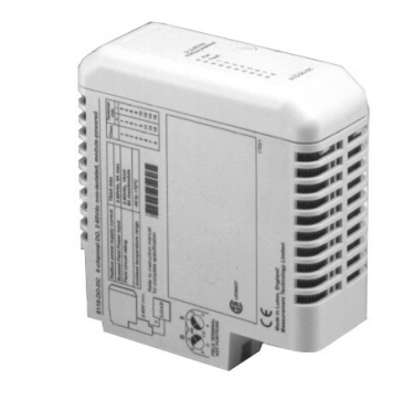
ABB NextMove ESB-2
# Summary of ABB NextMove ESB-2 Motion Controller User Manual
This manual comprehensively introduces the features, installation, configuration, operation, and maintenance of the ABB NextMove ESB-2 multi-axis intelligent motion controller. The following is a summary of key points:
## I. Overview and Safety Information
### 1. Controller Features
The NextMove ESB-2 is a high-performance multi-axis controller supporting servo and stepper motor control. Its core features include:
- Supporting **3-4 servo axes** and **4 stepper axes** (model-dependent), with additional encoder inputs for master-follower applications;
- Integrating the Mint motion control language (a structured form of Basic, suitable for both simple and complex motion scenarios);
- Rich I/O configuration: 20 digital inputs, 12 digital outputs, 2 channels of 12-bit differential analog inputs, and 4 channels of 12-bit analog outputs;
- Communication interfaces: USB 1.1, CANopen/Baldor CAN protocols, and RS232/RS485 serial ports;
- Supporting various motion types such as jogging, software cams, and gear synchronization, and can directly replace the NextMove ESB.
### 2. Safety Precautions
- Only qualified personnel should operate the equipment to avoid high-voltage electric shock and electrostatic damage (ESD protection is required);
- The equipment may be connected to rotating parts, and improper use may cause injury. The stop input cannot be used as the sole means of safe shutdown;
- Electromagnetic fields may affect medical devices (such as pacemakers), and relevant personnel must stay away from motors and current-carrying conductors;
- Compliance with local safety standards is required (such as the EU Machinery Directive, US NEC, etc.).
## II. Model and Receiving Inspection
### 1. Model Differences
Different models vary in the number of servo axes, serial port types, and stepper output types. Key model parameters are as follows:
| Model Example | Number of Servo Axes | Number of Stepper Axes | Additional Encoder Inputs | Serial Port Type | Stepper Output Type |
|----------------|----------------------|------------------------|---------------------------|-------------------|----------------------|
| NSB202-501 | 3 | 4 | 2 | RS232 | Differential (RS422) |
| NSB203-502 | 3 | 4 | 2 | RS485 | Open Collector |
| NSB204-501 | 4 | 4 | 1 | RS232 | Differential (RS422) |
| NSB205-502 | 4 | 4 | 1 | RS485 | Open Collector |
### 2. Receiving Inspection
- Check the integrity of the packaging and report transportation damage;
- Verify that the model matches the order and record the serial number;
- Long-term storage must meet environmental requirements (see 7.1.11 for humidity and temperature).
## III. Installation Requirements
### 1. Environmental and Mechanical Installation
- Installation location: Indoor and fixed, avoiding heat sources, corrosive substances, and dust. Temperature range: 0-45°C; humidity: ≤80% (below 31°C) to 50% (at 45°C);
- Mechanical fixing: Use M4 screws to mount on a vertical non-flammable surface, with heat dissipation slots reserved at the bottom. At least 20mm of heat dissipation space around, and additional 70mm space at connectors.
### 2. Power and Equipment Requirements
- Power supply: +24V DC (2A continuous power supply), with a recommended independent 4A fuse for protection;
- Supporting PC requirements: 1GHz processor, 512MB RAM, 2GB hard disk, USB/serial port, 1024×768 screen, supporting Windows XP and above.
## IV. Input/Output (I/O) Configuration
### 1. Analog I/O
- **Analog inputs**: 2 differential inputs (±10V, 12-bit resolution, 120kΩ impedance, maximum 4kHz sampling rate), supporting single-ended/differential wiring;
- **Analog outputs**: 4 bipolar outputs (±10V, 12-bit resolution, maximum 2.5mA output), used for servo drive demand signals, requiring shielded twisted-pair cables.
### 2. Digital I/O
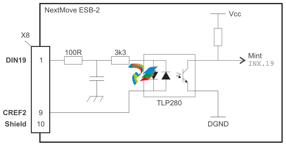
- **Digital inputs**: 20 opto-isolated inputs, divided into 3 groups (DIN0-3 are high-speed interrupt inputs with 1μs response; DIN4-11/12-19 are general inputs), configurable for level/edge triggering;
- **Digital outputs**: 12 outputs (total current 500mA for DOUT0-7, 500mA for DOUT8-11), supporting drive enable and global error output. Inductive loads require freewheeling diodes.
### 3. Special I/O
- **Stepper control outputs**: 4 outputs (0-500kHz). Differential models (NSB202/204) use RS422 drivers; open-collector models (NSB203/205) use ULN2803;
- **Encoder inputs**: 5 incremental encoder inputs (A/B/Z differential signals, MAX3095 receiver), supporting 10MHz quadrature counting. Cable length affects maximum frequency (e.g., 1.3MHz for 2m, 7kHz for 1000m);
- **Relay**: 1 relay output (1A@24V DC or 0.25A@30V AC). COM connects to NO under normal conditions and to NC in case of faults;
- **Communication interfaces**: USB 1.1 (compatible with 2.0/3.0, maximum 5m cable), RS232/RS485 (up to 115.2Kbaud), CAN (RJ45 interface, supporting CANopen/Baldor CAN, requiring 12-24V power supply).
## V. Operation and Configuration
### 1. Software Installation and Connection
- Install Mint WorkBench (requires administrator privileges) and connect the controller via USB or serial port;
- Power-on check: The status display shows the node number (blinking by default). Faults are indicated by 0-7 with a decimal point, requiring reference to troubleshooting.
### 2. Axis Configuration
- **Axis type selection**: Set axes as servo/stepper/virtual via the Axis Config Wizard and assign hardware channels;
- **Scale factor (SCALEFACTOR)**: Convert encoder counts to user units (e.g., revolutions, millimeters). For example, a 1000-line encoder set to 4000 represents 1 revolution;
- **Drive enable output**: Configure digital outputs or relays as drive enables and test enable state switching.
### 3. Testing and Tuning
- **Stepper axis testing**: Use the `JOG(0)=2` command to test forward and reverse rotation and adjust speed parameters;
- **Servo axis testing**: Use the `TORQUE(0)=5` command to test demand output and observe speed/position via the Spy window;
- **Closed-loop control tuning**:
- Proportional gain (KPROP): Improves response speed; excessive values cause oscillation;
- Derivative gain (KDERIV)/velocity feedback (KVEL): Increases damping and reduces overshoot;
- Integral gain (KINT): Eliminates steady-state errors, requiring an integral limit (KINTLIMIT);
- Velocity feedforward (KVELFF): Reduces following errors, calculated as 2048/(quadrature counts per servo cycle).
### 4. Configuration Saving
Generate a Startup Block via Mint WorkBench, save the configuration to a file, and load it for future use.
## VI. Troubleshooting
### 1. Status Display Meanings
- Node numbers 1-15 are displayed in hexadecimal; numbers >15 are displayed as three horizontal lines;
- Fault codes: 0-7 with a decimal point indicate startup faults, requiring contact with technical support;
- Axis status symbols: e.g., "J" for jog, "E" for error, "S" for stop.
### 2. Common Issues
- **Communication problems**: Check power supply, cable wiring, USB driver installation, and power cycle after firmware update;
- **Motor not rotating**: Check drive enable configuration, wiring, and servo gains;
- **Motor runaway**: Verify common grounding, encoder feedback polarity, and whether the drive input is 0V at zero demand;
- **CAN issues**: Ensure termination resistors (120Ω) are only connected at both ends, consistent baud rates, and unique node IDs.
## VII. Technical Parameters and Accessories
### 1. Core Parameters
- Power supply: 24V DC±20%, power consumption 50W;
- Environment: Operating temperature 0-45°C, humidity ≤80% (non-condensing), altitude ≤2000m;
- Dimensions: 245×140×45mm, weight ~700g.
### 2. Accessories
- Feedback cables (CBL015MF-E3B, etc., maximum 30.5m);
- Baldor CAN nodes (input/output/relay nodes);
- HMI panels (character/touchscreen, supporting serial/CANopen);
- Mint NC software (converts CAD to motion control code). 
-
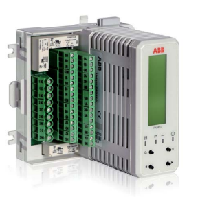
 ABB NIAMO1 PLC Module
 -
 HIMAcard F8650X
 -
 HIMA F8652 98465266 PLC Module
 -
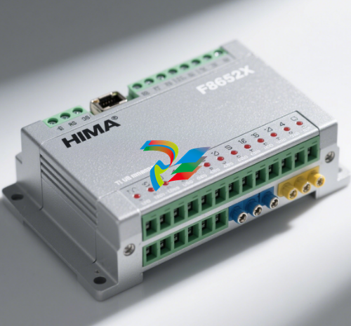 F8652X HIMA Central module
 -
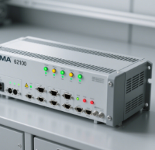 HIMA 62100
 -
 HIMA 99-7105233 B5233-1 NSMP
 -
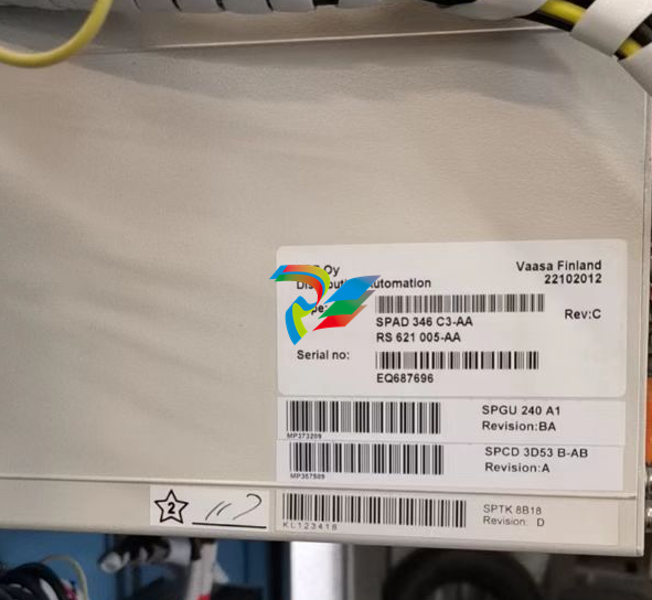 ABBSPAD 346 C3-AA
 -
 ABBREF543KM127BABB
 -
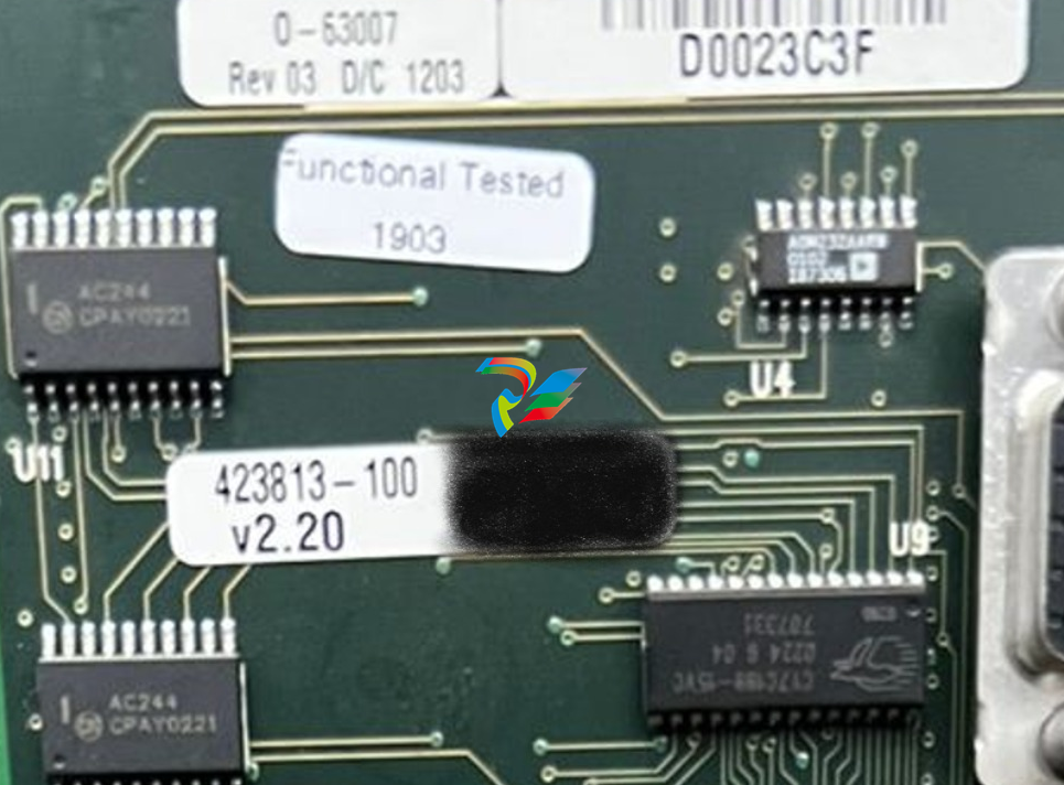 ABB 0-63007 M003742626
 -
 Abb FET3251A0P1B3C0H2M
 -
 ABB 3HAB8800-1
 -
 ABB 3AUA266001B166
 -
 ABB3HNM07686-1
 -
 ABB PQF4-3 TAS
 -
 Honeywell 30735863-502 - SWITCH
 -
 Honeywell TK-CCR014 - REDUNDANT NET INTERFACE NEW ORIGINAL FREE EXPEDITED SHIPPING/
 -
 Honeywell 51403165-400 - new 51403165400/
 -
 Honeywell318-049-001 quot100 Batteries(Japan Liion2Ah14.8Wh)INTERMEC/ PR2,PR3 P/N
 -
 Honeywell FC-PSU-UNI2450U - Power Supply
 -
 Honeywell 965-0676-010 - WARNING COMPUTER SV
 -
 Honeywell 51403519-160 - Module
 -
 Honeywell 107843 - HOUSING CARBON FILE P/N NE COND # 11438 (4)
 -
 Honeywell VR434VA5009-1000 - Brand new in box Condensing boiler valve DHL fast shipping
 -
 Honeywell SPXCDALMFX - plc new FREE EXPEDITED SHIPPING/
 -
 Honeywell BCM-PWS - BCM-ETH BCM-MS/TP BCM-MS/TP Network controller setFedEx or DHL
 -
Honeywell YSTR12D-22/C/-2J0DFA/BE/400/T/-CM.HO.TG.SB.SM,ZS,F1,LP,/FX/,1C-BT - UNMP
-
 Honeywell IWS-1603-HW - 90-250VAC 1.0A UNMP
 -
 Honeywell 51304386-150 - MEASUREX Factory Packed
 -
 Honeywell CC-IP0101 - Profibus Gateway Module
 -
Honeywell CC-PFB401 - / CCPFB401 (NEW IN BOX)
-
 Honeywell 50071726 - St 800 Series Pressure Transmitter Remote Diaphragm 11-42VDC
 -
 Honeywell 621-2150 - / 6212150 (NEW NO BOX)
 -
 Honeywell 80360206-001 - USED YAMATAKE CLI BOARD
 -
 Honeywell BMDX001A-001 - ACCURAY / BOARD BMDX001A001
 -
 Honeywell XCL8010A - New CPU Controller.
 -
 Honeywell PGM-7320 - 1PCS NEW Rae Systems MiniRAE 3000 Portable VOC Monitor#XR
 -
 Honeywell BK-G40 - U65 *FULL INSTALLATION* Gas Meter 3?± Inlet/Outlet Spool NEW UNUSED
 -
 Honeywell DM106-0-B-00-0-R-1-00000-000-E0 - DPR100 250V NSNP
 -
 Honeywell KFD840 - PRIMARY FLIGHT DISPLAY CORE PN: 066-01206-0104
 -
 Honeywell 51401914-100 - 51400996-100
 -
 Honeywell TK-PRS021 - Module Via FEDEX/DHL
 -
 Honeywell C7012A1145 - 1PC New UV Flame Detector Expedited Shipping
 -
 Honeywell OV210 - Baxter Bakery Oven Igition Control. For DRO. 00-616973 NEW
 -
 Honeywell 51304431-125 - 1PC New /51304431125 1 year warranty#XR
 -
Honeywell QPP-0002 - Quad Processor Module / 5 Vdc / Massima 1.2A/24Vdc/max.25mA
-
Honeywell QPP-0002 - Quad Processor Module / 5Vdc / Max. 1.2A/24Vdc/max.25mA
-
Honeywell 8C-PCNT02 - 514543363-275 module
-
Honeywell DPCB21010002 - Tata Printed Circuit Board
-
 Honeywell DPCB21010002 - Tata Printed Circuit Board Rev: 0
 -
 Honeywell 001649-M5T028 - Tata Printed Circuit Board Rev: 0
 -
Honeywell YSTD924-(J2A)-00000-FF,W3,TP,TG,SS - NSFS
-
 Honeywell XF523-A - / XF523A (NEW IN BOX)
 -
Honeywell TK-PRS021 - NEW IN STOCK ship by UPS
-
 Honeywell 2MLR-AC22 - " 2mlr-dbsf,2mlf-ad4s,2mlf-dc4s,2mlr-ac22 Rack"
 -
 Honeywell 9436610 - MEASUREX NSMP
 -
 Honeywell RT10A-L0N-18C12S0E - RT10A.WLAN.IN.6803.CAM.STD.GMS
 -
Honeywell 51305896-200 - P:C1 Rev D Nim Modem - FAST SHIP BY Fedex
-
 Honeywell TK-FTEB01 - PCL module Brand New Fast Shipping By DHL
 -
 Honeywell 8694500 - Measurex Control Processor Module
 -
Honeywell DR4500 - Truline and DR4300 Circular Chart Recorder
-
Honeywell EC-7850-A-1122 - / EC7850A1122 (NEW IN BOX)
-
 Honeywell XNX-UTAI-RNNNN - NEW Universal transmitter DHL Fast delivery
 -
 Honeywell SPXCDALMFX - plc new One Year Warranty #
 -
Honeywell TC-RPFM01 - C200 system card brand new Fast Shipping
-
Honeywell 51196655-100 - NSMP
-
 Honeywell XCL8010A - / XCL8010A (USED TESTED CLEANED)
 -
 Honeywell 51198801-100 - NEW CPU INTERFACE BOARD UPGRADE KIT UPIU 51306154-100
 -
Honeywell 84795 - Sputtering Target 5N Al5Cu 7830x11640x13050
-
Honeywell W7704A-1004 - / W7704A1004 (USED TESTED CLEANED)
-
Honeywell RA890G1229 - FOR FSG UV Protectorelay /PL3
-
Honeywell KFS-599B - 071-01576-0101 UHF Communication Control with Mods (28V)
-
Honeywell WPC2000 - WINTRISS 9683001 WINTRISS CLUTCH/BRAKE CONTROL *NO KEYS*
-
Honeywell C7012E1112 - 1PC C7012E 1112 Burner Detector New In Box Expedited Ship #
-
 Honeywell 8C-TCNTA1 - C300 system card brand new Fast Shipping
 -
 Honeywell ANT67A - TCAS Antenna 071-01548-0100 w/ October 2023 Repaired 8130
 -
Honeywell CC-PDIS01 - PLC Module Brand New Fast Shipping FedEx or DHL
-
 Honeywell R7247C1001 - 2-4SECS NSMP
 -
 Honeywell ALI-80A - Collins Encoding Altimeter - P/N 622-3975-011 - Tested 8130 -Serviceable
 -
Honeywell 001650-M5T028 - Tata Relay Circuit Board
-
Honeywell 51196886-100 - PC BOARDS (126201 - NEW)
-
 Honeywell J-HAM10 - NSNP
 -
Honeywell TC-IXL062 - 1PCS module New fedex or DHL
-
 Honeywell 114M4910-6 - PISTON ASSY PN NS COND 12037
 -
Honeywell C7076 - 191002B Sensor Amplifier 220/240v
-
 Honeywell 510STR12D21A-B77P - NSNP
 -
Honeywell 51304511-200 - Module Nim Modem Via FEDEX/DHL
-
Honeywell IC-600 - Integrated Communication Unit RCZ851E 7510700-806 Removed Working
-
Honeywell TC-IAH161 - 1PC NEW REDUNDANT NET INTERFACE one year warranty#XR
-
Honeywell 2001-100-150-126-280-20-100000 - REMAN
-
 Honeywell QPP-0001 - FSC QUAD PROCESSOR PACK QPP MODULE CC V1.4
 -
Honeywell 30734558-001 - / 30734558001 (USED TESTED CLEANED)
-
 Honeywell STD830-E1HS4AS-1-A-ADB-11C-B-21A0-00-0000 - 4500PSI NSNP
 -
 Honeywell 900C75-0560 - NEW HC900 Controller module FedEx DHL Fast delivery
 -
Honeywell BL870 - Bezel 7014331-921 w/ October 2018 Repaired 8130
-
Honeywell STG77L-E1G000-1-A-CDC-11S-A-20A0-00-0000 - NSMP
-
Honeywell FF-SB14E12K-S2 - / FFSB14E12KS2 (USED TESTED CLEANED)
-
Honeywell 51198685-100 - "Rev. A, 140519-2-LF Power Supply Module 10A 100-240 VAC"
-
 Honeywell 942-M96-M - plc new FREE EXPEDITED SHIPPING
 -
 Honeywell TK-IAH161 - 1PC New ANALOG INPUT TKIAH161 Expedited Shipping
 -
Honeywell C7061F2001 - 1PC UV Flame Detector New In Box #
-
Honeywell 0190-20139/D - ONE Sputtering Coating Disc 4N5TI NEW
-
 Honeywell 82408667-001 - NEW MEMORY BOARD ROM/RAM 82408667001
 -
Honeywell C7012A1194 - NEW IN STOCK ship by UPS
-
 Honeywell TK-FTEB01 - NEW IN BOX FTE BRIDGE Brand New Fast Shipping FedEx or DHL
 -
Honeywell RA890G1344 - 1pc NEW Combustion Controller DHL or FedEX
-
Honeywell DH-AP-1/ - Miller 3 Workers per System 4-3/4 Ft Overall H Post Anchor
-
Honeywell TCOAV081 - NEW IN BOX ANALOG OUTPUT EXPEDITED SHIPPING
-
Honeywell W7704D1016 - Control Unit
-
 Honeywell 9437710 - USED PIDP MEASUREX / 09437710-RP MODULE REV D STOCK 1603
 -
Honeywell 51403165-400 - Brand new industrial computer Fast FedEx or DHL
-
Honeywell DC3200-EE-000R-240-00000-E0-0 - New DHL FastShip
-
 Honeywell 51305348-100 - / 51305348100 (USED TESTED CLEANED)
 -
Honeywell CC-PAIX01 - 1PCS Brand New Expedited Shipping
-
Honeywell 51305890-175 - REV B NEW
-
 Honeywell XCL8010A - NEW IN STOCK ship by UPS
 -
 Honeywell D18-UU0000-D00000-0000-2-0000-00-E - CHART RECORDER CHART RECORDER
 -
 Honeywell TC-IAH161 - ANALOG INPUT NEW 1PCS
 -
 Honeywell 10020/1/2 - / 1002012 (NEW IN BOX)
 -
Honeywell DC3200-EE-000R-240-00000-E0-0 - Digital Controller UPS Express New Zy
-
Honeywell 2MLR-CPUH/F - 1PC NEW EXPRESS P3097E YL/
-
Honeywell 9437710 - USED PIDP MEASUREX MODULE REV D STOCK 1608
-
Honeywell CC-PAIX02 - Fast Shipping
-
Honeywell DPR500 - Brand New Fast Shipping By DHL
-
Honeywell 10004/I/F - / 10004IF (USED TESTED CLEANED)
-
Honeywell C7012E1112 - 1PCS New in box UV Flame Detector
-
 Honeywell HPTZ-361W - Brand New Expedited Shipping
 -
Honeywell 10006/2/1 - / 1000621 (NEW NO BOX)
-
Honeywell SC-PCMX01 - 1PC NEW RTU2020 51307195-175 SHIP EXPRESS #P2254E YL

