
EMERSONTest Platform for Automation System
Abstract
There are different automation systems to control processes in industry. One of them is
DeltaV, which is a product from Emerson Process Management. Recently, Sandvik
Coromant, bought the DeltaV automation system for using it in production. To increase
the knowledge about DeltaV at Sandvik Coromant a project was initiated with the aim to
create a test platform and a course compendium for self learning. This thesis describes
how the test platform was developed and its functionality
Testplattform för styrsystemet DeltaV
Examensarbete vid Skolan för Elektro- och Systemteknik
Sammanfattning
För att styra processer i industrin finns det olika styrsystem. Ett av dessa är DeltaV, som
är en produkt från Emerson Process Management. Nyligen köpte Sandvik Coromant
styrsystemet DeltaV för att använda det i sin produktion. För att öka kunskapen om
DeltaV på Sandvik Coromant initierades ett projekt: Att utforma en test plattform och ett
kurskompendium för självlärning. Denna uppsats beskriver hur tesplattformen har
utvecklats och dess funktionalitet.
Foreword
This report presents a Master’s project at the School of Electrical Engineering at the
Royal Institute of Technology (KTH) in Stockholm, Sweden.
The project has been performed at Sandvik Coromant in Västberga, Sweden. I want to
thank Sandvik Coromant for accepting me and Stefan Hedberg and Patrik Schütt for
their support throughout the project. I would also like to thank my supervisor, Professor
Håkan Hjalmarsson, at the School of Electrical Engineering, KTH, for his support.
I have performed this project in collaboration with Daniel Engdahl, who also is a member
of this project
Chapter 1
Introduction
Sandvik Coromant is the world's leading manufacturer of cutting tools for the
metalworking industry. Advanced production processes require advanced automation
systems for the control.
Production processes normally consist of a number of devices like valves, engines,
sensors, transmitters and controllers. These devices are controlled and monitored from
an automation system.
Sandvik Coromant has recently bought a new automation system, DeltaV, which is a
product from Emerson Process Management. To increase the knowledge about the
automation system at Sandvik Coromant, a project was initiated with the aim to create a
test platform and a course compendium for self learning.
This chapter describes the problem to be solved, the background to the automation
system DeltaV and gives the outline for the rest of the report.
1.1 Problem
In the following subsections the problem is described.
1.1.1 Task
The task in this project was to create a portable test platform for an educational purpose
for one of the automation systems, DeltaV from Emerson Process Management, that is
used at Sandvik Coromant. Along with the test platform, there should also be a course
compendium that describes how to learn DeltaV by using the test platform. The test
platform and the course compendium should together work as selflearning tools for the
personell at Sandvik Coromant. The platform should be small enough to be portable, so
that it can be brought to people who needs to learn DeltaV, independently of where they
are stationed.
Since the purpose of the task was not to learn how the production processes work, there
was not any requirement that the test platform should be similar to any process where
DeltaV is used at Sandvik Coromant. The only required similarity between the test
platform and the production processes at Sandvik Coromant was supposed to be that
similar measurement equipment was used.
1.1.2 Purpose
The DeltaV automation system has been used at Sandvik Coromant for two years. The
purpose of creating a test platform was to increase the knowledge of the automation
system among the personnel.
Since production processes are in general very costly to interrupt, a test platform was
needed to experiment with the functions of DeltaV. With the test platform the personnel
at Sandvik Coromant should be able to learn more about the automation system on their
own by testing how to control a physical process. The test platform along with the course
compendium should work as a selflearning tool.
1.1.3 Previous work
This is the first test platform and also the first course for DeltaV that has been developed
at Sandvik Coromant. The manufacturer of DeltaV, Emerson Process Management,
provides DeltaV courses. However, these courses do not come with a portable test
platform.
1.1.4 Description of the problem
The desire from Sandvik Coromant was to have a physical process, a software with
control algorithms for controlling the physical process and a course compendium on how
to learn DeltaV.
The requirement on the hardware in the physical process was that it should at least
include basically the same equipment as the production processes that are controlled
with DeltaV; relays, fuses, pressure transmitter, proximity sensors etc. Naturally, the
hardware should also include the automation system, DeltaV. The platform should be
small enough to be portable.
The requirement on the software part was similarly that it should at least include some
similar algorithms as the software for the real production processes includes. It was also
required that the software should include an operator interface in which an operator can
get the relevant information about the process; alarms indicating that something is
wrong, diagrams, an illustration of the process where the operator can follow what
happens etc.
The requirement on the course compendium was that a person who reads it should be
able to replicate the control software that was developed in this project. Persons taking
the course will have the original software as a key, which they should only use if they
experience significant problems.
Hence, to meet all requirement from Sandvik Coromant, the finished platform and
additional educational material should include the following:
• The DeltaV System with controller cards, I/O cards and fieldbus cards.
• Devices that are more or less the same as in the production processes at
Sandvik Coromant where DeltaV is used, for instance proximity sensors or
pressure transmitters.
• A software control system containing similar algorithms as the production
processes at Sandvik Coromant, for instance it might be of great relevance to
use a PID controller.
• An operator interface illustration that follows the physical process. The operator
environment should also contain an alarm list.
• A course compendium with both general information about functions in DeltaV
and instructions on how to create the same control system as the one which was
developed in this project.
1.1.5 Aim
The aim of this project was to make a test platform along with a course compendium.
The test platform should be portable so that it can be brought to people for education in
DeltaV regardless of where the persons are stationed. This education should give a
general knowledge on how to use DeltaV and after completing this course the engineers
should be able to implement simple control systems.
1.2 DeltaV-a DCS automation system
In industry there are different automation systems; some that are more basic and some
that are more advanced. This section will give an introduction to automation systems in
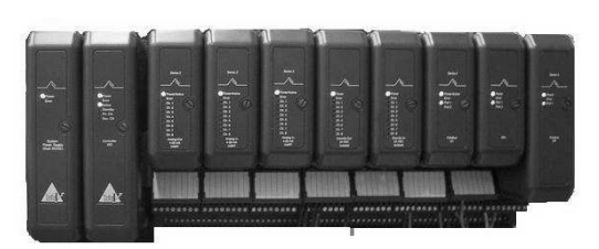
general and the specific automation system, DeltaV, that this project concerns. Figure
1.1 shows the hardware of the DeltaV automation system.
DeltaV is a DCS automation system. DCS is short for Distributed Control System and it
is and automation system that has evolved from PLC.[1]
PLC is short for Programmable Logic Controller. Originally PLC systems replaced old
automation systems that included many relays. PLC systems did then include only
discrete signals and when DCS was new, the difference between the two automation
systems was that DCS also included analog signals. However, today PLC includes both
analog and discrete signals and the difference between PLC and DCS is vague. Newer
designs look similar both in hardware and in software.[2]
The DeltaV automation system consists of one hardware part and one software part. In
the following subsections both parts willl be explained.
1.2.1 Controller, I/O and fieldbus cards
The hardware consists of controller cards, I/O cards and fieldbus cards.
In the controller a CPU is located and it is in the controller that the program containg
information on how to control the process is stored. This program is downloaded to the
controller from a workstation. The I/O cards and the fieldbus cards are capable of
sending or/and receiving signals to and from the devices. Hence, the I/O cards and
fieldbus cards send the signals that they get from the devices to the controller and the
signals that they get from the controller to the devices. The controller also sends
information to an operator interface, so that the operator of the process can monitor it.
Figure 1.2 shows an overview of the connections for an automation system.
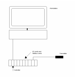
Figure 1.2. Overview of the connections for an automation system. A device is connected to an I/O card
or a fieldbus card. The controller communicates with the I/O cards and the fieldbus cards and is connected
to a workstation. The program is downloaded from a workstation to the controller.
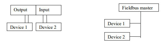
Figure 1.3. The network is reduced when using a fieldbus. Fieldbus cards allow communication in both
directions and the wiring is much less when using fieldbus cards.
In this project three fieldbus cards are used; Foundation Fieldbus, Profibus and ASInterface. Foundation Fieldbus and Profibus handle analogue signals and AS-i only
handles discrete signals.
The communication technology for all three fieldbus cards follows a standard model
called OSI (Open Systems Interconnection). An OSI model divides the functions of a
protocol into several layers. Each layer uses only the functions of the next layer, and
only exports functionality to the preceding layer. The main feature of the OSI-model is in
the interface between layers which dictates the specifications on how one layer interacts
with another. This enables that a layer written by one manufacturer can operate with a
layer from another. The OSI model contains seven layers, but the fieldbus model is only
based on three major layers (layers 1,2 and 7 in the OSI-model). [3]
AS-Interface (AS-i)
AS-i is the most simple fieldbus. It is designed for connecting binary devices.
The OSI-model consists of three layers; Transmission Control, Execution Control and
Application Layer Interface.
The Transmission Control includes the wiring of the field devices and other components
in the process. This layer receives messages and encodes them to physical signals.
The signals which are in NRZ code (non-return-to-zero code) are encoded using
Manchester II coding and then implemented with APM coding.
The principle of Manchester encoding is that every bit period has one transition in the
middle of the period. A positive transition represents a logic one and a negative
transition represents a logic zero. Transitions that are not in the middle of the bit period
do not carry any useful information. These transitions only have the purpose to set the
signal in the state where the mid-bit transition can take place.
With APM, pulses are created; a positive pulse is created at a low to high edge and a
negative pulse is created at a high to low edge. In figure 1.4 the coding principle for both
manchester encoding and APM is shown. [4][5]
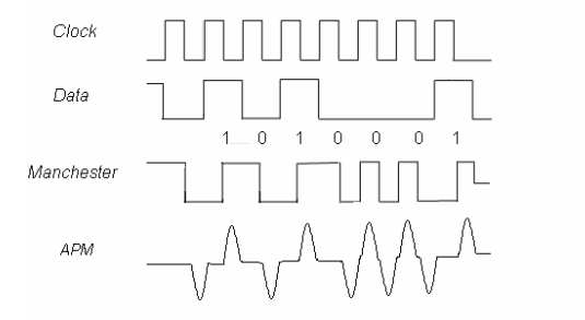
Figure 1.4. Illustration of the principle for the Manchester encoding and APM encoding. The data is coded
to Manchester code so that a transition occurs in the middle of every bit period. A positive transition
represents a logic one and a negative transition represents a logic zero. Transitions that are not in the
middle of the bit period do not carry any useful information. These transitions only have the purpose to set
the signal in the state where the mid-bit transition can take place.
The Execution Control is of Master/Slave characteristic. The AS-i card works as the
network master. The master automatically controls all communication over the AS-i
cable. The master interrogates all the available AS-i addresses and repeats the process.
The Application Layer Interface makes it possible to download the DI and DO functions
to the controller. This enables communication between the controller and the devices. [6]
Foundation Fieldbus
The Foundation Fieldbus card used in this project is H1. As compared to another
foundation fieldbus card H2, the H1 network is a lower speed and lower cost network
than H2.
The communication for foundation fieldbus follows the OSI model with three layers;
Physical Layer, Communication Stack and User Application.
The Physical Layer includes the wiring of the field devices and other components in the
process. This layer gets encoded messages from the next layers and converts them into
physical signals. The signals are encoded using the Manchester Biphase-L technique.
In manchester Biphase-L code a positive transition in the middle of a bit period
represents a logic zero and a negative transition in the middle of a bit period represents
a logic one, see figure 1.5.
Figure 1.5. Encoding with Manchester Biphase-L technique. In manchester Biphase-L code a positive
transition in the middle of a bit period represents a logic zero and a negative transition n the middle of a bit
period represents a logic one [5]
The Communication Stack is the layer that manages communication between a device
and a host or the communication between two devices.
In foundation fieldbus communication with H1, the H1 card works as a Link Active
Scheduler (LAS). A LAS is a deterministic, centralized bus scheduler that maintains a list
of transmission times for all the data buffers in all the devices that need to transmit in
cyclical fashion. [7] Field devices may also have Link Master capabilities and would in
the case that the H1 card fails, work as LAS. The H1 card is the only primary Link
Master allowed on the fieldbus segment. No other Link Master is allowed on the
segment or unpredictable results can occur. DeltaV supports one backup Link Master
device on each fieldbus segment.[8]
The communication between LAS and publishers and subscribers can be scheduled or
unscheduled.
Scheduled communication-The LAS maintains a list of transmit times for all data buffers
in all connected devices. When it is time for a device to transmit its data, the LAS sends
a CD (Compel Data) to that device. The device publishes (sends) data to all devices on
the fieldbus. The devices which are configured to receive the data are called
subscribers.
Unscheduled communication- These transmissions are done with PN (Probe Node) or
PT (Pass Token) and take place between transmissions of scheduled messages. The
LAS sends a PN (Probe Node) message to see whether any device changes have been
made. The changes are added to a live list. It is possible for a device to transmit
unscheduled messages after it has received a PT (Pass Token) from the LAS.
The User Application is a standard user application defined by Fieldbus Foundation.
This layer is not defined by the OSI-model. [9]
Profibus
The Profibus that is used in the test platform is Profibus DP (Decentralized Periphery).
Profibus DP is the most common Profibus.
The OSI-model for Profibus communication consists of three layers;
The Physical Layer defines the physical transmission characteristics. The signals are
sent using UART (Universal Asynchronous Receiver/Transmitter). With UART, data are
transmitted as streams of characters. Every character starts with a start bit (a 0) and
ends with a stop bit (a 1). The start bit allows the receiver to recoginize the start of a
new character and the stop bit makes sure that there will be a transition at the start of
the stop bit. [10]
The Communication Stack is a communication layer which defines the Bus Access
Protocoll. In a Profibus DP system the communication type is master/slave and both
multi-master and mono-master systems are possible. The protocoll used is Media Acces
Control (MAC), which specifies the procedure when a station is permitted to transmit
data on the bus. The MAC must ensure that only one station has the right to transmit
data at a time.
Hence, the requirements on the MAC protocol are that the following should be
accomplished:
• During communication between master stations it must be ensured that each of
these masters gets sufficient time to execute its communication tasks within a
precisely defined time interval.
• Cyclic, real time data transmission is to be implemented as fast and as simple as
possible for communication between a master and its slaves. [11]
The multi-master system manages communication by having a token that is sent
between the masters. When a master has the token, it can communicate with its slaves,
see figure 1.6. [12]
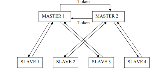
Figure 1.6. The multi-master communication of Profibus. The multi-master system manages
communication by having a token that is sent between the masters. When a master has the token, it can
communicate with the slaves.
The User Layer is defined as a standard user layer. [13]
1.2.2 Description of the Software tools in DeltaV
The automation system has many different software applications. For this process the
applications that have been used are: A tool for organizing the database, a tool for
creating control modules and an animation tool for creating operator interfaces.
The Database
A database contains controllers, I/O and fieldbus cards in the system and control
modules.
The Control Modules
In DeltaV the control of the system can be organized in control modules. A control
module can be very simple and contain only one or two input parameters. It can also be
more complex with for instance PID-control.
There are several types of control modules. Which one is used depends on its purpose.
The most important control modules are;
• Function Block Diagrams (FBD)
An FBD is always necessary to be able to send signals from the computer to the
process or get signals from the process to the computer. An FBD consists of, as
the name tells us, function blocks. A function block can be an input block, for
instance it can contain a signal from a temperature transmitter. If this signal value
should be shown on the operator interface, there must be a reference from the
module containing this block to the operator interface. For each signal, only one
input/output block can be used. It is possible to get the signal at another place, for
instance in a different control module, by referring to it. Other function blocks are,
for instance, multipliers and PID blocks.
• Sequential Function Charts (SFC)
An SFC is a control module for determining the sequence of execution. A SFC
consists of a bipartite graph (two states are always separated by a transition). In a
State, actions can be permormed. This means that parameter values can be set,
for instance a light connected to a relay that gets a signal from the automation
system can be switched on. Transitions contains the conditions that need to be
fulfilled for the process to change states. In an SFC references are made to the
FBDs. For instance, if it is desired to have a transition when the pressure is above
1200 mbar, there must be a reference to the input block in the specific FBD that
gets an input from the pressure transmitter.
The Operator Interface
The tool for creating an operator interface is object based. It contains images of valves,
engines, fire etc. The objects can be animated which makes it possible to create an
operator environment in which the operator can easily get an impression of the state of
the process.
1.3 Report Outline
This report is arranged as follows:
Chapter 2 - The platform and the course material presents how the hardware as well as
the software for the test platform have been developed.
Chapter 3 - Results presents the result, i.e. the finished test platform.
Chapter 4 - Conclusions presents the conclusions of this project. The chapter also
presents a few suggestions on how the test platform can be improved.
Chapter 2
The platform and the course material
The following chapter will present the platform and the system design; firstly the devices
that are present and how the physical process works and secondly the course material.
2.1 The system design
When choosing the system design the requirements presented in Section 1.2.4 were
first
and foremost taken into account. When considering the purpose of the test platform an
addition was made to the requirements:
• To make a process that is easy to understand, but that is adequately advanced
for using advanced control tools in DeltaV.
With these requirements a system design was developed. The principle of the process is
briefly described below. Figure 2.1 illustrates of the principle of the process.
A pressure tank with a needle valve is filled half way up with water. When the control
system starts, air flows into a tank through a mass flow controller and the pressure in the
tank is controlled to stabilize around ~1500 mbar.
When the pressure has been held around 1500 mbar for a specified time a pneumatic
valve will open and tap out water into an open tank that is placed below the pressure
tank. The valve will stay open until a level sensor indicates that the tank is full.
When the open tank is full a heating plate will start to heat up the water. The
temperature is controlled with on/off controlling to ~35 ºC.
To continue the process the open tank has to be removed, emptied and put back in
place. This will restart the process. This can be repeated until the pressure tank is
empty.
• Buttons
The button device consists of one red button with red light and one green button
with green light. The buttons can also be lit.
Devices connected to Foundation Fieldbus
• Pressure transmitter
A pressure transmitter measures and transmits the pressure value.
• Temperature transmitter
A temperature transmitter measures and transmits the temperature.
Devices connected to Profibus
• Mass Flow Controller
A mass flow controller controls the inflow of gas from one place to another.
Devices connected to Discrete Out
• Relays
A relay is a device that can control other devices with on and off.
Devices connected to relays
Light bulb
Heat plate
• Valve Island
A Valve Island is a device with several electrically controlled valves. The valves
are normally closed, but they open when they receive a signal from the controller.
Devices connected to Discrete In
• Capacitive Proximity Sensor (Level Transmitter)
A capacitive proximity sensor is used for detecting objects that are proximal to the
sensor.
Other objects in the test platform
• Pressure tank
A pressure tank was constructed for the test platform. It is designed to be able to
handle a pressure of 10 bar and to contain both water and air. It has four
connections; one that can be connected to the mass flow controller, one that can
be connected to the pressure transmitter, one that can be connected to the
needle valve and one that can be connected to a pneumatic valve. It also has one
inflow so that it can be filled with water.
• Open tank
The open tank is a much less advanced tank than the pressure tank. It is open
and therefore it must not be able to handle any pressure and it does not have any
connections. It is metallic so that it can be detected by an inductive proximity
sensor.
• Pneumatic Valve
A pneumatic valve is normally closed, but opens if it is exposed to pressurized air.
• Compressor / Pressurized air media
Depending on where the platform is used a compressor or pressurized air media
is used. A compressor is used when there is no pressurized air media available.
Since a compressor has a high sound level and in addition is heavy to carry it is
only meant to be used when there is no other option.
Detailed description of the Physical Process
1. DeltaV controller, I/O and
fieldbus cards
2. Pressure transmitter
3. Mass Flow Controller
4. Valve island
5. Inductive Proximity Sensor
6. Capacitive Proximity Sensor
7. Temperature Transmitter
8. Push buttons
9. Relays
10. Heat plate
11. Light bulb
12. Pressure tank
13. Needle valve
14. Pneumatic valve
15. Open tank
As mentioned the physical process is a process with no actual purpose. The only
purpose is to have a physical process to follow while learning how to use DeltaV. In the
previous subsection all devices and other things in the physical process were described.
This section will instead focus on how the devices are used to create a functional
automated process.
Figure 2.2 illlustrates how the objects in the process are connected.
Before starting the process, the pressure tank is partly filled with water and the open
tank is empty. On the button device the red light is on. A compressor that is not included
in the control should be switched on by the operator. (The compressor could as
mentioned above be exchanged with pressurized air media). The compressor exposes
the valve island with pressurized air.
The process is started by pressing a green button. This button exists both in the
operator interface and physically on the test platform. When the button is pressed the
green light on the button device will be switched on and the red light which indicates that
the process is off will be switched off. The valve island will open the valve that is
connected to the mass flow controller. The Mass Flow Controller will then be exposed to
pressurized air.
The mass flow controller will control the pressure in the pressure tank so that it stabilizes
at approximately 1500 bar. The control is done with the software with PID control. How
the PID parameters are set, is described in the Subsection 2.2.2.1.
When the pressure in the pressure tank has been between 1400 mbar and 1600 mbar
for one minute, the inductive sensor signals that the open tank is in its place below the
pressure tank and the capacitive signals that it is not already filled with water, the valve
island will open the valve that is connected to the pneumatic valve. When the pneumatic
valve is exposed to the pressurized air from the valve island, it will open and water will
flow out from the pressure tank.
The valve on the valve island that is connected to the pneumatic valve will be open until
the capacitive sensor indicates that the water level is high. The pneumatic valve will
close when it does no longer get pressurized air from the valve on the valve island.
If the water temperature is less than 35 C, the heat plate starts heating. The heater will
only start if there is a tank filled with water on it.
When the water temperature has reached 35 C, the heating will stop. For the process
to go on, the open tank has to be removed, and put back. This will bring the process
back to the state when the pressure in the tank is controlled to be between 1400 and
1600 mbar. From that state it will continue and the process can go on until the pressure
tank is empty.
If the open tank would not have been emptied when the water temperature was higher
than 35 C, the heating would have started all over again when the temperature is below
35 C. The heating will always start when the open tank is in place and filled with cold
water, unless the red button (the emergency button) has been pressed.
The red button can be pressed at any time in the process and the process will enter its
standby state. In the stand by state everything is off except for the red light on the button
device which is on.
-
 Beckhoff C6640-0040 Control Cabinet Industrial PC 7-Slot
 -
 BECKHOFF CONTROL CABINET INDUSTRIAL PC - C6930-1062-0050
 -
 Beckhoff Automation EtherCAT Terminal EK1100 EK1122
 -
 Beckhoff CP6533-0001-0060 IPC
 -
 Beckhoff EK9500 | EtherNet/IP™ Bus Coupler
 -
 Beckhoff CP6202-1047-0050 - An industrial-grade embedded panel computer.
 -
 Beckhoff C6650-0040 Industrial PC
 -
 BECKHOFF CX5230-0185 / 000119805 PLC Module
 -
 BECKHOFF EL4732 | EtherCAT Terminal, 2-channel analog output, voltage, ±10 V, 16 bit, oversampling
 -
 Beckhoff CP6202-0001-0010 Economy Built-In Panel
 -
 Beckhoff AX5206-0000-0202 Digital Compact Servo Drives 2-channel
 -
 Beckhoff CP6606-0001-0020 7-inch Economy Panel PC
 -
 Beckhoff CPU basic module CX2020-0155 + power supply module CX2100-0004
 -
 Beckhoff CP2913-000 Multi-Touch Display
 -
 Beckhoff CP6500-1012-0060 14250369 Control Cabinet
 -
 Beckhoff CP7902-0001-0000 Economy Control Panel with DVI/USB Extended interface
 -
 Beckhoff C6920-0010 Control cabinet Industrial PC
 -
 BECKHOFF C3640-0050 Build-in Industrial PCs
 -
 Beckhoff KL6023-0000 KL6023 EnOcean Wireless-Adapter
 -
 Kollmorgen AKM54G-ANC2DB00 servo motor
 -
 Kollmorgen AKD-P00606-NBCN-0000 Servo Drive
 -
Kollmorgen S200 Series S20350-VTS SERVO DRIVE
-
 KOLLMORGEN AKD-P00606-NBCC-I000 SERVO DRIVE
 -
 Kollmorgen MV65WKS-CE310/22PB Servo Drive Control Module
 -
 Kollmorgen S20360-VTS-021 Servo Drive
 -
 KOLLMORGEN CR06550 High-precision digital servo amplifier
 -
 KOLLMORGEN DBL5N01050-03S-VV0-S40 3-Phase AC Synchronous Brushless Servo Motor
 -
 KOLLMORGEN S70301-NANANA-024 SERVO DRIVE
 -
 Kollmorgen S20360-VTS S200 Series Servo Drive
 -
 Kollmorgen RBE-03011-A00 Brushless Frameless Servo Motor
 -
 KOLLMORGEN AKD-T00306-NBAN-0000 INPUT SERVO DRIVE
 -
 KOLLMORGEN S700 Servo Controller S70302-NANANA
 -
 Kollmorgen AKD-P00607-NBEC-0000 400/480VAC 4.40KVA Servo Drive.
 -
 KOLLMORGEN S70102-NANANA SERVO DRIVE
 -
 KOLLMORGEN AKM21E-ANSNEH02 PM Servo Motor & PRD-AMPE25EB-00 Servo Drive Array
 -
 KollMorgen SC1R06260 Servo Drive 1.4/2.2 KVA 115230 Vac
 -
 Kollmorgen AKD-P00306-NBAN-0000 Servo Drive
 -
Kollmorgen TTB2-2042-3052-A DC Motor Industrial Drive 5.5A 185 oz/in
-
 KOLLMORGEN SERVOSTAR 610-AS SERVO AMPLIFIER_SERVOSTAR610AS_S61001
 -
 KOLLMORGEN PRD-0016400P-10 & PRD-0016600D-30 Axis Control System Modules
 -
KOLLMORGEN Seidel DBL5N01700-03S-000-S40 Servo Motor
-
 Hirschmann RS20-1600M2T1SDAEHH03.1.02 Rail Switch
 -
 Hirschmann BRS30-24TX Industrial Rail Switch
 -
 Hirschmann RSPM20-4T14T1EV9HHS999.9.99 Managed Ethernet Switch
 -
 Hirschmann BELDEN RS40-0009CCCCSDAPHH09.0.14 / RS400009CCCCSDAPHH09014
 -
Hirschmann RS40 Rail Switch RS40-0009CCCCSDAE
-
 Hirschmann BELDEN RS30-0802T1T1SDAP / RS300802T1T1SDAP Fully Managed Layer 2 Compact Rail Switch
 -
 Hirschmann BELDEN RS20-0800M2M2SDAUHH / RS200800M2M2SDAUHH
 -
 Hirschmann EAGLE30-04022O6TT999SCCY9HSE3F Industrial Firewall Router Switch
 -
 Hirschmann RS20-1600T1T1SDAEHH09.0.14 RS20 Rail Mount Ethernet Switch
 -
 Hirschmann EAGLE0200T1T1TDDY90000HHE05.3.03 Industrial Security Router
 -
Hirschmann - BELDEN MIPP-AD-1L9P
-
 HIRSCHMANN RSPM20-4Z64Z6TV9HHS9 942 106-999 RAIL SAFETY SWITCH
 -
 HIRSCHMANN FIBEROPTIC MODULE FIP P/N: OZDFIPG3T
 -
 HIRSCHMANN RS20-1600M2M2SDAUHH Ethernet rack-mounted switch
 -
 HIRSCHMANN BELDEN RS20-0400T1T1SDAEHH04.0.01 / RS200400T1T1SDAEHH04001
 -
HIRSCHMANN MM2-4FXM3 MICE Media Module
-
HIRSCHMANN RS20-0800M2M2SDAE Industrial Ethernet Rail Switch
-
 Hirschmann RS20-2400T1T1SDAP / RS20-2400T1T1SDAPHH05.0.02
 -
 GE MLJ1005B010H00C MLJ Digital Synchromism Check
 -
 ALSTOM MICROTECH DX21-M2 Digital Excitation Controller
 -
HIRSCHMANN BRS20-1200ZZZZ-STCY99HHSES
-
 HIRSCHMANN MM3-4FXM2 MICE Media Module
 -
Hirschmann RSB20-0800T1T1SAABHH 8Port ENet Rail Switch RSB20
-
 Hirschmann MACH102-8TP Ethernet Switch
 -
 SAACKE DDZ-M marine steam pressure atomizer
 -
 SAACKE SKV-A marine rotary cup atomizer
 -
 SAACKE Seavis HMI05e
 -
 Kollmorgen MMC-SD-2.0-230 Servo Drive 100-240VAC 2KW 10A Output 3PH 100-240VAC
 -
 Kollmorgen Servo drive CR10550
 -
 Kollmorgen AKD-P01207-NACN-0054 Servo Driver
 -
 Kollmorgen S406M-CA-036 Servostar
 -
.png) Kollmorgen AKD-B02407-NAAN-0000 Digital Servo Drive
Kollmorgen AKD-B02407-NAAN-0000 Digital Servo Drive -
 Kollmorgen SERVOSTAR S406AM-CA Digital Servo Drive
 -
 KOLLMORGEN SERVOSTAR 603-AS SERVO AMPLIFIER_SERVOSTAR603AS_S60301
 -
Kollmorgen S700 Servo Controller (S70602-NANANA-NA)
-
 Kollmorgen MPK411 controller
 -
 KOLLMORGEN MMC-SD-1.3-460-D Smart Drive
 -
 KOLLMORGEN AKM21C-CKB2AA-00 / AKM21CCKB2AA00 Servomotor
 -
 BECKHOFF AX5106-0000-0200 | Digital Compact Servo Drives 1-channel
 -
 BECKHOFF C3620-0000 INDUSTRIAL COMPUTER (MOTORSHELVES)
 -
 Beckhoff EK1960-0000 TwinSAFE Compact Controller
 -
 Beckhoff C6930-0050 Control Cabinet Industrial PC
 -
 Beckhoff CP7711-0001-0030 Industrial Computer Detection
 -
 Beckhoff CX1001-0111 Embedded PC CPU Module
 -
 Beckhoff C6017-0020 | Ultra-compact Industrial PC
 -
 Beckhoff EK1322 | 2-port EtherCAT P junction with feed-in
 -
 Beckhoff CP2219-0010 Panel
 -
 BECKHOFF C6015-0020 ULTRA COMPACT INDUSTRIAL PC
 -
 BECKHOFF CX2030-0120/Standard CPU Module Embedded PC Windows PLC controller
 -
 Beckhoff CP7721-1090-0020 Panel PC
 -
 Beckhoff PC CPU Module CX5130-0175
 -
 Beckhoff C6920-0050 Control Cabinet
 -
 Beckhoff EL6631 EtherCAT 2-Port Communication Interface, Profinet RT Controller
 -
 Beckhoff CP6202-0001-0060 touch screen panel PC
 -
 Beckhoff CP3916-1002-0000 Multi-Touch Control Panel
 -
 Beckhoff EP1809-0021 | EtherCAT Box, 16-channel digital input, 24 V DC, 3 ms, M8Preferred type
 -
 Beckhoff CX8190 PLC Embedded Industrial PC Ethernet Controller
 -
 Beckhoff CX2100-0914 Power Supply for External
 -
 Beckhoff Automation CP6906-0001-0000 HMI
 -
 Beckhoff EP7342-0002 Module
 -
 Beckhoff CX1020-0112 / CX1100-0910 / CX1020-N010 / CX1100-0003 Windows CPU
 -
 Beckhoff EP7211-0034 EtherCAT Box 1 Channel Motion Interface
 -
 Beckhoff C6240-0030 Control cabinet Industrial PC
 -
 beckhoff motherboard CB1052-0004 CB1052-0004
 -
 Beckhoff AX2006-AS Servo Drive / Variable Frequency Drive
 -
BECKHOFF CP6207-0001-0020 NSMP
-
 Beckhoff C6930-1142-0060 Industrial Computer
 -
 Beckhoff FC7501-0000 interface card
 -
 Beckhoff CX5140-0175 Embedded PC PLC CPU CX5140 Industrial Controller
 -
 Beckhoff CP7802-1100-0010: High-End IP65 Control Panel with DVI/USB Extended Interface
 -
BECKHOFF CP3716-1058-0010 CONTROL PANEL
-
 Beckhoff AX8108-0000 Single-Axis Module
 -
 Beckhoff CU8851-0000 | USB extension, USB Extended 2.0 receiver box
 -
Beckhoff C6017-0030 | Ultra-compact Industrial PC
-
 Beckhoff CX1001-0120/CX10010120.cx1000-n001.cx1000-n000 System Overview
 -
 Beckhoff CPU Module CX5140-0155/4GB CPU Module
 -
 Beckhoff CP6533-0001-005: Built-in Panel PC with High-Definition Multi-Touch Control
 -
 Beckhoff EL5042 | EtherCAT Terminal, 2-channel encoder interface, BiSS® C
 -
 Beckhoff C6920-1080-0040: Premium Control Cabinet Industrial PC
 -
 Beckhoff C6920-0060 | Control cabinet Industrial PC
 -
 Beckhoff Embedded-PC CX5010-1121
 -
 Beckhoff CB3050-0010 Mainboard Motherboard
 -
 Beckhoff PLC module CX1020-0000 Basic CPU module (service phase)
 -
 Beckhoff CP7812-1056-0010 15" Multitouch Display Control Panel
 -
 Beckhoff CX5120-0115 /2GB Controller Module
 -
 Beckhoff CP7201-1000-0000 Industrial Panel PC
 -
 Beckhoff Servo Motor AM8061-0JH1-0000


